Chapter 8
Light Up Your Life with Electrical Repairs and Replacements
In This Chapter
 Dealing with blown fuses and short circuits
 Wiring light switches and electrical outlets
 Bringing a broken lamp back to life
 Replacing a ceiling fixture
 Adding a phone extension
 Installing a security light in place of your porch light
 Adding low-voltage outdoor track lighting
E ver since that grand moment when Ben Franklin decided to go fly a kite in an electrical storm, civilization has had a curious fascination with and an addictive dependence on electricity. But what happens if you’re suddenly thrown into darkness by interrupted electrical service? What do you do then? Going to a friend’s house to watch TV isn’t the response we’re looking for. This chapter explains how to make all sorts of minor electrical repairs and improvements to your home.
Replacing a Fuse and Resetting a Circuit Breaker
You plug in the rockin’ new stereo, flip the switch, and suddenly the whole house goes dark. Sure, you’ve heard of blown fuses and short circuits, but how do you fix them? The first step is to locate your electrical panel and open it. (See the sidebar “When it comes to electricity, always be prepared” for tips on finding and labeling your electrical panel.)
Electricity flows through a pair of wires called a circuit. Electrical energy flows out one wire (the hot wire) through the light, stereo, or whatever you’re running and then returns to the main power panel through the other wire (the neutral wire). These wires are sized to carry a certain amount of electrical energy without overheating. But if you plug too many appliances into a circuit, the wires supplying this energy get very hot. And if the wires supplying the energy touch each other, they create a short circuit — a shortcut for the electrical power to flow — and the wires begin to glow in a matter of seconds.
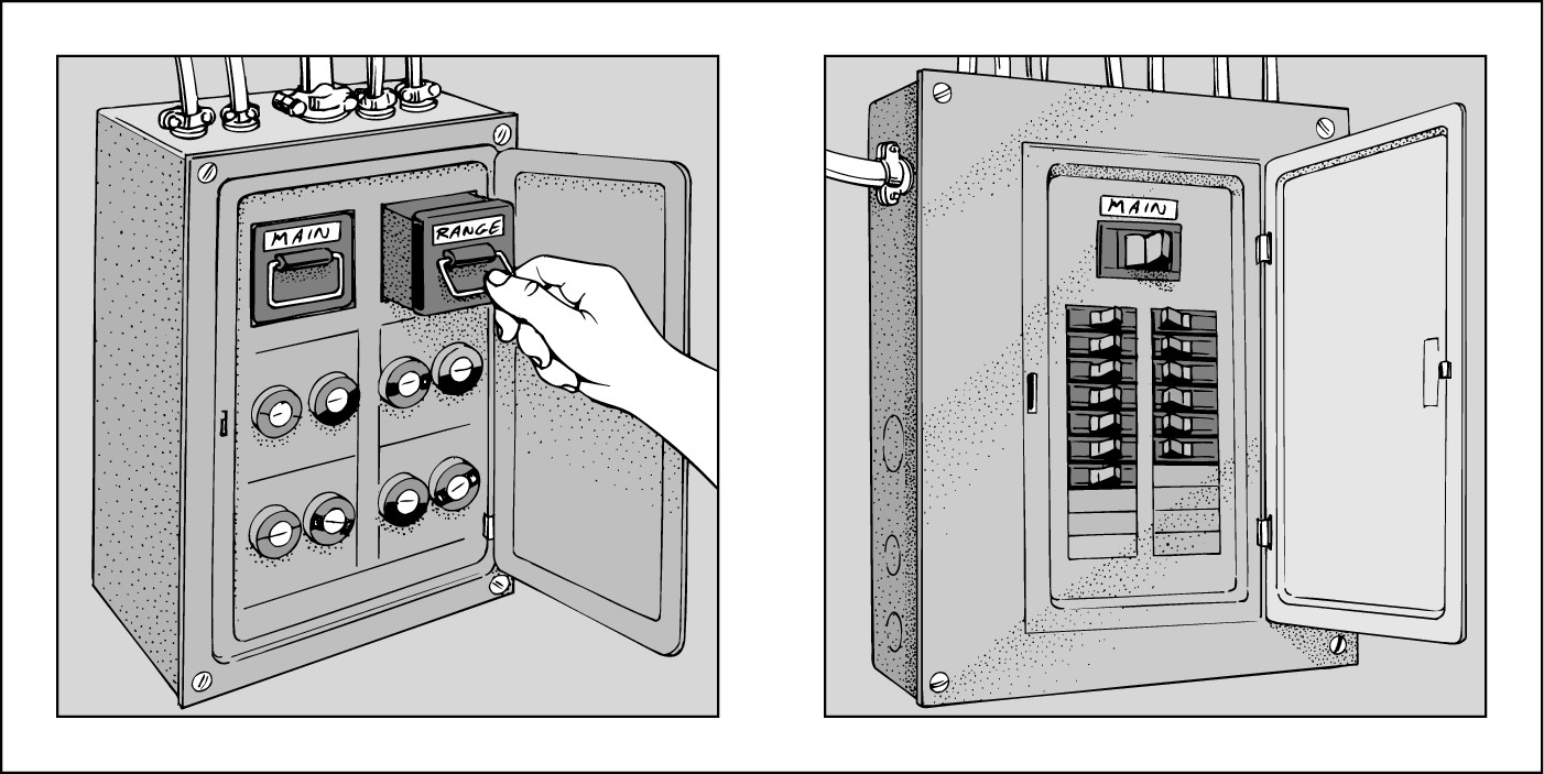
Each circuit is protected by either a fuse or a circuit breaker, both of which you can see in Figure 8-1. If a short circuit occurs anywhere in the wiring, if the wires overheat, or if an appliance malfunctions or catches fire, the fuse or circuit breaker shuts down power to that circuit. Additionally, the entire panel is protected with a master or main fuse or breaker.
|
Figure 8-1: A fuse box panel (left) and a circuit breaker panel (right). |
|
 Fuses: Houses that are more than about 30 years old often have fuses rather than circuit breakers to protect the wire circuits. To shut down a circuit in these homes, you have to remove the fuse. Shut off the power to the electrical panel before replacing fuses. Look for a fuse labeled Master or Main (usually located at the top of the electrical panel); pull this handle and remove the rectangular block containing the main fuses to shut down the power to the entire house. Make sure you have a working flashlight on hand!
If the fuses aren’t labeled, look into the glass window of each fuse to determine which one is blown. A good fuse shows a solid metal bar; a bad one usually has either a broken bar or a discolored glass window. Unscrew the blown fuse and replace it with one of equal amperage. Restore the power by replacing the main fuse.

Have replacement fuses on hand at all times.
 Circuit breakers: Newer homes have circuit breakers — protective switches that enable you to fix short circuits without turning off the power. Circuit breakers simply switch off when they become overloaded, but the breaker doesn’t flip fully to the Off position. To reset a circuit breaker, flip it fully to the Off position and then fully in the opposite direction, to the On position. If the breaker shuts off again, you have a short or some other problem that needs to be fixed before you attempt to switch it on again.
Working with live wires is never a good idea, and sometimes wires from more than one circuit may be present in a single outlet. So to ensure that the electricity is turned off on every circuit you come in contact with, purchase an inexpensive neon voltage circuit tester. This little device lets you know whether a circuit has power running to it. The tester’s not a loud, dust-spewing, macho tool, but it could save your life.

When it comes to electricity, always be prepared
To prepare for electrical emergencies, familiarize yourself with the electrical entrance panel — the circuit breaker box usually found in the utility room or basement. Have a flashlight with good batteries somewhere near the electrical panel to give you good light for looking inside the panel — remember, the overhead light may not be working when you need to change a fuse.
The electrician who wired your house should have marked each circuit on the panel with a label telling which lights or appliances it controls. But things don’t always happen the way they should, and you may find yourself with a panel of unlabeled breakers. Before a short circuit leaves you in the dark trying to guess which fuse or breaker controls what, get down to business and label those breakers yourself.
To label the breakers, plug a lamp into each receptacle and turn on all the lights in your house. Then go to your electrical panel and turn off each circuit breaker, one at a time. Have a helper call out which lights or appliances shut down and are, therefore, on that circuit. Label all the breakers with lists of what they control.
Labeling the circuits can be a one-person job. Plug a radio into the outlet you’re testing and turn up the volume so that you can hear it from the electrical panel. When the radio stops playing, you know that you’ve found the circuit that connects to that fuse or circuit breaker.
Wiring Switches and Receptacles
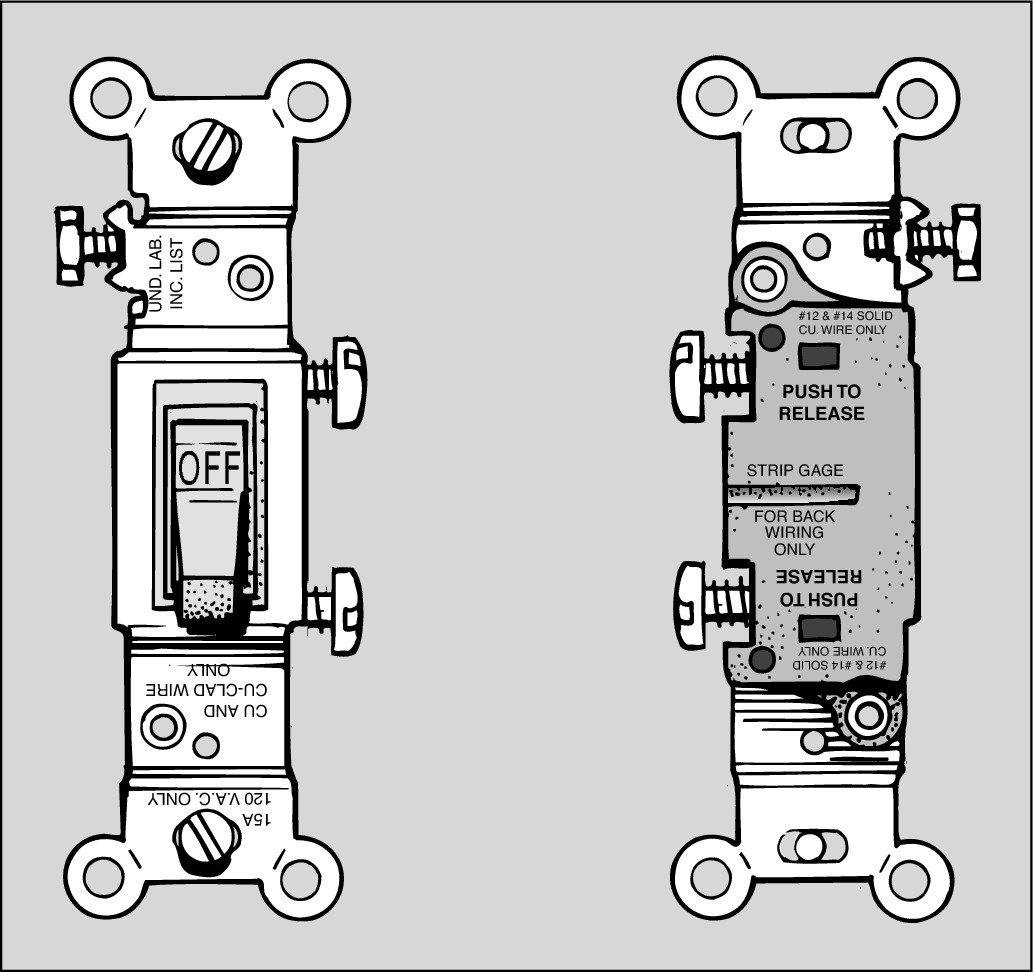
If a switch fails to function or a receptacle (commonly called an outlet) no longer holds a plug securely, it should be replaced, but often people just want to upgrade, change style, or modify the configuration of outlets to meet changing styles or needs. Most modern switches and receptacles have screw terminals on each side and may also have holes in the back to accept the end of the wire, as shown in Figure 8-2. Although plug-in connections may be more convenient, they are less reliable than those at screw terminals, so don’t use them!
|
Figure 8-2: Single-pole switches have two screw terminals on the side and a possible third green terminal for the ground wire. The backside of the switch has holes for back-wiring the device. |
|
You can easily loosen the screws on the side of the device with a standard screwdriver (turning counterclockwise), but you may find getting the wires out of the back of the device tricky. To remove these wires, insert the blade of a small screwdriver into the slot under the hole into which the wire is inserted and push in as you pull the wire loose. Pushing the blade of the screwdriver into the slot releases the grip on the inserted wire. Here are descriptions of the wires and where they go:
 The white (neutral) wire connects to the silver screw, or you place it in the back wire hole on the same side of the device as the silver screw.
 The black (hot) wire goes to the brass screw or into the hole in the back of the device on the same side as the brass screw. This wire is sometimes red.
 The green or bare copper (ground) wire, if the device has one, attaches to the green screw terminal on the switch or to the electrical box.

Making a wire-to-wire splice
You sometimes find that the existing wires are very short and difficult to work with. You can make the job easier by splicing on an additional length of wire.
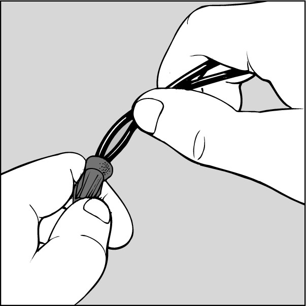
You may also have to join the ground wire of an appliance (ground wires are usually bare copper or green) with other ground wires in the electrical box. You can do that most easily with a twist-on wire connector called a wire nut. Strip off about 1 inch of insulation from the end of the wires and use pliers to twist their bare ends together with electrician’s pliers. Then screw the wire nut down over the twisted wires until it’s tight.
Wire nuts come in many sizes, and using the proper size is important. If the nut is too small, you can’t screw it down over the wires and provide an insulated shield. If the nut’s too large, it screws down over the wires but may shake loose. Look on the wire nut package for the number of wires of a given size that this wire nut can join. For example, a wire nut could join four #14 wires but only three #12 wires. (The number refers to the gauge of the wire — the smaller the number, the thicker the wire.)
Swapping a light switch
Most kitchen and bedroom switches are the single-pole type and are designed to control a light or receptacle from a single location. Hallways, on the other hand, usually have three-way switches that are designed to control a light or receptacle from two locations. Sometimes, an electrician places a four-way switch between three-way switches to allow control of lights or receptacles from three separate locations.
.jpg)
Replacing a single-pole switch
If the switch has On and Off embossed on its body and it’s the only switch that controls lights or receptacles, it’s a single-pole switch. To replace this kind of switch, follow these steps:
1. Turn off the power to the switch at the main circuit breaker or fuse panel.
2. Unscrew and remove the switch plate; then use a voltage tester to make sure that the circuit is dead.
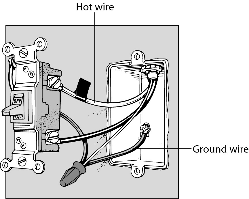
3. Unscrew the switch from the electrical box and pull it out with the wires still attached, as shown in Figure 8-3.
Two or three wires will be attached to the switch: an incoming hot wire, which is black, and a return wire, which carries the load to the fixture. It may be black, red, or any other color except green, and sometimes a grounding wire, which is green or bare copper. There may be other wires in the box, but you are only dealing with the ones connected directly to the switch.
.jpg)
You may find a white wire that has black tape on it connected to the switch, as in Figure 8-3. This tape indicates that the white wire is being used as a black or colored wire in the switch leg, so it’s not neutral.
|
Figure 8-3: Both wires leading to a single-pole switch are hot. If wired with two conductor cables, the white wire is marked with black tape. |
|
4. Compare your new switch with the one you’re replacing to find the corresponding locations for the electrical screw connectors.
Because the power is off, you can match up the connectors the easy way: Instead of disconnecting all the wires at once and possibly getting confused, unscrew and connect one wire at a time.
5. Attach the first wire you unscrew to the same-colored screw on the new switch as it was on the old; do the same with the second.
To connect a wire to a terminal, strip off about 1/2 inch of insulation, using a wire stripper, and twist the end into a clockwise loop with long-nose pliers. The loop must wrap at least two-thirds but no more than three-quarters of the way around the terminal screw. Hook the wire clockwise around the screw so when you tighten the screw with a screwdriver, the clockwise force of the tightening screw makes the loop wrap tighter around the screw.
6. Gently push the new, wired switch back into the electrical box and screw it in place.
7. Screw on the switch plate and turn on the power.
Replacing a three-way switch
A three-way switch is a handy convenience to control a light from two locations, such as at the top and bottom of a staircase. If the words On and Off aren’t embossed on the switch and it’s one of two switches that control a single light or receptacle, you have a three-way switch. Seems like it should be called a two-way switch, right? The name refers to the fact that these switches have three terminal screws.
To replace a three-way switch, follow these steps:
1. Turn off the power to the switch at the circuit or fuse panel.
2. Unscrew and remove the switch plate; then use a voltage tester to make sure that the circuit is dead.
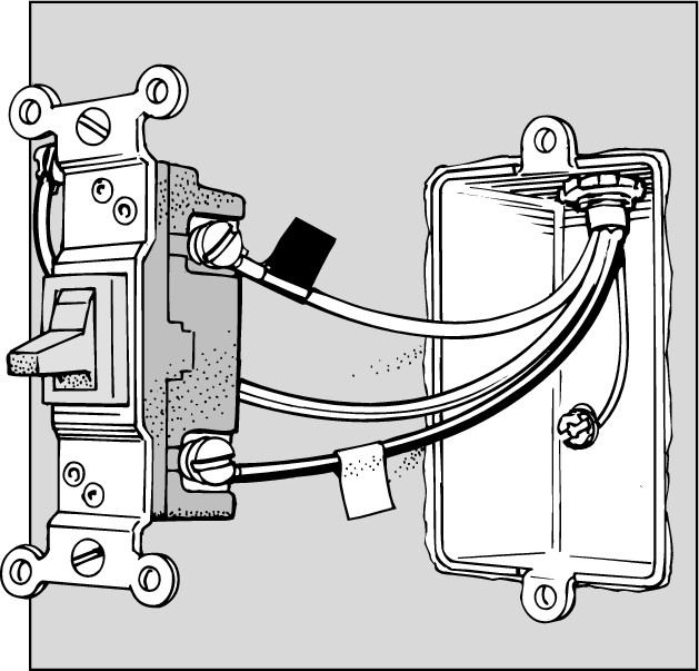
3. Unscrew the switch from the electrical box and pull it out with the wires still attached, as shown in Figure 8-4.
A three-way switch has at least three wires and possibly four, depending on whether it has a ground wire. Two wires attach to brass screw terminals, which are usually at the top of the switch, and an additional wire attaches to a dark-colored (not green) screw terminal, which is usually at the bottom of the switch. Mark this third wire with a piece of tape and mark the wire on the same side of the switch directly above it with a piece of different-colored tape.
The new switch may have the electrical screw connectors in slightly different locations than the switch you’re replacing. Most switches have a pair of terminals on opposite sides of the switch top and a single terminal at the bottom.
|
Figure 8-4: A three-way switch controls a light from two locations. The common screw terminal is wired to the light or to the source of power. |
|
4. Remove the wires from the switch.
5. Attach the tagged wires to the corresponding terminals of the new switch.
Alternatively, you may choose to transfer one wire at a time from the old switch to the new switch.
6. If the existing switch has a green ground wire, attach the wire to the green screw terminal on the new switch or to the electrical box.
7. Push the new, wired switch back into the electrical box and screw it in place.
8. Screw on the switch plate and turn on the power.
Replacing a four-way switch
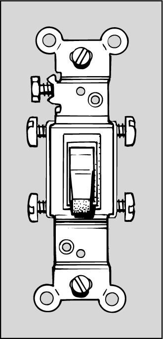
If the switch doesn’t have the words On and Off embossed on its body and it’s the center switch of three switches that control a single light or receptacle, it’s a four-way switch. Figure 8-5 shows a typical four-way switch.
To replace a four-way switch, follow these steps:
1. Turn off the power to the switch at the circuit panel or fuse box.
2. Unscrew and remove the switch plate; then use a voltage tester to make sure that the circuit is dead.
3. Unscrew the switch from the electrical box and pull it out with the wires still attached.
This switch has at least four screw terminals. It may also have a fifth ground terminal (green).
4. Mark the location of the four wires with tape so that you can replace them on the new switch; then remove the wires from the switch.
Alternatively, you may choose to transfer one wire at a time from the old switch to the new switch.
5. Attach the wires to the corresponding terminals of the new switch.
If the existing switch has a green ground wire, attach it to the green terminal on the new switch or to the electrical box.
6. Push the new, wired switch back into the electrical box and screw it in place.
7. Screw on the switch plate and turn on the power.
|
Figure 8-5: A four-way switch has four screw terminals plus an optional grounding screw. |
|
Replacing a standard switch with a dimmer switch
Replacing a standard single-pole or three-way switch with a dimmer switch is no different than replacing a standard switch. Remember: Dimmer switches don’t work on most fluorescent fixtures, and low-voltage lighting requires special low-voltage dimmers.

To replace a standard switch with a dimmer switch, follow these steps:
1. Turn off the power to the switch at the circuit or fuse panel.
2. Unscrew and remove the switch plate; then use a voltage tester to make sure that the circuit is dead.
3. Unscrew the switch from the electrical box and pull it out with the wires still attached.
4. Remove the wires from the old switch.
Dimmer switches are usually connected to the house wiring by short lengths of wire coming out of the switch body rather than by screw terminals.
5. Use the connectors (wire nuts) supplied with the fixture to attach the black wires coming out of the dimmer switch to the colored wires that were attached to the terminals on the old switch, as shown in Figure 8-6.
First, twist the wires together, and then screw on the wire nut.
6. Push the new switch back into the electrical box and screw it in place.
The body of a dimmer is larger than the switch being replaced. Don’t just force it in. Often, you need to reposition or better organize the wires first to make room for it.
7. Screw on the switch plate.
8. Push the control knob, if there is one, onto the shaft protruding from the switch.
9. Turn on the power.
|
Figure 8-6: Some dimmer switches have screw terminals and are wired like a single-pole switch; others have wire pigtails that are spliced with wire nuts. |

|
Replacing duplex receptacles
The procedure for replacing a duplex (two-outlet) wall receptacle is the same as for replacing a switch. The only difference is that, depending on where the receptacle is located in the wiring scheme of your house, it may have more wires attached to it than you find attached to a light switch.
Look closely at the terminal screws of the new duplex receptacle. On each side of the receptacle is a pair of terminal screws. The upper screw is connected to the upper outlet, and the lower screw services the lower outlet. A thin metal break-off tab connects these screws. This tab enables you to attach a single wire to either screw and feed electricity to both outlets of the receptacle. If the tab is broken off, you can connect the upper and lower outlets to separate wires and control them independently.
If the receptacle is wired to the end of a series of receptacles, it usually has only two wires, and possibly a third ground wire. If it isn’t the last receptacle, two additional wires may be connected to it in order to carry current to the next receptacle. Just rewire the new receptacle the same way the old one was wired. (See Figure 8-7.)
|
Figure 8-7: A recep- tacle in the middle of a series (left) and at the end of a series (right). |

|
You may also wire the receptacle so that a switch controls the upper outlet and the lower outlet is on, or hot, all the time. In this case, you need to remove the break-off tab connecting the two sets of like-colored terminals on each side of the receptacle. Otherwise, the tab remains intact, and you can see a metal bridge connecting the terminals.

Replacing a standard receptacle
To replace a standard duplex receptacle, follow these steps:
1. Turn off the power to the receptacle from the main fuse or circuit panel.
2. Unscrew and remove the cover plate; then use a voltage tester to make sure that the circuit is dead.
3. Unscrew the receptacle from the electrical box and pull it out with the wires still attached.
Note where the white and black wires are attached to the old receptacle.
4. Remove the wires.
5. Carefully inspect the old receptacle to see if the break-off tab connecting the two sets of terminals on each side of the receptacle is broken off. If it is, remove the corresponding tabs from the new receptacle.
To break off the tab, grip it with long-nose pliers and bend it back and forth until it breaks off.
6. Attach the wires to the terminals of the new receptacle.
If the wiring has a green ground wire, attach it to the green terminal on the receptacle or to the electrical box.
7. Push the new receptacle back into the electrical box and screw it in place.
8. Screw on the cover plate and then turn on the power.
Replacing a receptacle with a GFCI
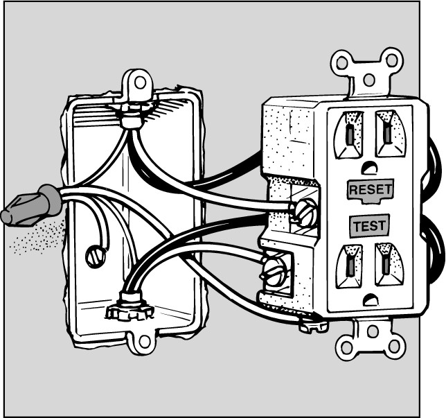
A GFCI (ground fault circuit interrupter ) receptacle is the same as an ordinary receptacle, except that it has a sensitive built-in circuit breaker and reset switch. Building codes require that you install this device in outlets located in areas prone to dampness, such as bathrooms, kitchens, basements, garages, and outdoors.

We’re sure that you don’t have any crash-test dummies in your household foolish enough to volunteer to stick a finger in a receptacle to test the GFCI. Fortunately, these devices have a Test button on them so that you can check that they’re functioning properly instead of finding out the hard way. Press the Test button, and the device trips and shuts everything down. To reset the device, press the Reset button.
You can install a GFCI receptacle the same way you install an ordinary receptacle. To replace a standard duplex receptacle with a GFCI receptacle, follow these steps and refer to Figure 8-8:
1. Turn off the power to the receptacle from the fuse or circuit panel.
2. Unscrew and remove the cover plate; then use a voltage tester to make sure that the circuit is dead.
3. Unscrew the receptacle from the electrical box and pull it out with the wires still attached.
4. Note where the white and black wires are attached to the old receptacle and then remove the wires.
5. Transfer the wires from the old receptacle to the GFCI.
GFCI receptacles are connected to house wiring either by short lengths of wire coming out of the receptacle body or by screw terminals.
If the GFCI receptacle has wires, use the wire connectors (wire nuts) supplied with the fixture to attach the black wires coming out of the GFCI receptacle to the colored wires that were attached to the terminals on the old receptacle. Twist the wires together first and then screw on the wire nut.
If the GFCI receptacle uses screw terminals, attach the colored wires to the terminals of the new receptacle. If wiring includes a green ground wire, attach it to the green terminal on the receptacle or to the electrical box.
6. Push the new receptacle back into the electrical box and screw it in place.
7. Screw on the cover plate and turn on the power.
|
Figure 8-8: A ground fault circuit interrupter (GFCI) is wired like a standard receptacle. |
|
Repairing a Faulty Lamp
As electrical appliances go, lamps are very reliable. But after a while, the socket may act up and cause the lamp to flicker, to be difficult to turn on, or to just flat out refuse to light. If this sudden disobedience gives you the perfect excuse to get the hideous thing out of your living room, do it. But if you aren’t ready to part with the little feller, you can replace the socket and give the lamp a new life. You can replace a socket so easily that, even if it’s not your favorite lamp, you may want to fix it and give it to someone else, like your nosy neighbor.
You can purchase replacement lamp parts at any hardware store or home center. These parts are standard; you can buy lamp cord by the foot, and you can use just about any type of plug to replace the one on your old lamp.
You can find several varieties of lamp socket switches. You control some by pushing a short shaft on the side of the switch, others by turning a knob, and still others with a pull chain. You also need to consider whether your present lamp has a three-way bulb in it. If you could turn the lamp on to several degrees of brightness, be sure to purchase a socket switch that’s designed to control a three-way bulb.

To replace a lamp socket, follow these steps:
1. Unplug the lamp.
2. Remove the shade, bulb, and harp (the wired shape that holds the shade).
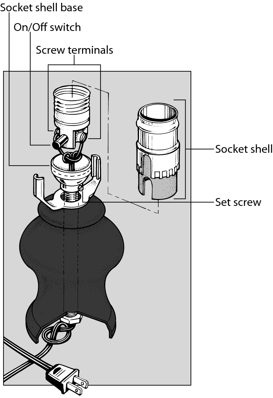
3. Snap off the socket shell from the socket shell cap, as shown in Figure 8-9.
|
Figure 8-9: Removing the socket shell. |
|
Most sockets have the word Press stamped in two places on the shell. Squeeze the shell at those points and pull up to remove it. If the shell doesn’t budge, push the end of a screwdriver between the base of the socket and the side of the shell and then pull the shell up and off the socket base.
4. Pull the socket switch up out of the shell base to expose enough of the switch to reveal the two wires attached to it.
If the screws are loose, tighten them and reassemble the lamp. Loose screws may have been the lamp’s only problem. If the lamp works after you tighten up the screws, great! If not, take it apart again and proceed with the following steps.
5. Unscrew the wires.
A lamp switch has a brass screw to which the hot (black) wire is attached and a silver screw to which the neutral (white) wire is attached. Lamp cords, however, don’t have colored wires in them. So, before you remove the wires from the old switch, note which color screw each wire is connected to.
6. Loosen the socket cap set screw and then unscrew and discard it along with the old socket shell and socket.
7. Screw the wire leads to the new socket.
8. Place the new socket shell over the socket and push the cover down until it snaps into the new socket shell cap.
9. Replace the harp, light bulb, and shade.
Replacing a Ceiling Fixture
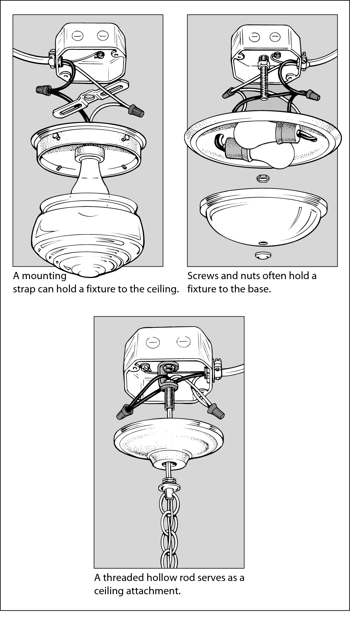
Residential ceiling fixtures come in many different shapes, and people have devised many ways to attach them to the ceiling. (See Figure 8-10.) Most of the time, a central threaded hollow rod holds a chandelier in place. Ceiling fixtures hang by two screws that attach the fixture base to the outlet box or to a mounting strap in the outlet box.
No matter how you suspend a fixture from the ceiling, the wiring is simple. Other wires may pass through the box, but you have to deal with only three wires: a colored wire (usually black), a white wire, and a green ground wire. These three wires are joined together with twist-on wire connectors.

To replace a ceiling fixture, follow these steps:
1. Turn off the power.
.jpg)
You may find several pairs of wires in the ceiling box. Some of these wires may be wired to different circuits than the fixture you’re working on. Be safe: Use a circuit tester or turn off the power to the whole house to ensure that all the wires in the box are dead.
2. Remove the light bulb cover and bulbs from the fixture.
3. Unscrew the screws or nuts holding the fixture base to the ceiling box.
4. Lower the fixture base and remove the electrical tape or wire nuts from the black (hot) wire, white (neutral) wire, and, if present, green (ground) wire.
5. Attach the wires from the new fixture with wire nuts to the corresponding wires in the electrical box.
|
Figure 8-10: Ceiling fixtures stay secure with different mounting hardware. |
|
6. Raise and position the new base plate so that you can screw the new bolts through it to attach it to the mounting strap.
7. Screw in new light bulbs, install the cover, and turn on the power.
Installing a ceiling fan
A ceiling fan is a stylish and functional addition to any room. If the room already has a ceiling outlet, wiring a ceiling fan is the same as wiring any ceiling fixture. If the room doesn’t have an overhead box, hire an electrician to install the box and fish the wires through the walls and across the ceiling. Save the fun of installing the actual fan for yourself.

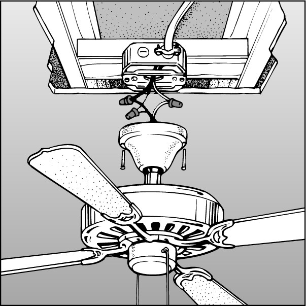
If you can access the ceiling on which you want to attach the fan from the attic or from an overhead area, you have several choices in the type of box you install (see Figure 8-11). If you can’t get to the area above the box, you have to use an adjustable hanger bar designed for installation through the hole left by the existing ceiling box. If you have no idea whether your house has an attic, maybe you shouldn’t be playing with wires.
|
Figure 8-11: Attic access allows options in electrical boxes for attaching your ceiling fan. |
|
To replace a ceiling fixture, follow these steps:
1. Turn off the power at the fuse or circuit panel.
.jpg)
You may find several pairs of wires in the ceiling box. Some may be wired to circuits other than the one that the fixture you’re working on uses. Be safe: Use a circuit tester or turn off the power to the whole house before attempting to install a ceiling fan. That’s the only way to be sure that all wires in the box are dead.
2. Remove any light bulb cover (such as a globe) and bulbs from the fixture.
3. Unscrew the screws or nuts holding the fixture base to the ceiling box.
4. Lower the fixture base and remove the electrical tape or wire nuts from the black (hot), white (neutral), and, if present, green (ground) wires.
5. Disconnect the wires to the existing ceiling box and remove it.
First, loosen the cable clamp screw that secures the incoming cable to the box. Then remove the box, working from above, if possible. Otherwise, remove any accessible fasteners (nails or screws) that attach it to the framing or push it up into the cavity to pry it from the framing or bend its hanger bar, depending on how it is attached.
6. Follow the manufacturer’s directions to install the adjustable hanger bar and ceiling box.
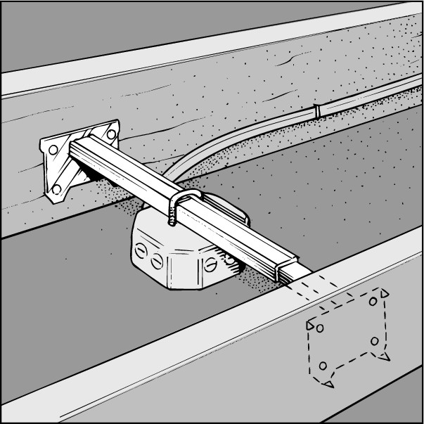
You install most hanger bars by pushing them through the hole in the ceiling left by the old electrical box. When you have the hanger bar completely through the hole, rotate it until it’s perpendicular to the ceiling joists. The bar expands until it engages the ceiling joists. The ends of the hanger bar are equipped with sharp steel pins that dig into the wood joists when the hanger bar is expanded, as shown in Figure 8-12. You then attach the special ceiling box to the hanger bar, locking it in place to provide a secure base for the fan.
|
Figure 8-12: The hanger bar holds the fan firmly within the framing of the ceiling. |
|
7. Assemble the fan according to the manufacturer’s instructions.
A fan kit contains a ceiling hanger bracket designed for that particular model. Follow the directions and bolt the bracket to the ceiling box. The installation kit for the fan should provide all the necessary hardware.
Ceiling fans are heavy, so they require support while you attach the wires. Most models provide a way for you to suspend them below the ceiling box while you attach the wires. If yours doesn’t, get a helper to support the fan assembly while you attach the wires.
Wiring schemes differ slightly from fan to fan, depending on whether they’re equipped with a light or speed control. The basic installation of a ceiling fan is no different from that of a standard light fixture. Use wire nuts to attach the fan’s black or colored wire and white wire to matching wires in the ceiling box. If the wiring has a green ground wire, attach it to the green or bare wire in the box.
8. Complete the attachment of the fan assembly to the ceiling box.
9. Install the trim and fan blades according to the manufacturer’s directions.
10. Turn on the power and test the installation.
Installing track lighting
From its theatrical roots onstage, track lighting has evolved into individual fixtures along a track mounted on a wall or ceiling. Because you can place the light fixtures anywhere on the track and adjust their direction, a track lighting system is a good choice when you want to direct light to a specific area, like a wall of artwork or down a long hallway, or when you want to accommodate changing lighting needs.
An advantage of track lighting is that the track can be powered by a single source, usually a ceiling box. Because track systems vary, become familiar with the assembly before you begin following the instructions to install it.
One end of the track is designed to accept wiring from the ceiling outlet and connect it to the rest of the track. This end is attached to a plate that screws to the ceiling box. The wiring scheme is exactly the same as for any fixture. You connect like-colored wires together, and the green or bare ground wire attaches to the grounding terminal on the track or cover plate.
Follow these basic steps to install a track lighting system in an existing ceiling box:
1. Turn off the power from the fuse or circuit panel.
.jpg)
You may find several pairs of wires in the ceiling box. Some of these wires may be controlled by different circuits than the fixture you’re working on. Be safe: Use a circuit tester or turn off the power to the whole house to be sure that all wires in the box are dead.
2. Remove the old fixture as described earlier in this section.
3. Pull the existing black or colored wire, white wire, and green or bare wire that were connected to the old fixture through the opening in the new cover plate.
4. Attach the plate to the ceiling box with the screws provided.
5. Use the lighting track as a template to locate the position of the mounting screws on the ceiling.
Have a helper hold the track in place while you use a pencil to transfer the location of the mounting holes in the track to the ceiling.
6. Drill a hole for the mounting toggle bolts in the ceiling.
Depending on the weight of the track, manufacturers specify different types of fasteners for holding the track system to the ceiling. Most even supply the fasteners. In some cases, you only need plastic plug-type anchors, but to be on the safe side, we recommend installing toggle bolts. This type of anchor holds the most weight and isn’t difficult to install. It requires a hole in the ceiling the same diameter as the folded toggle.
7. Follow the manufacturer’s instructions for securing the track to the ceiling.
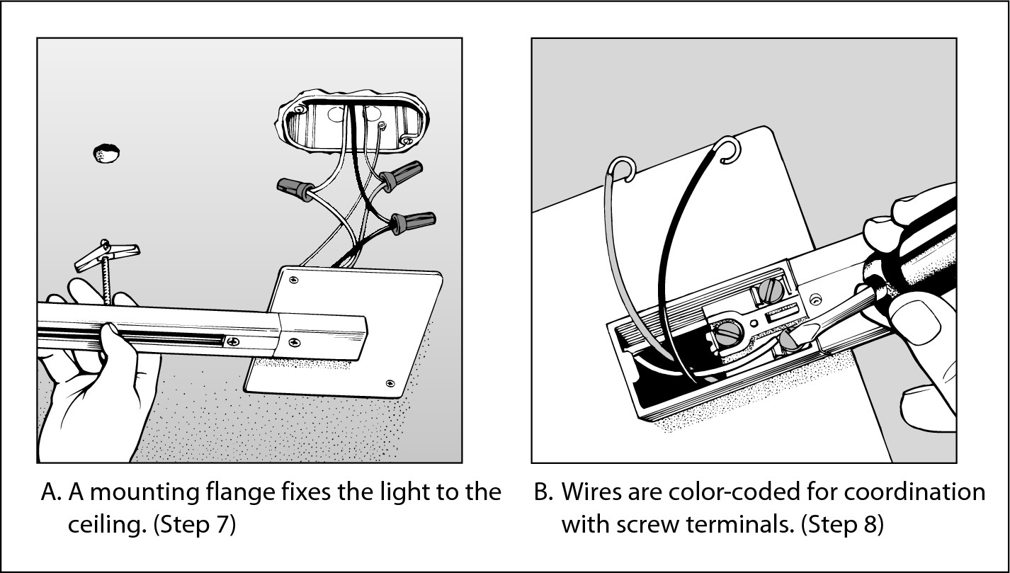
If toggle bolts hold up the track, you have to preassemble them on the track and then hold the whole assembly in place while you push the individual toggles through the predrilled ceiling holes, as shown in Figure 8-13. Thread the screw through the mounting hole in the track and then reinstall the toggle on the screw. After you push the folded toggle through the hole in the ceiling, it unfolds inside the ceiling and provides a secure grip. Tighten the screw to pull the track tight to the ceiling.
8. Pull the wires through the end of the track and attach them to the screw terminals, as shown in Figure 8-13.
The black or colored wire goes on the brass-colored screw and the white wire on the silver screw. Attach the bare or green grounding wire to the green screw.
9. Install the cover plate on the end of the track to hide the wiring.
10. Follow the manufacturer’s directions for mounting the light fixtures.
You attach most track fixtures by slipping a mounting flange into the center channel of the track and then turning the fixture to force the flange under the track so that it contacts the internal wiring.

|
Figure 8-13: Track lighting can provide focused illumination within your home. |
|
Adding a receptacle or switch by using surface wiring
If you don’t mind the industrial look of surface wiring, the easiest solution may be to add an outlet or switched ceiling fixture. It’s a great solution for wiring on concrete walls, such as in a basement. With surface wiring, you eliminate the hassle of running wires through walls. If you already have an outlet in the room, you can use a surface wiring system to expand it.
A protective system called a raceway contains the wiring like a hard-covered extension cord. Raceway systems vary by manufacturer, but you install all of them in basically the same way.

Here are the basic steps for extending a circuit from an existing wall outlet to an overhead light fixture controlled by a single pole switch:
1. Turn off the power at the fuse or circuit panel.
.jpg)
You may find several pairs of wires in the ceiling or wall box. Some of these wires may be connected to different circuits than the fixture you’re working on. To be safe, use a circuit tester or turn off the power to the whole house so that you can be sure that all the wires in the box are dead.
2. Decide on a source of power.
An existing receptacle is your best choice. Otherwise, you’d have to run a new circuit — clearly a job for an electrician.
3. Sketch out the system.
You need an extension frame to fit over the existing outlet box to start the extension and enough raceway and fittings to connect the outlet to the new ceiling fixture. You also need a surface-mounted ceiling fixture box and a surface-mounted light fixture box. You can find all these components and the wires at most home centers.
4. Work from the ceiling fixture back to the outlet and install the fixture to the ceiling with the hardware provided.
Secure the box base to the ceiling at a joist, or use hollow-wall fasteners.
5. Mount the light switchbox in a convenient location on the wall.
6. Install the raceway between the ceiling fixture and the switchbox.
The raceway channels that hold the wires running from box to box attach to the walls with special hardware supplied by the manufacturer. Some styles use plastic wall anchors, and some use toggle bolts, but all are easy to install. These systems provide junction fittings for rounding corners, T-fittings for joining two raceways, and connectors for joining the raceways to the switchbox (see Figure 8-14).
7. Install the raceway between the switchbox and the outlet.
8. Run the wires in the raceway.
To wire the fixture, you need a black wire, a white wire, and a green ground wire. Feed these wires into the raceway between the wall outlet and the switchbox. Leave a loop a foot or so long at each end so that you can wire up the switch and fixture. Similarly, run the wires from the switch to the ceiling fixture, as shown in Figure 8-14.
9. After the wires are in place inside the raceway, snap on the cover and junction fittings.
10. Install the ceiling fixture while there’s no power in the circuit.
Electrical power doesn’t flow to the ceiling fixture until after you connect it to the wall receptacle, so now is the safest time to install the light fixture or new receptacle.
11. Install the single-pole switch.
Refer to the section “Replacing a single-pole switch,” earlier in this chapter, for instructions on replacing a switch. Basically, you have three wires running through the wall switchbox to the ceiling box. Tuck the white wire into the back of the box. Cut the black wire in the middle of the loop you made when you installed the wires in Step 8. Strip off about 1 inch of insulation from the end of these wires and then attach the black wires to the screw terminals on the side of the switch.
12. If the switch has a green screw terminal, attach the ground wire to the switch.
Cut the green ground wire and strip off the insulation from each end. Then take a 6-inch piece of green wire and strip off the insulation from each end. Twist one end of the pigtail together with the other two ground wires. Complete the splice by twisting a wire nut onto this bundle. Attach the other end of the pigtail to the green screw on the switch. Then push the switch into the box, secure it with the mounting screws, and install the switch plate.
13. Check that the electrical power is off at the existing wall outlet and then connect the new circuit to the wall receptacle to energize the circuit.
Connect the black wire to the copper-colored screw and the white wire to the silver screw. The green goes to the bare or green wire in the box.
|
Figure 8-14: Ideal for basements and storage rooms, surface wiring is more functional than attractive. |

|
Wiring a Telephone Extension
Adding a phone extension to an existing jack has become embarrassingly easy. You have only four wires to deal with, and they’re all color coded. So as long as you aren’t color blind, installing an extension phone is goof proof. And because phone systems are low-voltage devices, you have little chance of getting shocked.
You can buy everything you need for this project at a home center. Buy a surface-mount modular phone jack and enough round (not flat, modular) four-conductor phone wire to reach from the existing phone jack to the location where you want to install the new wall jack. You can usually buy the wire in 50- and 100-foot spools.
Here are the basic steps involved in wiring a phone extension:
1. Locate the working phone jack most convenient to the new jack you want to install.
Remember that the nearest jack may be in an adjacent room. Running the phone wire from an existing jack to the new location is your biggest challenge, so use your imagination. You can leave the wire exposed because it carries low voltage. You can hide it along the baseboard, tuck it between the baseboard and carpet, or fish it through walls — it’ll be your secret.
2. Decide where you want the new jack to be and mount the base on the wall or baseboard with the hardware provided.
3. Strip 6 inches of the outer insulation off the round telephone wire to expose the red, green, yellow, and black wires inside.
4. Strip 1 inch of the colored insulation off each exposed wire.
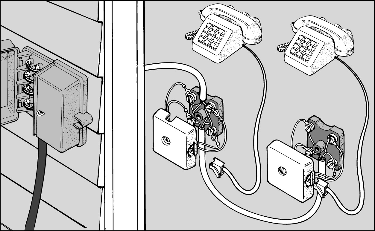
5. Loosen the terminal screws on the new wall jack and wrap the wires clockwise around the matching colored terminals, as shown in Figure 8-15.
|
Figure 8-15: Make a telephone extension connection by matching wire colors with terminals and then wrapping the wires clockwise around the screw. |
|
6. Tighten the screw terminals, making sure that the bare ends of the wires do not touch.
7. Replace the cover of the new wall jack.
8. Strip the insulation off the end of the phone wire at the existing wall jack.
9. Remove the cover from the existing wall jack that you’re tapping into.
10. Loosen the screw terminals and wind each wire around the terminal of the same color.
11. Tighten the screws and replace the existing wall jack cover.
12. Plug the phone line back into the existing jack and test for a dial tone; then take a phone to the new jack and test for a dial tone.
If you hear a dial tone, sign up for a job at the phone company. If not, keep your day job and recheck your wiring.
Replacing a Porch Light with a Security Light
Outdoor security lights use infrared or microwave sensors to light up whenever someone or something passes within a certain range. Use them to safeguard your house without the expense and inconvenience of leaving a harsh light glaring all night. You wire a security light just like an indoor ceiling or wall fixture. To replace an outdoor light fixture with a security light, follow these steps:
1. Turn off the power at the fuse or circuit panel.
.jpg)
You may find several pairs of wires in the wall box. Some of these wires may be wired to different circuits than the fixture you’re working on. Be safe: Use a circuit tester or turn off the power to the whole house to ensure that all the wires in the box are dead.
2. Remove the light bulb cover and bulb from the fixture.
3. Unscrew the screws or nuts holding the fixture base to the wall box.
4. Lower the fixture base and remove the electrical tape or wire nuts from the black (hot), white (neutral), and, if present, green (ground) wires.
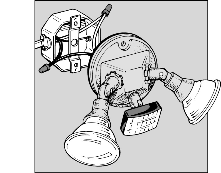
5. Use wire nuts to attach the wires from the new fixture to the corresponding wires in the electrical box, as shown in Figure 8-16.
|
Figure 8-16: Wire nuts attach your new fixture to the like-colored wires in the electrical box. |
|
6. Raise and position the new base plate so that you can screw the new bolts through it to attach to the mounting strap.
An outdoor fixture has a weather gasket that’s inserted between the utility box and the cover plate of the fixture. The gasket helps prevent water from getting into the box. Use the gasket, even if you install the light in a weather-protected outdoor area.
7. Screw in the bulb and replace the bulb cover (if any).
8. Turn on the power and try out your toy.
Most units have a sensitivity adjustment. You may have to do a bit of experimenting with this setting to prevent the light from turning on when a bird flies by or the neighbor’s cat strolls into your yard at 3 a.m. Have a helper walk into the sensor’s field of view. If the unit doesn’t light up, increase the sensitivity until it does.
Adding a Low-Voltage Outdoor Light
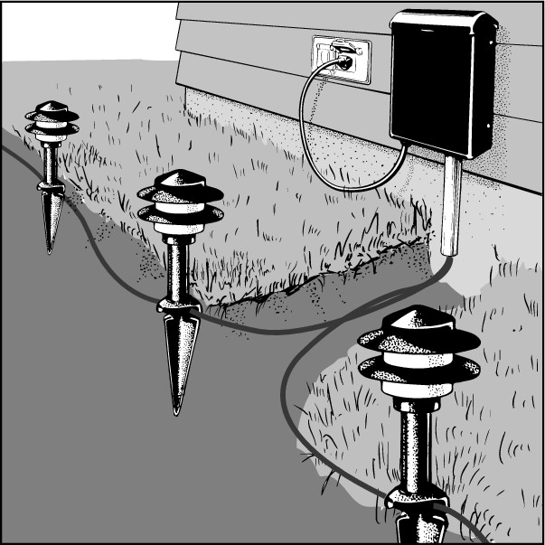
Low-voltage lighting is an ideal choice for outdoor illumination because it’s safe to work with and easy to install. Low-voltage systems, like the one shown in Figure 8-17, are engineered to be modular with easy-to-assemble components. Most systems are powered by a 24-volt transformer attached to a single multiconductor cable, onto which you clamp light modules.
The wiring comes easy. The most time-consuming part is positioning and running the lines, especially if you’re digging up the ground to bury the lines and then covering them again. You can also lay the cable directly on the ground and cover it with mulch. If there’s any chance that the cable can come in contact with your lawnmower or other garden tools, bury the cable by at least 12 inches.
|
Figure 8-17: Low-voltage outdoor lighting comes in modular systems that you can customize to features of your yard. |
|
Here are the basic steps to installing a low-voltage lighting system:
1. Install the transformer close to a grounded outlet.
You should mount the transformer, which converts standard 120-line voltage to 24-volt current, close to an exterior outlet. You can mount a transformer that has a timer inside, but you have to install one with a photoelectric sensor outside so that the sensor is exposed to daylight. For obvious reasons, light-sensitive sensors don’t work in the shade.
2. Lay the cable on the ground according to your plan.
3. Attach the lighting modules to the cable.
Different systems have different connecting schemes, but the general procedure is to position the cable in a slot in the base of the light and then close the clamping mechanism that pierces the low-voltage wire to draw power.
.jpg)
Extract your finger before closing the clamp!
4. When you have all the lights in place, plug the wall-mounted transformer into the exterior outlet and test the lights.
You need to make all permanently plugged-in connections to an exterior outlet weather protected. You can find special outlet covers for this purpose at your local home improvement center.
5. Conceal the cable with mulch or bury it in a shallow trench.
.jpg)