1 Introduction and Background
The Internet of Things (IoT) typically consists a wide-range of Internet-connected smart nodes that sense, store, transfer and process heterogenous collected data [1, 2]. IoT devices are influencing various aspects of life ranging from health [3] and agriculture [4] to energy management [5] and military domains [6]. Its pervasiveness, usefulness and significance have made IoT an appealing target for cyber-criminals [7].
Millions of smart nodes are communicating sensitive and private data through the IoT networks that necessitate protecting IoT against malicious attacks [8]. Above and beyond traditional malware, crypto-ransomware attacks are becoming a challenge for securing IoT infrastructure [9, 10]. IoT-based Botnets (Botnet of Things) and DDoS attacks using an IoT infrastructure are becoming major cyber threat [11, 12]. Therefore, it is important to propose efficient and accurate methods for forensics investigation of IoT networks [13, 14]. Digital cameras are inseparable and substantial subset of IoT nodes that play key role in a wide-range of applications and should possess forensic mechanism to boost its safety and admissibility [15].
Nowadays digital imaging instruments are expanding rapidly and replacing their analog counterparts. Digital images are penetrating all aspects of our life ranging from photography and pharmaceutical pictures to court evidences and the military services [16, 17]. In many applications, validity of images and identification of origin camera are crucial to judge about the images as an evidence. Particularly, electronic image identification techniques are vital in many judiciary processes. For instance, recognizing the source tools could disclose the mystery of felonies. Furthermore, recognizing the source of image is beneficial to every digital forensic approach related to images and videos [18].
To identify source camera of a taken image, it is necessary to have knowledge about what processing actions are performed on the real scene and how it has influenced final digital outcome. Majority of identification techniques have been proposed in this regard. A sizeable proportion of these methods leverage sensor pattern noise because it remains in image as a fingerprint of digital imaging sensor which is highly connected with the type of camera [19–22]. Lukas et al. [19] proposed a method which identified type of camera using noise correlation relating to Photo Response Non Uniformity (PRNU). In their method, it was important to collect a large-scale dataset of images relating to specified images for averaging them among the residual noise and obtaining Sensor Pattern Noise (SPN). Moreover, they analysed error rates change using JPEG compression and gamma correction.
Li [23] opined that stronger signal component in an SPN is the less trustworthy component and attenuated it. Then, by assigning weighting factors inversely to the magnitude of the SPN components identified the source of images. Kang et al. [24] examined and compared source camera identification performance and introduced camera reference phase SPN and removed image’s contamination and therefore reached more precise classification. They also presented by theoretical and practical experiments that their proposed method could achieve higher ROC outcome compared with [19].
Quiring and Kirchner [25] studied sensor noise in an adversarial environment and focused on sensor fingerprint that is fragile to lossy JPEG compression and proposed a method to accurately detect manipulated images by attackers. Applying camera identification on user authorization process, Valsesia et al. [26] leveraged high-frequency components of the photo-response nonuniformity and extracted it from raw images. They also presented an innovative scheme for efficient transmission and server-side verification. Sameer et al. [27] introduced a two-level classification mechanism using Convolutional Neural Networks to detect authentic and counter-forensic images and then type of undergone attack.
The reminder of this paper is as follows. Section 2 reviews the structure of digital camera and Sect. 3 explains the proposed method and Sect. 4 evaluates the performance of it. Section 5 completes this paper by discussing and concluding about the achievements of this paper.
2 Digital Camera

Stages of imaging in digital camera [22]
Light enters a set of lenses from the scene and is passed through anti-visual filters. Then, it is accessible to color filter array and in each pixel, one of the components of Red (R), Green (G) and Blue (B) is taken into account because this sensor is only able to pass one color in each pixel. Over here, an interpolation process is applied to estimate intensity of two other colors for each pixel using neighborhoods. In the next stage, the sequence of image processing operations like color correction, white color balance, gamma correction, image improvement, JPEG compaction etc., have been performed. Afterwards, the image is saved as a particular image file. Some specifications in this process can be applied for camera type identification such as sensor pattern noise (SPN), camera dependency response function, resampling, color filter array interpolation, JPEG compression and lens aberrations. In this study, we utilize a combination of camera pattern noise and color filter array for recognizing source camera of an image.
2.1 Camera Noise
The noise which is available in images originates from different sources. In order to source camera identification, we explore all types of noise which are caused by camera and has the minor dependency to surrounding environment or the subjects which are imaged.
Based on source of noise, they are categorized as temporal, spatial and a combination of both. The noise which appears in the reconstructed image and is fixed in a definite location of image, indicates Fixed Pattern Noise (FPN). Basically, since it has been fixed from spatial point of view, it can be removed in dark points using signal processing methods. The principle component of FPN is current non-uniformity of the dark points in a charge-coupled device (CCD) sensor. This can be due to photo contact time or high temperature. Complementary metal-oxide semiconductor (CMOS) is the main sources of FPN current non-uniformity of dark points [28]. The considerable point in FPN is that spatial pattern of these changes remains fixed. Since FPN is added to all frames or images produced with a sensor and is independent of light, it can be deleted from the image by reducing a dark frame. The source which is similar to FPN in terms of characteristics is PRNU. In fact, this is the same difference in response to light in pixel when light enters the sensor. One of the reasons is non-uniformity of size of the active areas which throughout light photons are absorbed. PRNU is the result of silicon material heterogeneity and some other effects which have been created during production process.
2.2 Color Filter Array and Bayer Pattern

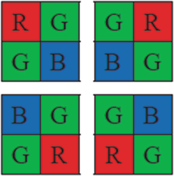
Bayer pattern
It is obvious that the signal which is located in CFA is more powerful and since it is directly received from the sensor is an appropriate option to be used for extraction of features and type detection of digital camera. Therefore, this pattern can be applied as a fingerprint to identify source of image. In fact, it can be recognized that the sampled image in each pixel has been entered directly from sensor of camera or has been interpolated.
3 Proposed Method
Considering the fact that different cameras possess various noise characteristics due to their sensor specifications, disparate patterns should be obtained from the images. To recognize images’ source, the proposed method includes two main building block namely Feature Extraction and PRNU Pattern Classification.
3.1 Feature Extraction

3.1.1 Basic PRNU
- 1.
Extracting pattern noise across the entire image using Eq. (1).
- 2.
Using PCA for dimensionally reduction and eliminating useless components of noise
3.1.2 PRNU Extraction Considering Color Channels
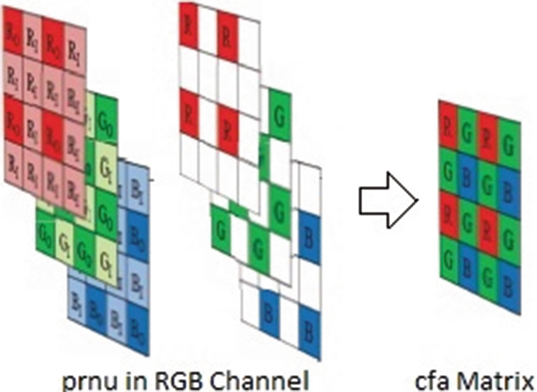
In order to reduce color interpolation error and promote pattern noise, in [22] colors analysis in pattern noise and extraction of Color-Decoupled Photo Response Non-Uniformity are used. For this purpose, it has analyzed image into four sub-images for each color channel and extracted PRNU pattern noise using Eq. (1). To compare the proposed algorithm with this algorithm, we use CD-PRNU instead of extracting PRNU in the first stage of feature extraction. The proposed algorithm considers all color channels in extraction of pattern noise as well as CD-PRNU extraction algorithm. It is notable that CFA pattern has not been certainly recognized in CD-PRNU extraction algorithm and the extracted pattern noise is a combination of pattern noise of all three RGB color channels. Instead, CFA pattern is identified in the proposed algorithm using Choi et al. method [31]. In this regard, we only select the pixels from pattern noise which are related to CFA.
A method for identifying color filer array (CFA) which uses Intermediate Value Counting is presented in [31] and has been formed based on the primary hypothesis that CFA interpolation fills empty pixels using neighbor pixels. As described in Sect. 2.2, there are different pixel patterns for coloring green, red and blue channels. For each channel, a special neighborhood is defined and intermediate value is counted. CFA pattern is estimated by information of these intermediate values in three channels. Finally, one of the four Bayer patterns (RGGB, GRBG, BGGR and GBRG) is attributed to any camera.


Obtaining CFA matrix from PRNU
3.1.3 Reduction of Image Dimensions Using Wavelet Transform

Wavelet transforms bands in a hypothetical image

Wavelet transform bands to level 2
3.2 Noise Classification
Support Vector Machines (SVM) [33] are a set of classification methods relating to supervised learning which analyze data and identify the patterns. To utilize SVM, it is necessary that each of the samples be represented as a vector of real numbers. In our experiments, input part is a vector of features which is extracted from PRNU noise, CFA pattern and its wavelet transform. Furthermore, PCA is applied to reducing dimensions of data and selecting more beneficial elements of data [34]. Output of SVM classifier is a label predicting camera type.
4 Experiments
4.1 Dataset and Settings
Images dataset information
Label | Camera model | Sensor | CFA pattern | Image size |
|---|---|---|---|---|
C1 | Canon EOs400D | CMOS | RGGB | 3888*2592 |
C2 | Kodak EasyShare CX7530 | CCD | GBRG | 2560*1920 |
C3 | HP PhotoSmart E327 | CCD | RGGB | 2560*1920 |
C4 | Panasonic DMC-FZ20 | CCD | RGGB | 3648*2738 |
C5 | Canon PowerShot A400 | CCD | GBRG | 1536*2048 |
C6 | Panasonic Lumix DMC-FS5 | CCD | GRBG | 3648*2736 |
4.2 Results


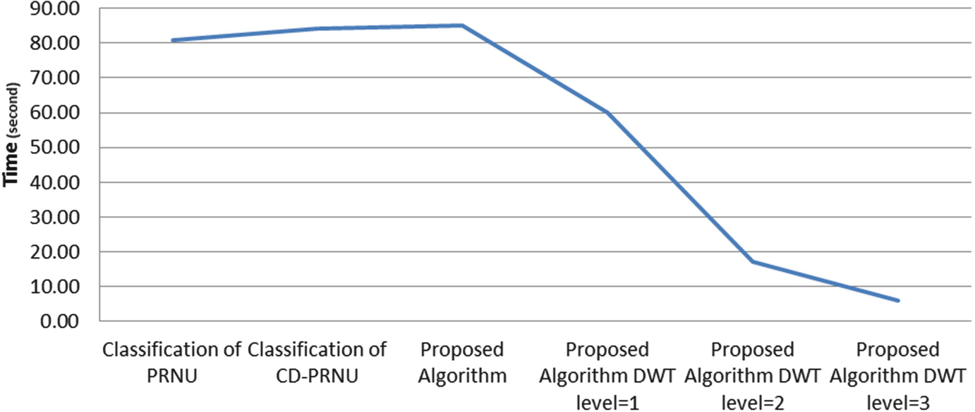
Algorithm comparison in terms of time
Accuracy obtained from the proposed algorithm and comparison with previous methods
PRNU [19] | CD-PRNU [22] | Proposed method | |
|---|---|---|---|
C1 | 91% | 89.00% | 99.50% |
C2 | 83.00% | 83.33% | 91.83% |
C3 | 84% | 90.00% | 97.17% |
C4 | 91.83% | 94.67% | 100% |
C5 | 90% | 86.83% | 99.50% |
C6 | 94.67% | 91.67% | 99.83% |
Average | 89% | 89.25% | 97.97% |
Results of wavelet transform application and image dimensions reduction
l = 1 | l = 2 | l = 3 | |
|---|---|---|---|
C1 | 99.33% | 100% | 100% |
C2 | 85.83% | 84.17% | 83.50% |
C3 | 86.67% | 83.67% | 83.17% |
C4 | 97% | 89% | 82.83% |
C5 | 98.17% | 84.50% | 84.83% |
C6 | 99.17% | 100% | 100% |
5 Conclusion
Nowadays, the Internet of Things penetrating all aspect of our life and enormous digital images are taken in small intervals by IoT nodes for different applications. This soar in usage and importance of IoT necessitates proposing applicable method for forensic issues. Camera identification refers to a category of methods that endeavour to recognize source camera based on images taken by it.
In this paper, an algorithm has been proposed for extracting features so as to digital camera identification. The proposed algorithm has been evaluated by a dataset including images taken by six different digital cameras. To increase accuracy, we proposed a new feature extraction method to generate CFA pattern. Furthermore, to select the principle components of pattern noise and to reduce dimensions of pattern noise, we leveraged HH part of wavelet transform and results demonstrate upsurge of runtime speed. The proposed method outperform 97.07% of accuracy which are higher than the average result obtained in the rival methods, 89% and 89.25% from PRNU [19] and CD-PRNU [22] respectively. To outdo other methods in terms of runtime, we contributed that speed considerably will increases using HH component of wavelet transform while average accuracy remains approximately above 90%.