The CIA triad of confidentiality, integrity, and availability should always be of top importance for the developer. Regarding “integrity,” secure boot is a valuable feature to help maintain integrity claims of a platform. It is also called verified boot. When secure boot is enabled, one component will verify the next component before it executes it. If the verification fails, the next component will not be executed. It seems very useful. But how does the other software know if the secure boot is enabled and enabled correctly? How does the other software know if the secure boot was not disabled by mistake?
Today, even if we believe a system is secure, we still want to let other entities have a way to confirm such secure attributes. Once the system has a way to prove it possesses such attributes, we can say it is trusted.NOTE The definition for “trust” is different from “secure.” From the Trusted Computing Group (TCG) definition, an entity can be trusted if it always behaves in the expected manner for the intended purpose. A trusted system might not be a secure system. For example, if we know a system is infected by a virus and the virus scans the C disk at 5 PM every day and uploads the all doc files to a specific URL via http protocol, we can say this system is trusted and it is not secure.
TCG defines a way to let other software check if the system has booted into a trusted environment. The process is called TCG trusted boot.
Static Root-of-Trust for Measurement (SRTM)
Root-of-Trust for measurement (RTM): The RTM does the initial measurement process. The RTM is some code on the host side. In the real implementation, we have two different types of RTM – static RTM (SRTM) or dynamic RTM (DRTM). We will discuss them later. The RTM may include many components. In those components, the Core-RTM (CRTM) means the component to run the first code after platform reset.
Root-of-Trust for reporting (RTR): The RTR reports the measured information via a TPM PCR and provides the capability to attest to the authenticity of the PCR based upon the TPM identities.
Root-of-Trust for storage (RTS): The RTS provides a protected storage area for keys and data.
Trusted Platform Module (TPM)
A TPM includes all of the trusted capabilities except the root-of-trust for measurement. This book focuses on how to use TPM in the firmware. Refer to the TPM specification or books listed in the references for the detailed introduction to TPM hardware and its capabilities.
The TPM’s Platform Configuration Registers (PCRs) hold the value of the final measurement. The measurement follows the equation given here. This operation is PCR extend:
PCR (new) = HASH (PCR(old) || HASH(Data))
PCR extend is the only way to modify the PCR value. If a platform extends a PCR multiple times, all data is hashed into the PCR.

Firmware Measurement with SRTM
SRTM PCR Measurement
PCR Index | Usage |
|---|---|
0 | SRTM, BIOS, Host Platform Extensions, embedded option ROMs, and PI Drivers |
1 | Host Platform Configuration |
2 | UEFI driver and application code |
3 | UEFI driver and application configuration and data |
4 | UEFI Boot Manager Code (or Initial Program Loader (IPL) in legacy Master Boot Record (MBR)) and Boot Attempts |
5 | Boot Manager Code Configuration and Data (for use by the Boot Manager Code) and GUID Partition Table (GPT) (or legacy MBR Partition Table) |
6 | Host Platform Manufacturer Specific |
7 | Secure boot policy |

Secure Boot and Trusted Boot Flow

Secure Boot vs. Trusted Boot
TPM Device Type
The first TPM production followed TPM specification version 1.2, also known as TPM1.2. However, overtime it became clear that the TPM1.2 specification had some limitations. For example, TPM1.2 only supports the SHA1 hash algorithm and the RSA asymmetric algorithms. Once the ownership of TPM1.2 is taken by OS, the platform BIOS may not use the TPM.
In order to resolve those limitations, TCG defines the TPM specification family 2.0, also known as TPM2.0. TPM2.0 supports cryptography agile. A TPM2.0 device may support SHA1, SHA256, SM3_256, or future algorithms such as SHA3_256 or SHA3_384. TPM2.0 defines a dedicated platform hierarchy for the platform firmware usage. The OS manages storage hierarchy which is independent from the platform hierarchy. TPM2.0 provides a uniform framework for using authorization capabilities and expands the authorization method – clear text password and hash-based message authentication code (HMAC).
Besides TPM1.2 and TPM2.0, the Chinese government defines Trusted Cryptography Module (TCM). TCM provides the root-of-trust for report (RTR) and the root-of-trust for storage (RTS) and supports the trusted boot. It is similar to TPM from the functionality perspective. For example, TCM defines the Platform Configuration Register (PCR), non-volatile memory, endorsement key, identity key, and so on. TCM only supports Chinese cryptography – SM2, SM3, and SMS4.
Similar to TPM, the Trusted Cryptography Module (TCM) is also a passive device. In order to support active measurement, the Chinese government standard defines the Trusted Platform Control Module (TPCM). In addition to RTR and RTS, the TPCM provides the root-of-trust for measurement (RTM). After the system powers on, the TPCM measures the platform BIOS and records the result to PCRs; then TPCM transfers control to the host CPU.
Measurement Report
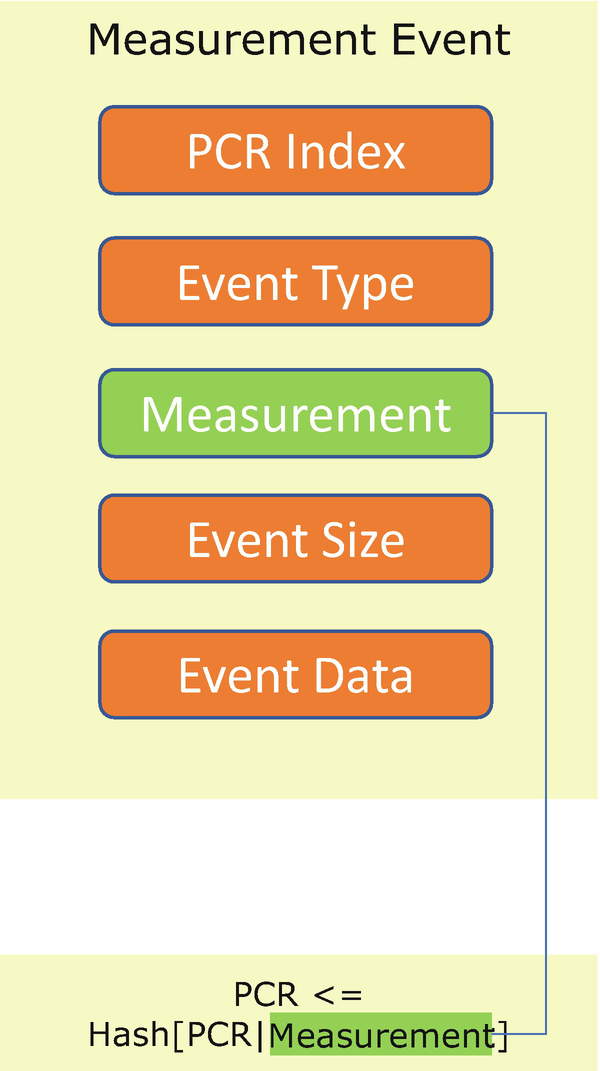
TCG Measurement Event and PCR
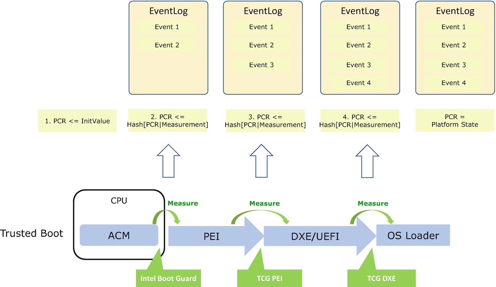
TCG Measurement Event Log Recording During Boot
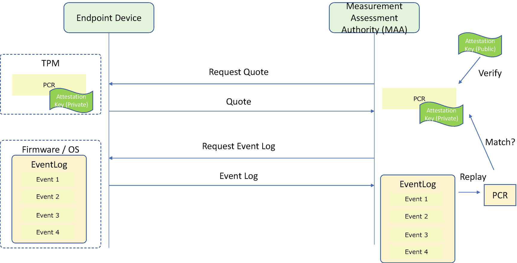
Care must be taken since the event log cannot be trusted because the event log is in volatile memory and this memory is not the root-of-trust for reporting or the root-of-trust for storage. Only PCRs from the TPM chip can be trusted. While consuming the event log, the verifier must extract each TCG event and reconstruct the PCR value from the event log and then compare it with the PCR value from the TPM chip. If there is a mismatch, the TCG event log cannot be trusted. If they match, the digest value from the TCG event log can be trusted.
Attestation
Attestation is the presence of the evidence on the machine (the attester) for another entity (appraiser or verifier) to verify. With a TPM, the evidence is the PCR values. If a verifier wants to check if the system is in a known good state, it must trust the authenticity of the PCR values. This may happen in the local platform or in the remote verifier. If the PCR value is transmitted through an untrusted environment, such as a software stack or a network, then we need the TPM_Quote operation to provide the protection. The TPM_Quote is a command to sign a set of PCR values with the TPM private key and provide the digital signature. Then the verifier can perform the verification of the digital signature and trust the collected PCR values. At this point, the verifier can compare the collected PCR values with a set of reference PCR measurement values to see if this is the expected platform.
Comparing the PCR values directly is a simple way. However, the TPM only provided eight PCR values for the platform to use. There might be a case that a platform wants to assert some of the measurement values in one PCR and skip some other measurement values. As such, the TCG event log can be used.
In the TCG event log–based verification, the first step is also to verify the authenticity of the PCR values. Then the verifier needs to reconstruct the PCR value from the event log to verify the authenticity of the measurement in the event log. Finally, the verifier may compare the collected integrity measurement event log with a list of golden reference measurements. Now partial compare can be supported based upon the verification policy.

Measurement Assessment with Golden Reference Measurement
TCG Remote Attestation Flow
The complete remote attestation also includes a process to verify the TPM by using the TPM endorsement key (EK). Each TPM contains a unique EK pair in a shielded location on the TPM. The public key of the EK is included in the EK certificate. An EK Credential is to assist attestation CAs to issue the attestation key (AK) for signing purposes only. The EK Credential can be used to provide evidence that the AK is on the same TPM as the EK.
S3 Resume
In order to support power efficiency, a platform may support sleep, also known as S3 resume per the definition in the Advanced Configuration and Power Interface (ACPI) specification. If the system needs to enter the S3 state, the operating system saves the current system configuration, sets an OS waking vector, and writes a silicon-specific register. Then the platform hardware enters the S3 state. The CPU and most devices are off. The system memory is in a self-refresh state to keep the memory content viable. After an end user wakes up the system, the SRTM – BIOS starts running. The BIOS initializes the system according to the saved configuration and jumps to the OS waking vector.
In a normal system shutdown and system startup, the OS sends a TPM_Shutdown(CLEAR) command to the TPM, and BIOS sends a TPM_Startup(CLEAR) to the TPM which resets the TPM context to the default initialization state. S3 resume is different. In order to maintain the trust chain, the OS needs to send a TPM_Shutdown(STATE) command before putting the system into S3. Then the TPM saves the current context including all PCR values. When the BIOS starts up, the BIOS sends a TPM_Startup(STATE) command to resume the TPM to the original state before entering S3, including all PCR values. There is no requirement to perform a PCR extend for the SRTM in a normal S3 resume.
However , if the TPM_Startup(STATE) fails due to some reason, the SRTM needs to try TPM_Startup(CLEAR) to restart the TPM. If the TPM is restarted successfully, the SRTM needs to extend an error code to the PCRs because the SRTM runs in a different boot path in S3 and it is impossible to replay the normal boot flow to create the same PCR.
Device Identifier Composition Engine (DICE)
The TPM is widely adopted in personal computing, mobile, and server platforms. However, the Internet of Things (IoT) market may have different solutions with challenging power, security, resource, and other constraints. Not all IoT systems and components adopt the TPM. As such, the TCG created the Device Identifier Composition Engine (DICE) working group to develop new approaches to enhancing security and privacy with minimal silicon requirements. Even the tiniest microcontrollers can afford DICE support to establish the device identity and perform attestation and secure firmware update.
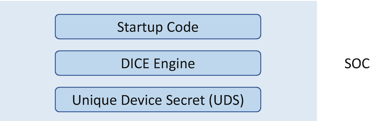
DICE SOC
The equation is
CDI = HMAC(UDS, Hash(Code))

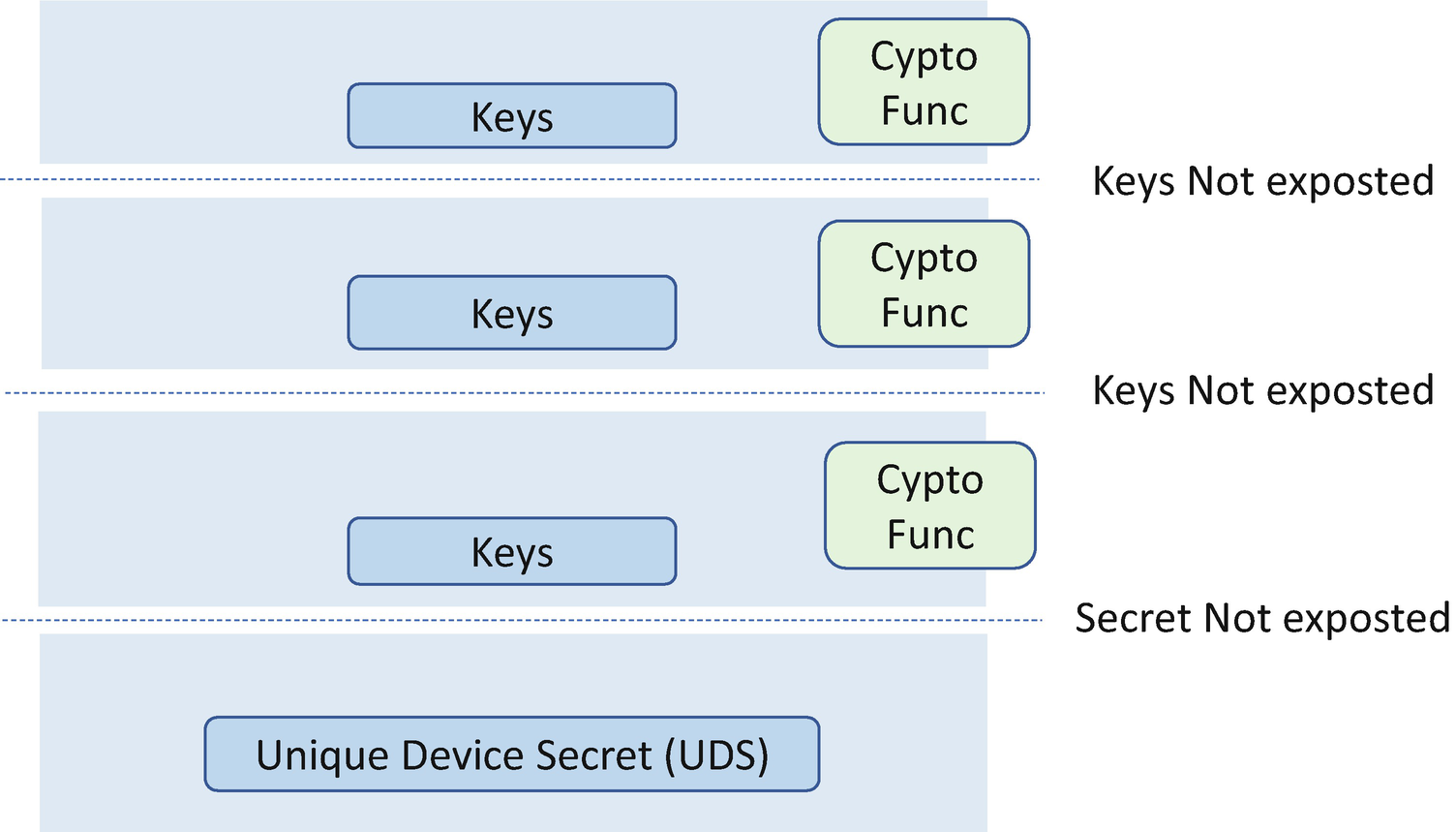
Layered DICE Architecture
The CDI is generated from SOC hardware with the UDS and the hash of the startup code. Then the DICE core (layer 0) uses the CDI to derive a device ID key pair. The device ID key pair is the identifier of the device, and it should not be disclosed outside of the DICE core. In order to prove knowledge of the private portion of the device ID without exposing the device ID key, the DICE core needs to generate a new key pair for the next layer. This key pair is referred to as the alias key. The alias key pair is derived from the CDI and the identity of the next layer – the device firmware. This key can be passed to the device firmware layer, and the private portion of the key can be used during the device firmware lifetime. The device firmware needs to make sure the alias key is not disclosed outside of the device firmware. The device firmware update will cause the alias key pair update without impacting the device ID key pair. The DICE core also creates the certificate for the alias key signed with the device ID private key and a self-signed device ID certificate. The device ID certificate does not change for the life of the device, while the alias key certificate changes more frequently when the firmware is updated.
The DICE core implementation can be easily extended to a multilayered boot. Each layer creates a new alias key and an alias certificate for the next layer. The alias certificates issued to the next layer are signed with the alias key granted to the current layer.

TPM Key Protection
DICE Key Protection
The DICE specification is still under development. Please refer to the latest DICE documentation for more details.
Case Study
Now, let’s take a look at some real cases for the SRTM implementation.
Measured Boot Support in UEFI BIOS

PCR Mapping in UEFI BIOS
PCR Measurement in UEFI BIOS
PCR Index | TCG Defined Usage | UEFI Example |
|---|---|---|
0 | CRTM, Host Platform Code | CRTM, platform firmware (PEI, DXE, SMM, UEFI Boot Services, UEFI runtime services, Embedded Driver), presence of non-host firmware (type, version) |
1 | Host Platform Configuration | CMOS configuration, UEFI boot variable, UEFI setup variable, ACPI table, SMBIOS table, Microcode, chassis |
2 | UEFI driver code | Option ROM, device firmware, non-host firmware |
3 | UEFI driver configuration and data | Option ROM configuration, device firmware configuration, non-host firmware configuration |
4 | UEFI Boot Manager Code | OS loader |
5 | Boot Manager Code Configuration and Data | UEFI Boot Action, GPT partition |
6 | Host Platform Manufacturer Specific | N/A |
7 | Secure boot policy | UEFI secure boot policy (PK, KEK, db, dbx, dbt, dbr, secure boot state, audit mode, deploy mode), security state, debug state |
The system firmware contributes most of the PCR measurements. Any running code on the non-host firmware or device should also be measured. For a device, there might be two different kinds of code – the system firmware and option ROMs. The system firmware means the code running on the device which provides the services to the host. The option ROMs are a special type of firmware that runs on the host side and works as a device driver in the BIOS environment before the operating system driver is available. Typically, PCI storage cards, PCI graphic cards, or PCI network cards may have an option ROM.
After the system firmware finishes initialization, it measures the OS loader and transfers control to the OS loader. Then the OS loader measures the OS kernel and the boot parameters, and then the OS loader transfers control to the OS kernel. In order to let the OS loader reuse the measurement code from the BIOS, the BIOS needs to expose a measurement interface, such as the legacy INT 1A TCPA service, the EFI_TCG_PROTOCOL for TPM1.2, or the EFI_TCG2_PROTOCOL for TPM2.0.
The BIOS also needs to provide a way to let the OS get the TCG event log. For TPM1.2, the event log is passed in the TCPA ACPI table. TPM2.x supports multiple hash algorithms, whereas a TPM1.2 only supports the SHA1 hash algorithm. When TPM2.x was introduced, TCG added a second type of event log. One is compatible with TPM1.2 and only supports SHA1. The other uses a new format and supports multiple hash algorithms. Today, since SHA1 is deprecated, only the new format of the event log is used. It can be retrieved by TCG2_PROTOCOL’s GetEventLog() function or from the TPM2 ACPI table.
PCR Measurement Step During OS Boot
Steps | Legacy OS (Windows/Linux) | UEFI Windows | UEFI Linux | Customized BIOS/OS |
|---|---|---|---|---|
The BIOS will measure the “OS bootloader.” | The legacy BIOS measures the Master Boot Record (MBR) content. | The UEFI BIOS measures bootmgr.efi. | The UEFI BIOS measures grub.efi. | BIOS internal behavior. It should know where the OS loader is and what the format is. It needs to measure it before passing the control to it. |
BIOS exposes “the measurement service” to the OS bootloader. | INT 1A TCPA (16-bit real mode) for TPM1.2. | EFI_TCG_PROTOCOL. HashLogExtendEvent() for TPM1.2 EFI_TCG2_PROTOCOL. HashLogExtendEvent() for TPM2.0. | EFI_TCG_PROTOCOL. HashLogExtendEvent() for TPM1.2 EFI_TCG2_PROTOCOL. HashLogExtendEvent() for TPM2.0. | It might not be required, if the OS loader knows how to interact with the measurement device. |
BIOS exposes the TCG event log to OS. | TCPA ACPI table for TPM1.2. | TCPA ACPI table for TPM1.2 EFI_TCG2_PROTOCOL. GetEventLog() and FINAL_EVENTS_TABLE or TPM2 ACPI table for TPM2.0. | TCPA ACPI table for TPM1.2 EFI_TCG2_PROTOCOL. GetEventLog() and FINAL_EVENTS_TABLE or TPM2 ACPI table for TPM2.0. | ACPI table or a private interface may be used. |
The OS bootloader may use the BIOS measurement service to “extend the OS kernel” before the OS driver is ready to use. | The legacy bootloader (MBR and extension) measures the rest of the OS kernel. | bootmgr.efi measures the Windows OS kernel. | grub.efi measures the command and kernel file. | The vendor-specific loader measures the vendor-specific kernel. |
Once the control is transferred to the OS, the BIOS service is not available. The OS will use its own driver to extend more components. | Legacy OS kernel measures the rest. | Windows OS kernel measures the rest. | Linux OS kernel measures the rest. | Kernel measures the rest. |
“A Tour Beyond BIOS: Implementing TPM2 Support in EDKII” describes more details about TPM support in the EDK II BIOS.
Intel Boot Guard
PCR Measurement in Intel Boot Guard
PCR Index | TCG Defined Usage | Boot Guard ACM Example |
|---|---|---|
0 | CRTM, Host Platform Code | Detail: ACM Policy Status (measured boot, verified boot), ACM Secure Version Number (SVN), ACM Signature, KeyManifest Signature, BootPolicyManifest Signature, Initial Boot Block (IBB) Hash |
1 | Host Platform Configuration | N/A |
2 | UEFI driver code | N/A |
3 | UEFI driver configuration and data | N/A |
4 | UEFI Boot Manager Code | N/A |
5 | Boot Manager Code Configuration and Data | N/A |
6 | Host Platform Manufacturer Specific | N/A |
7 | Secure boot policy | Authorities: ACM Policy Status (measured boot, verified boot), ACM Secure Version Number (SVN), ACM Public Key Hash, KeyManifest Public Key Hash, BootPolicyManifest Public Key Hash |
Since the Boot Guard ACM needs to use a TPM, it must start the TPM. If the Boot Guard ACM starts the TPM in locality 3, a TCG_EFI_STARTUP_LOCALITY_EVENT must be created to record such information.
Measured Boot Support in coreboot
PCR Measurement in coreboot
PCR Index | TCG Defined Usage | coreboot Example |
|---|---|---|
0 | CRTM, Host Platform Code | Google VBoot GBB flags |
1 | Host Platform Configuration | Google VBoot GBB HWID |
2 | UEFI driver code | Core root-of-trust for Measurement which includes all stages, data, and blobs, such as COREBOOT CBFS (boot block, fallback/verstage), FW_MAIN CBFS (fallback/romstage, fspm, fallback/postcar, fallback/ramstage, cpu_microcode_blob, fsps, vbt, fallback/dsdt.aml, fallback/payload), RO_VPD, GBB, SI_DESC, SI_GBE |
3 | UEFI driver configuration and data | Runtime data like hwinfo.hex or MRC cache, such as SI_ME, RW_NVRAM |
4 | UEFI Boot Manager Code | N/A |
5 | Boot Manager Code Configuration and Data | N/A |
6 | Host Platform Manufacture Specific | N/A |
7 | Secure boot policy | N/A |
Similar to UEFI, the coreboot solution uses the ACPI table to pass the event log information. The TCPA ACPI table includes the event log information for TPM1.2, and the TPM2 ACPI table includes the event log information for TPM2.0.
Windows BitLocker
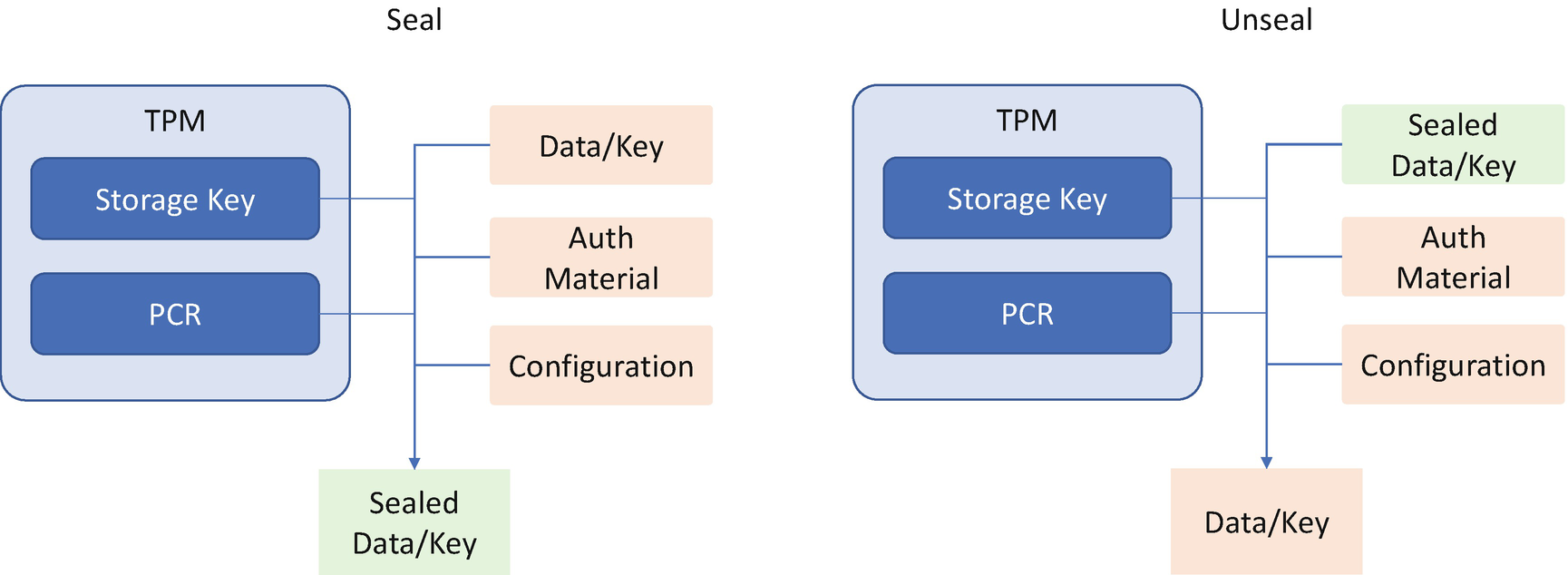
TPM Seal/Unseal with PCR
PCR Measurement in BitLocker
PCR Index | Windows Operating System |
|---|---|
0 | Core System Firmware executable code |
1 | Core System Firmware data |
2 | Extended or pluggable executable code |
3 | Extended or pluggable firmware data |
4 | Boot manager/Legacy MBR |
5 | GPT/Partition Table/Legacy MBR Partition Table |
6 | Resume from S4 and S5 Power State Events |
7 | Secure boot state |
8 | Reserved/Legacy NTFS Boot Sector |
9 | Reserved/Legacy NTFS Boot Block |
10 | Reserved/Legacy Boot Manager |
11 | BitLocker access control |
12 | Data events and highly volatile events |
13 | Boot Module Details |
14 | Boot Authorities |
15~23 | Reserved |
Grub
PCR Measurement in Grub
PCR Index | Grub |
|---|---|
8 | Grub command line: All executed commands (including those from configuration files) will be logged and measured as entered with a prefix of “grub_cmd:” |
Kernel command line: Any command line passed to a kernel will be logged and measured as entered with a prefix of “kernel_cmdline:” | |
Module command line: Any command line passed to a kernel module will be logged and measured as entered with a prefix of “module_cmdline:” | |
9 | Files : Any file read by Grub will be logged and measured with a descriptive text corresponding to the filename. |
Linux Integrity Measurement Architecture
The Linux Integrity Measurement Architecture is designed for kernel integrity. The goal of kernel integrity is to detect if files have been modified accidentally or maliciously, compare a file’s measurement value to the golden value, and enforce local file integrity.
Integrity Measurement Architecture (IMA) was first introduced in Linux 2.6.30 kernel. It includes three components: IMA-measurement, IMA-appraisal, and IMA-audit. IMA maintains a list of runtime measurements and the aggregated PCR values in the TPM. The benefit of having the aggregated values in the TPM is that if the list is modified, then the modification can be detected by reconstructing the PCR values. The IMA uses the PCR[10] to record the measurement of the files.
OpenPOWER Trusted Boot
PCR Measurement in OpenPOWER
PCR Index | TCG Defined Usage | OpenPOWER Example |
|---|---|---|
0 | CRTM, Host Platform Code | Hostboot and other firmware components |
1 | Host Platform Configuration | Configuration data and firmware container metadata |
2 | UEFI driver code | IBM Coherent Accelerator Processor Interface (CAPI) code |
3 | UEFI driver configuration and data | IBM Coherent Accelerator Processor Interface (CAPI) data |
4 | UEFI Boot Manager Code | Open Power Abstraction Layer (OPAL) firmware, static OS (Linux kernel and initramfs) |
5 | Boot Manager Code Configuration and Data | TPM enabled flags, Open Power Abstraction Layer (OPAL) container metadata, boot sequence, static OS configuration (Linux kernel command line) |
6 | Host Platform Manufacturer Specific | Reserved |
7 | Secure boot policy | Reserved |
Supply Chain Validation
A supply chain is a network between a company and its suppliers to produce and distribute a specific product to the final buyer. An attacker may tamper with the components (hardware, firmware, or software) after the supplier ships the product and before the final buyer receives the product. How can the buyer make sure the product received is the product shipped from the supplier?
NIST SP800-155 provides guidelines for the BIOS integrity measurement, reporting, collection, and transmission. The Measurement Assessment Authority (MAA) can judge if the system is as expected, which has been discussed in the Verification and Attestation section. Besides the reference measurements, TCG also defines the platform certificate which should be provided by an OEM and/or VAR. This certificate describes the EK certificate, platform attributes such as platform manufacture string, platform model, platform version, and TPM and platform assertions such as MeasurementRootType. That concept is shown in Figure 7-6.
The National Security Agency (NSA) open sourced a prototype named Host Integrity at Runtime and Startup (HIRS) to illustrate the supply chain validation capability. The platform manufacturer creates the Base Platform Certificate. The system integrators and Value-Added Resellers create the Delta Platform Certificate. An Attestation Certificate Authority (ACA) can provision the TPM with an Attestation Identity Credential (AIC). At runtime, the ACA can perform the Endorsement Credential Certificate Chain Validation to verify if the endorsement key used by the TPM is placed there by the Original Equipment Manufacturer (OEM) and the Platform Credential Certificate Chain Validation to verify the provenance of the system's hardware components, such as the motherboard and chassis, by comparing measured component information against the manufacturers, models, and serial numbers listed in the Platform Credential.
Intel Transparent Supply Chain is another implementation for supply chain verification. It enables platform- and component-level traceability for Intel vPro systems.
Project Cerberus
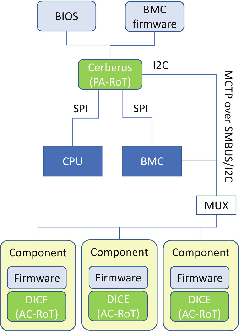
Cerberus Architecture
Measurement = HMAC(Seed, Hash(Code))
The seed is typically derived from the measurement of the previous layer or the alias key certificate. As such, the final measurement is a chained measurement of all the layers.
Cerberus RoT Command List
Register Name | RoT | Description |
|---|---|---|
Firmware Version | PA/AC | Retrieves firmware version information. |
Device Capabilities | PA/AC | Retrieves device capabilities. |
Device ID | PA/AC | Retrieves device ID. |
Export Certificate | PA/AC | Exports certificate signing request (CSR). |
GET_DIGESTS | PA/AC | PA-RoT retrieves session information. |
GET_CERTIFICATE | PA/AC | PA-RoT sets session variables based on Session Query. |
CHALLENGE | PA/AC | PA-RoT retrieves and verifies AC-RoT certificate. |
Key Exchange | PA | Exchanges pre-master session keys. |
Get Log | PA | Retrieves debug, attestation, and tamper log. |
Platform Configuration Register | PA | Returns the Platform Measurement. |
Extend Platform Configuration Register | PA | Extends Platform Measurements. |
Unseal Message | PA/AC | Unseals attestation challenges. |
Unseal Message Result | PA/AC | Gets unsealing status and result. |
Microsoft Azure Sphere: Pluton
Microsoft Azure Sphere is a secured high-level application platform with built-in communication and security features for Internet-connected devices. It comprises a secured, connected, crossover microcontroller unit (MCU). The Pluton secure subsystem is the tamper-resistant hardware-based root-of-trust for Azure Sphere. It has a cryptographic engine and provides services for secure boot verification.
Besides secure boot, the Pluton secure subsystem also supports measured boot and remote attestation in silicon. During boot, the Pluton records the hash of all boot components. When an Azure Sphere device connects to the Azure Sphere Security Service (AS3), the device verifies the server authentication by using a locally stored certificate. At the same time, AS3 also authenticates the device itself via remote attestation. The Pluton returns the hash value and the signature of the hash value with the attestation key. Because AS3 has the device attestation key, then the AS3 can determine whether the device is authentic and whether the device boots with genuine software.
Cisco Trust Anchor
Cisco uses Trust Anchor technology to provide the foundation for the Cisco trustworthy system. Besides secure boot, the Cisco Trust Anchor Module (TAm) can be used to verify that the hardware is authentic. The OS can check the TAm for a secure unique device identifier (SUDI) that could have come only from Cisco. The SUDI is permanently programmed into the TAm in the manufacturing processes to support the supply chain verification.
Attack and Mitigation
Now, let’s take a look at some real cases for the attacks to the SRTM and mitigation.
Attack on Completeness
Completeness is the biggest challenge of trusted computing. The final solution must measure any mutable component and configuration for the verification. In practice, some firmware might not measure all the firmware code. A change in that code would not be detected. Also, some firmware might not measure all the security-related settings. If the security settings were turned off, it would not be detected.
Non-host firmware is also problematic. Researchers have demonstrated the capability to replace the keyboard firmware, embedded controller (EC) firmware, baseboard management controller (BMC) firmware, battery firmware, and other system board firmware. As such, the hacker may record the user’s keystrokes, remotely control the system, or control the battery charging. However, those devices’ firmware might not be measured in the most current systems.
Take Stuxnet as another example. The virus Stuxnet is typically introduced into the supply network via an infected USB flash drive by a person with physical access to the system. The worm then travels across the network, scanning software on computers controlling a programmable logic controller (PLC). Stuxnet introduces the infected rootkit onto the PLC modifying the code and giving unexpected commands to the PLC while returning a loop of normal operation value feedback to the users. The questions are as follows: Should we measure if the USB port is blocked? Should we measure the USB flash device firmware? Should we measure the content on the USB flash device? Should we measure the software which controls the PLC device? Should we measure the PLC code?
Any missing part of the measurement is a potential attack point.
Attack S3 Resume

S3 Resume Attack
Hijack the Device
The TPM is attached to the platform board. It may be connected via the Low Pin Count (LPC) bus, Serial Peripheral Interface (SPI) bus, or I2C bus. The TCG Platform TPM Profile Specification describes the TPM hardware interface. Currently hackers have demonstrated how to hijack the LPC bus or I2C bus between the TPM and the platform board. A high-assurance platform may choose to not expose the TPM connection. Or if the TPM connection is exposed, then all the commands need to use authorization sessions, and the TPM EK certificate verification is required.
Attack the TPM Device
By definition, the TPM device should be tamper-resistant. However, the TPM implementation may have security flow. For example, there have been examples of firmware TPM (fTPM) implementations with security issues related to remote code execution via crafted EK certificate. The fTPM or discrete TPM (dTPM) implementations have timing and lattice vulnerabilities.
Dynamic Root-of-Trust for Measurement (DRTM)
The biggest problem for SRTM is that the platform must make sure every required component is measured every time the platform boots. One missing measurement may cause the trust chain to be broken.

DRTM vs. SRTM Boot Flow
CPU-Based Dynamic Root-of-Trust

DRTM Launch Flow

DRTM Application Processor Launch Flow
DRTM PCR Measurement
PCR Index | TCG Defined Usage |
|---|---|
17 | Detail: Used to record detailed measurements of all components involved in the DRTM process, including components provided by the chipset manufacturer, the platform manufacturer, and the operating system vendor. |
18 | Authorities: Used to record the authority measurements of the chipset manufacturer components and the platform manufacturer components. |
19 | DLME.Authority: Used to record the authority of the DLME launched at the end of the DRTM process. |
20~22 | For the DLME/MVMM. |
The measurement report and the verification flow of DRTM are similar to the ones of SRTM. DRTM extends the TPM PCR value and generates the event log for future attestation.
A system may choose to use the SRTM solution or the DRTM solution based upon need. In SRTM, the system needs to add the OEM BIOS into the TCB or Chain-of-Trust. If the first instruction is the BIOS reset vector, then the initial boot block (IBB) of the BIOS is the C-SRTM. In this case, the IBB needs to measure itself and the rest of the BIOS into a PCR. If we don’t trust the OEM BIOS IBB, a processor-based C-SRTM may be used, such as Intel Boot Guard or AMD secure boot.
If we don’t trust the OEM BIOS, then we may use DRTM. The DRTM solution requires a measured virtual machine monitor (MVMM) and relies on the measured VMM monitoring the system.
S3 Resume
The S3 resume in DRTM is different from SRTM. In SRTM, before a platform enters S3 state, the OS sends TPM_Shutdown(STATE) to let the TPM save the context. When resuming from S3, the BIOS sends the TPM_Startup(STATE) to let the TPM restore the context. The TPM context includes all the SRTM PCRs, but does not include the DRTM PCRs. After resume, all DRTM PCRs are reset to 0xFF.
The DCE preamble must rerun the DRTM instruction to enter the DCE. The DCE must recheck the environment and remeasure itself and the DLME into TPM. Later the DLME must also remeasure the required components and restore the original execution environment. The whole process is very similar to the normal boot.
Care must be taken when the dynamic OS calls DLME_Exit. The DLME_Exit does not modify any PCR values. As such, the dynamic OS must extend some garbage value to the DRTM PCR to prevent the untrusted environment from unsealing data protected by DRTM PCR values.
The DLME must also make sure there is no secret in the memory. If there is a secret that needs to be saved, the DLME may choose to seal the data to the TPM or encrypt the data and seal the key into TPM.
DEC’s Execution Environment
The DCE is responsible for ensuring the platform is in a trustworthy state as defined by the CPU, chipset, and platform manufacturer. For example, when the DCE is executed, then all interrupts must be disabled, including external interrupts, non-maskable interrupts, and the system management interrupt. Only the Boot Strap Processor (BSP) is allowed to execute this dynamic launch instruction. All other application processors (APs) must be halted. The Direct Memory Access (DMA) controller should be stopped, and the DCE process will prohibit the DMA access to the critical memory involved in the DCE state transition.

DLME and STM
Direct Memory Access (DMA) devices are devices that can access the system memory with DMA. The DMA device is outside of the Trust Computing Base (TCB) in DRTM. The DCE should turn off the DMA for the device or set up a I/O memory management unit (IOMMU) to block the DMA from the device.
If a hardware device can be restricted from accessing the platform, DCE, or DLME’s memory or I/O resource, it is called a peripheral device. On the other hand, if a hardware device cannot be restricted from accessing the platform, DCE, or DLME’s memory or I/O resource, it is called a non-host platform (NHP). The NHP usually consists of a separate CPU or microcontroller that executes the firmware and the software. If the NHP is immutable, it is called fixed NHP. If the NHP is mutable, it is called an updatable NHP. If the state of an updatable NHP can be reliably reported by the DCE, then it is a DCE-verifiable NHP. If the DCE cannot reliably report on an NHP, then it is a DCE-unverifiable NHP. The DCE shall measure or verify the DCE-verifiable NHP. If an NHP is unverifiable, the DCE has to trust it, and the NHP update mechanism must include signing verification.
Hot Plug
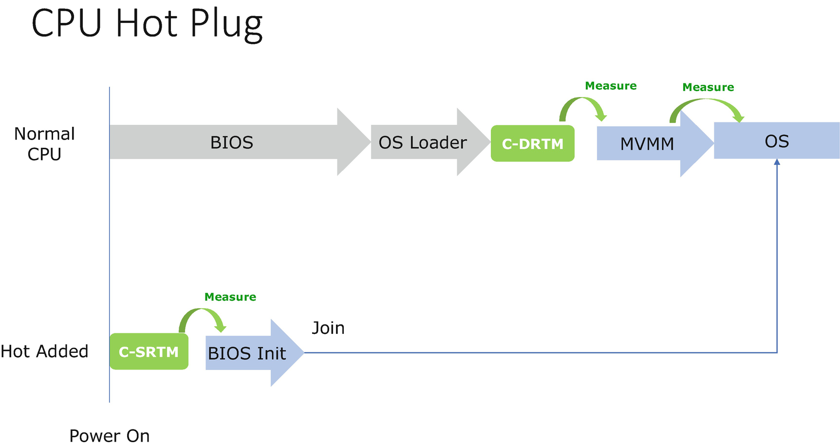
DRTM Hot Plug Support
Case Study
Now, let’s take a look at some real cases for the DRTM implementation.
Intel Trusted Execution Technology (TXT)
PCR Measurement in Intel TXT
PCR Index | TCG Defined Usage | Intel TXT Example |
|---|---|---|
17 | Detail | BIOS-ACM registration information, SCRTM status code, platform owner (PO) policy PolicyControl field, all matching elements of the policy, STM, OsSinit table capability field, MLE |
18 | Authorities | Public key of SINIT-ACM, SCRTM status code, OsSinit table capability field, platform owner (PO) policy PolicyControl field, all matching elements of the Launch Control Policy (LCP) |
19 | DLME.Authority | N/A |
Besides platform hardware status check, the SINIT-ACM uses a Launch Control Policy (LCP) to verify if the software launched meets the predefined criteria, such as ACM version, STM enabling state, and MLE hash. The LCP is also extended to PCRs 17 and 18. The configuration of LCP is complicated. Please refer to Intel 64 and IA-32 Architectures Software Developer Manuals and Intel TXT software development guide for details.
AMD Secure Virtual Machine (SVM) Architecture
PCR Measurement in AMD SVM
PCR Index | TCG Defined Usage | AMD SVM Example |
|---|---|---|
17 | Detail | Secure Loader Block (SLB) |
18 | Authorities | N/A |
19 | DLME.Authority | N/A |
Please refer to AMD64 Architecture Programmer’s Manual for more detailed information.
DRTM Concept Mapping
TCG | Intel TXT | AMD SVM |
|---|---|---|
Dynamic launch (DL) event | GETSEC[SENTER] | SKINIT |
DRTM Configuration Environment (DCE) | SINIT Authenticate Code Module (ACM) | Secure Loader (SL) |
Dynamically Launched Measured Environment (DLME) | Measured Launch Environment (MLE) | Secure kernel (SK) |
tboot
Both Intel and AMD support the DRTM DCE component. Now the question is, where is the DLME component? Trusted Boot (tboot) project is the first open source DLME project that may be used in Xen or Linux.
PCR Measurement in tboot
PCR Index | TCG Defined Usage | tboot Example |
|---|---|---|
17 | Detail | tboot policy control value, hash of tboot policy, hash of the first module in grub.conf (e.g., Xen or Linux kernel), hash of all modules (other than the first one) |
18 | Authorities | tboot policy control value, hash of tboot policy |
19 | DLME.Authority | N/A |

tboot Flow
Currently tboot only supports Intel TXT, but there are other open source projects that support AMD SVM, such as OSLO – The Open Secure Loader – or TrenchBoot. tboot only supports Linux and does not support Windows.
TrenchBoot

TrenchBoot Flow
Windows Defender System Guard Secure Launch
In 2019, Microsoft announced the “Windows Defender System Guard Secure Launch” in Windows 10 version 1809. This is the first official DRTM implementation on the Windows operating system. It allows untrusted UEFI firmware code to boot the system and securely transfer to the Windows OS in a trusted and measured state. This seems to be the implementation for the Next-Generation Secure Computing Base (NGSCB), code name Palladium, which was announced in 2003.
Attack and Mitigation
Now, let’s take a look at some real cases for the attack to the DRTM and related mitigations.
Malicious Software Input for DCE
The DCE plays an important role in establishing the DRTM. It must check the current running environment, and it must not trust any input from the system because it is the DCE that creates the root-of-trust environment. However, since DCE is also software, it may have vulnerabilities. It is an attack surface in DRTM.
Take Intel SINIT-ACM as an example. The SINIT-ACM needs to parse the DMA remapping (DMAR) ACPI table to set up the I/O memory management unit (IOMMU) to protect the memory from DMA attack. The DMAR ACPI table is untrusted input, and it may be modified by the malicious attacker. However, the DMAR table is used before validating the address. As such, the attacker may control the copied memory length and override the Intel Trusted Executable Technology (TXT) heap and SINIT-ACM itself.
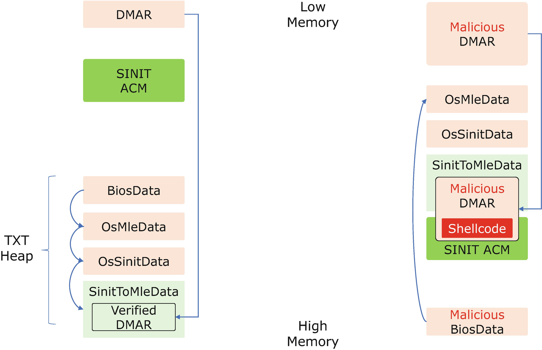
SINIT-ACM Attack via the DMAR ACPI Table
The right-hand side is how the flow is attacked. Because the BiosData, OsMleData, and OsSinitData on the TXT heap are untrusted, the attacker may give a negative value for the BiosData size. It makes the SINIT-ACM calculate that the OsMleData and OsSinitData are above the SINIT-ACM. SINIT-ACM also puts the SinitToMleData above the SINIT-ACM. With the DMAR table hacked, the SINIT-ACM copies the malicious DMAR into SinitToMleData, because the check of the DMAR table’s length is missing. The SINIT-ACM copies the big chunk of the DMAR table and overwrites the beginning of the SINIT-ACM with shellcode.
In order to prevent this software attack, the DCE must carefully check all external input.
Malicious Hardware Configuration for DCE

SINIT-ACM Attack via MCH-BAR Reconfiguration
The MCH-BAR is 36 bits according to the silicon definition. In most systems, this MCH-BAR is configured below 4GB because the early boot code runs in 32-bit protected mode. Unfortunately, the SINIT-ACM only checks the lower 32 bits of the MCH-BAR. If the attacker assigns some real value above 4GB but allocates a fake IOMMU engine and reports it in the fake MCH configuration below 4GB, then the check may pass, but the IOMMU engine does not work to prevent DMA attack. See the right-hand side of Figure 7-24.
The DCE must not make any assumptions on the hardware configuration, and it must read the full register value to do the check.
Attack the DLME Completeness
The completeness problem may also exist in DRTM. It is a little better because DRTM measures less components than SRTM. But if some critical component is missing, the trust chain is also broken.

tboot Attack – Image Layout

tboot Attack – PCR Forge
Attack via SMM
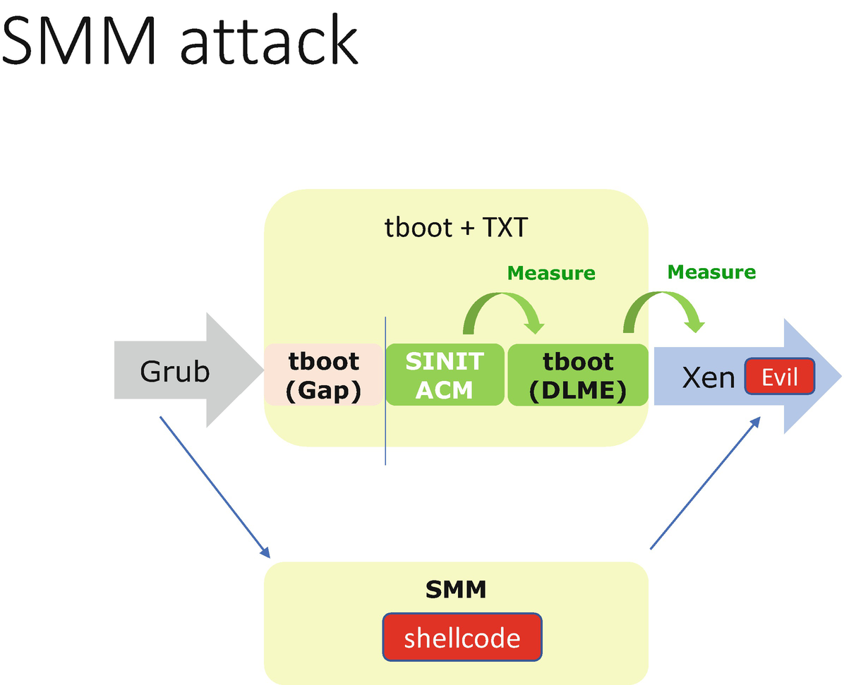
Intel TXT Attack Via SMM
Attack via Hardware Configuration
We will discuss malicious hardware configuration in Chapter 18.
The DCE must check the hardware configuration and register locks.
Attack via Peripheral or NHP
We will discuss the DMA attack in Chapter 8.
The DCE must enable DMA protection when it executes.
TCG Memory Overwrite
Many people assume that a computer’s memory is erased immediately when it loses power. However, typical DRAMs lose their contents gradually over a period of seconds, even for minutes or hours if the chips are kept at low temperatures. As such, the attackers may suddenly reset the system, giving the trusted OS no opportunity to clear the secrets in the memory. Then on the next boot, after the memory controller is initialized, a malicious program may read the contents of the memory to steal the secret.
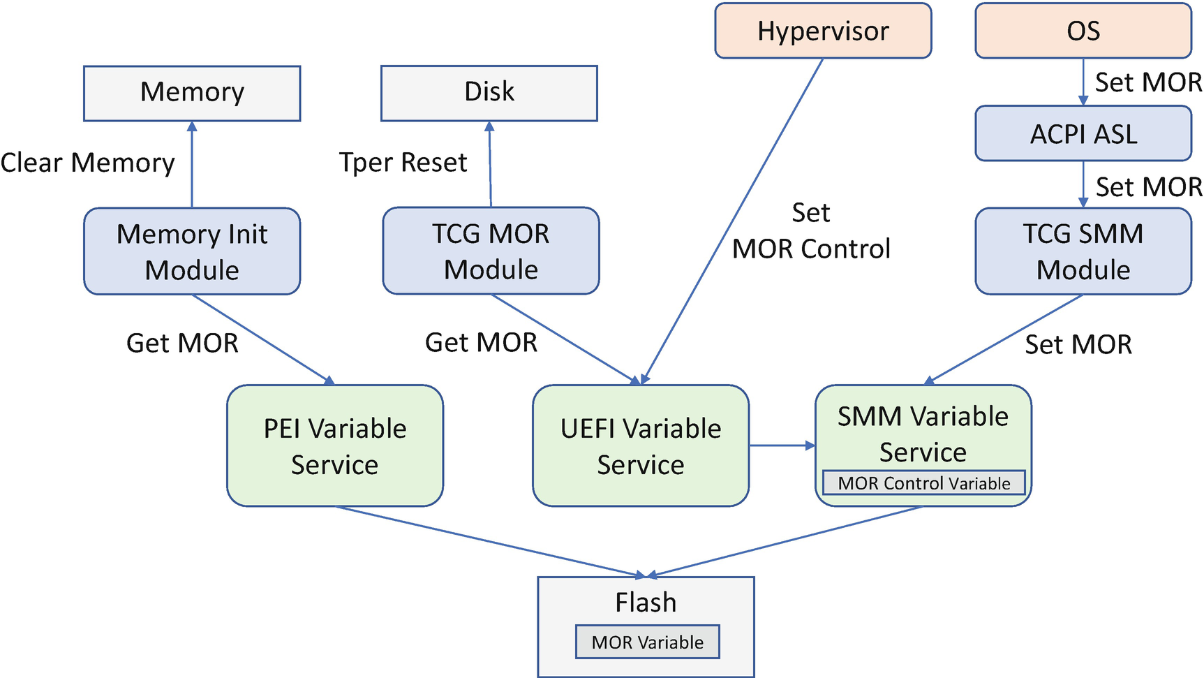
In order to mitigate the reset attack, the TCG defines a memory overwrite mechanism. When the BIOS boots, the BIOS sets a UEFI variable MOR as 0 to indicate no memory overwrite request. If the OS wants to create the secret in the memory, the OS writes the MOR variable to 1 to indicate that there is a secret and the memory needs to be overwritten on the next boot. If the system shuts down normally, the OS needs to remove the secret from the memory and reset the MOR variable to 0. This is to save the boot time since overwriting all system memory may be time-consuming work.

MOR Flow
Secure MOR
If the system includes a hypervisor and an OS, things become more complicated. The secret might be set up by the hypervisor, but the OS may have capability to read and write the UEFI variable, including the MOR variable. Even if the hypervisor sets the MOR variable to indicate a memory overwrite request, the malicious OS may clear the MOR variable later and trigger a reset to read the secret from the hypervisor.

Secure MOR Flow
MOR for Storage
If there is an MOR request, the BIOS needs to not only clear the memory but also send the TCG Trusted Peripheral (TPer) Reset command to the storage device through the IEEE 1667 protocol or through the native TCG storage protocol. This TPer Reset command is to make sure the protected ranges are locked on the abnormal reset.
Memory Overwrite Component
Attack and Mitigation
Now, let’s take a look at some real cases for the attack to the TCG memory overwrite and mitigation.
Default MOR Policy
The BIOS code needs to read the MOR variable to figure out if there is memory overwrite request or not. There might be a case that the BIOS code cannot find any MOR variable. A bad BIOS implementation may interpret this as no memory overwrite request. That gives the attacker a chance to manipulate the flash region to make the variable not available to the BIOS. Then the memory overwrite will not happen. The right behavior shall be to always treat the MOR request as present if the MOR variable is not available.
TCG Physical Presence Configuration
The TCG specification defines the physical presence interface, which lets the user configure the TPM. We will discuss this in Chapter 10.
TCG Storage
TCG defines a set of storage extensions to allow a physical presence interface which lets users configure the TCG storage. We will discuss this in Chapter 10.
Summary
In this chapter, we discussed the two forms of trusted boot – static root-of-trust and dynamic root-of-trust. Both of them are implemented in the industry. We compared trusted boot with secure boot. They are used for different purposes. In the next chapter, we will discuss device firmware security.
References
Book
[B-1] Sean W. Smith, Trusted Computing Platforms: Design and Applications, Springer, 2004
[B-2] Graeme Proudler, Liqun Chen, Chris Dalton, Trusted Computing Platforms: TPM2.0 in Context, Springer, 2016
[B-3] Ariel Segall, Trusted Platform Modules: Why, when and how to use them, The Institution of Engineering and Technology, 2016
[B-4] Will Arthur, David Challener, A Practical Guide to TPM2.0, Apress, 2015
[B-5] David Challener, Kent Yoder, Ryan Catherman, David Safford, Leendert Van Doom, A Practical Guide to Trusted Computing, IBM Press, 2008
[B-6] William Futral, James Greene, Intel Trusted Execution Technology for Server Platforms: A Guide to More Secure Datacenters, Apress, 2013
[B-7] David Grawrock, Dynamics of a trusted platform: a building block approach, Intel Press, 2009
[B-8] David Grawrock, The Intel Safer Computing Initiative Building Blocks for Trusted Computing, Intel Press, 2006
Conference, Journal, and Paper
[P-1] David Safford, Mimi Zohar, Reiner Sailer, “Using IMA for Integrity Measurement and Attestation,” IBM 2009, available at https://blog.linuxplumbersconf.org/2009/slides/David-Stafford-IMA_LPC.pdf
[P-2] Jiewen Yao, Vincent Zimmer, “A Tour Beyond BIOS with the UEFI TPM2 Support in EDKII,” Intel whitepaper, 2014, available at https://github.com/tianocore/tianocore.github.io/wiki/EDK-II-Security-White-Papers
[P-3] Tom Dodson, “Intel Transparent Supply Chain process,” in Software and Supply Chain Assurance Forum 2017, available at https://csrc.nist.gov/CSRC/media/Projects/Supply-Chain-Risk-Management/documents/ssca/2017-winter/TuePM1_3_%20Intel.pdf
[P-4] Eduardo Cabre, Tom Dodson, “Secure Your Business: End-to-End Supply Chain Traceability,” Intel Whitepaper 2019, available at https://tsc.intel.com/documents/TSCBlockchain_white_paperFINAL.PDF
[P-5] Paul England, Andrey Marochko, Dennis Mattoon, Rob Spiger, Stefan Thom, David Wooten, “RIoT – A Foundation for Trust in the Internet of Things,” Microsoft Whitepaper 2016, available at www.microsoft.com/en-us/research/publication/riot-a-foundation-for-trust-in-the-internet-of-things/
[P-6] Ronald Aigner, Paul England, Kevin Kane, Andrey Marochko, Dennis Mattoon, Rob Spiger, Stefan Thom, and Greg Zaverucha, “Device Identity with DICE and RIoT: Keys and Certificates,” Microsoft Whitepaper 2017, available at www.microsoft.com/en-us/research/publication/device-identity-dice-riot-keys-certificates/
[P-7] Rob Spiger, Stefan Thom, “Trusted Computing and Securing Devices,” in International Trusted Computing and Security Innovation Summit 2017, available https://trustedcomputinggroup.org/wp-content/uploads/3.4_Trusted-Computing-and-Securing-Devices-2017.04.06-Final.pdf
[P-8] Bryan Kelly, “Project Cerberus Hardware Security,” in OCP Summit 2018, available at https://f990335bdbb4aebc3131-b23f11c2c6da826ceb51b46551bfafdc.ssl.cf2.rackcdn.com/images/fbbdd5feceb6e6328373417e1ab7c06a13a2ef2c.pdf
[P-9] Doug Stiles, “The Hardware Security Platform Behind Azure Sphere,” in HC30, www.hotchips.org/hc30/1conf/1.13_Microsoft_Hardware_Security_Platform_Behind_Azure_Sphere.pdf
[P-10] Dave Heller, Tim Block, “OpenPOWER secure and trusted boot, Part 1: Using trusted boot on IBM OpenPOWER servers,” IBM Whitepaper, 2017, https://developer.ibm.com/articles/trusted-boot-openpower/
[P-11] Joseph Cihula, “Trusted Boot: Verifying the Xen Launch,” in Xen Summit 2007, available at www-archive.xenproject.org/files/xensummit_fall07/23_JosephCihula.pdf
[P-12] Bernhard Kauer, “OSLO: Improving the security of Trusted Computing,” in USENIX Security 2007, available at http://os.inf.tu-dresden.de/papers_ps/kauer07-oslo.pdf
[P-13] Piotr Krol, “TrenchBoot – Open DRTM implementation for AMD platforms,” in OSFC 2019, https://osfc.io/talks/trenchboot-open-drtm-implementation-for-amd-platforms
[P-14] Daniel Kiper, Daniel P. Smith, “TrenchBoot How to nicely boot system with Intel TXT and AMD SVM,” in Linux Security Summit 2019, https://static.sched.com/hosted_files/lssna19/75/trenchboot_ot_lss_20190815.final.ds.dk.pdf
[P-15] Seunghun Han, Jun-Hyeok Park, “I don’t want to sleep tonight: Subverting Intel TXT with S3 Sleep,” in Blackhat 2018, available at https://i.blackhat.com/briefings/asia/2018/asia-18-Seunghun-I_Dont_Want_to_Sleep_Tonight_Subverting_Intel_TXT_with_S3_Sleep.pdf
[P-16] Seunghun Han, Jun-Hyeok Park, “Finally I can sleep tonight: catching sleep mode vulnerabilities of the TPM with the napper,” in Blackhat 2019, available at http://i.blackhat.com/asia-19/Thu-March-28/bh-asia-Seunghun-Finally-I-Can-Sleep-Tonight-Catching-Sleep-Mode-Vulnerabilities-of-the-TPM-with-the-Napper.pdf
[P-17] Seunghun Han, Wook Shin, Jun-Hyeok Park, and HyoungChun Kim, “A Bad Dream: Subverting Trusted Platform Module While You Are Sleeping,” in USENIX Security 2018, available at www.usenix.org/system/files/conference/usenixsecurity18/sec18-han.pdf
[P-18] Seunghun Han, Jun-Hyeok Park “BitLeaker: Subverting BitLocker with One Vulnerability,” in Blackhat EU 2019, available at https://i.blackhat.com/eu-19/Thursday/eu-19-Han-BitLeaker-Subverting-BitLocker-With-One-Vulnerability.pdf
[P-19] Sven Turpe, Andreas Poller, Jan Steffan, Jan-Peter Stotz, Jan Trukenmuller, “Attacking the BitLocker Boot Process,” International Conference on Trusted Computing, Trust 2009 Trusted Computing, pp 183-196 available at http://citeseerx.ist.psu.edu/viewdoc/download?doi=10.1.1.149.5116&rep=rep1&type=pdf
[P-20] Evan R. Sparks, “A Security Assessment of Trusted Platform Modules,” Computer Science Technical Report TR2007-597, Dartmouth College, 2007, available at https://pdfs.semanticscholar.org/b6a1/802e356f7f900bbbe8b5dc0d8d3aa7fb0ad9.pdf
[P-21] Johannes Winter, Kurt Dietrich, “A Hijacker's Guide to the LPC bus,” in EuroPKI'11 Proceedings of the 8th European conference on Public Key Infrastructures, Services, and Applications, 2011, Pages 176-193, available at https://link.springer.com/content/pdf/10.1007/978-3-642-29804-2_12.pdf, PPT available at https://online.tugraz.at/tug_online/voe_main2.getvolltext?pCurrPk=59565
[P-22] Johannes Winter, Kurt Dietrich, “A hijacker's guide to communication interfaces of the trusted platform module,” in Journal Computers & Mathematics with Applications Volume 65 Issue 5, March, 2013, Pages 748-761, available at www.sciencedirect.com/science/article/pii/S0898122112004634
[P-23] Johannes Winter, “Eavesdropping Trusted Platform Module Communication,” in 4th European Trusted Infrastructure Summerschool, ETISS, 2009, available at http://citeseerx.ist.psu.edu/viewdoc/download?doi=10.1.1.464.6048&rep=rep1&type=pdf
[P-24] Jeremy Boone, “TPM Genie,” in CanSecWest 2018, available at https://github.com/nccgroup/TPMGenie/blob/master/docs/CanSecWest_2018_-_TPM_Genie_-_Jeremy_Boone.pdf
[P-25] Denis Andzakovic, “Extracting BitLocker Keys From a TPM,” in 2019, available at https://pulsesecurity.co.nz/articles/TPM-sniffing
[P-26] K. Chen, “Reversing and exploiting an Apple firmware update,” in Blackhat US 2009, available at www.blackhat.com/presentations/bh-usa-09/CHEN/BHUSA09-Chen-RevAppleFirm-SLIDES.pdf
[P-27] Ralf-Philipp Weinmann, “The hidden nemesis,” in 27th Chaos Communication Congress (27C3) 2010, available at https://comsecuris.com/slides/rpw-27c3-thmbec.pdf
[P-28] Charlie Miller, “Battery Firmware Hacking,” in BlackHat US 2011, available at https://media.blackhat.com/bh-us-11/Miller/BH_US_11_Miller_Battery_Firmware_Public_Slides.pdf
[P-29] Nico Waisman, Matias Sebastian Soler, “The Unbearable Lightness of BMCs,” in BlackHat US 2018, available at http://i.blackhat.com/us-18/Wed-August-8/us-18-Waisman-Soler-The-Unbearable-Lightness-of-BMC.pdf
[P-30] Joanna Rutkowska, Rafal Wojtczuk, “Preventing and Detecting Xen Hypervisor Subversions,” in BlackHat US 2008, available at https://invisiblethingslab.com/resources/bh08/part2-full.pdf
[P-31] Rafal Wojtczuk, Joanna Rutkowska, “Attack Intel TXT,” in BlackHat DC 2009, available at www.blackhat.com/presentations/bh-dc-09/Wojtczuk_Rutkowska/BlackHat-DC-09-Rutkowska-Attacking-Intel-TXT-slides.pdf
[P-32] Rafal Wojtczuk, Joanna Rutkowska, Alexander Tereshkin, “Another Way to Circumvent Intel® Trusted Execution Technology,” in invisiblethingslab whitepaper 2009, available at https://invisiblethingslab.com/resources/misc09/Another%20TXT%20Attack.pdf
[P-33] Rafal Wojtczuk, Joanna Rutkowska, “Attacking Intel TXT via SINIT Hijacking,” in invisiblethingslab whitepaper 2011, available at https://invisiblethingslab.com/resources/2011/Attacking_Intel_TXT_via_SINIT_hijacking.pdf
[P-34] Joseph Sharkey, “Breaking Hardware-Enforced Security with Hypervisors,” in BlackHat US 2016, available at www.blackhat.com/docs/us-16/materials/us-16-Sharkey-Breaking-Hardware-Enforced-Security-With-Hypervisors.pdf
[P-35] J. Alex Halderman, Seth D. Schoen, Nadia Heninger, William Clarkson, William Paul, Joseph A. Calandrino, Ariel J. Feldman, Jacob Appelbaum, and Edward W. Felten, “Lest We Remember: Cold Boot Attacks on Encryption Keys,” in Proc. 17th USENIX Security Symposium 2008, available at www.usenix.org/legacy/event/sec08/tech/full_papers/halderman/halderman.pdf
[P-36] Yuriy Bulygin, “Evil Maid Just Got Angrier: Why Full-Disk Encryption With TPM is Insecure on Many Systems,” in CanSecWest 2013, available at www.c7zero.info/stuff/Evil%20Maid%20Just%20Got%20Angrier.pdf
[P-37] “AMD PSP: fTPM Remote Code Execution via crafted EK certificate,” 2018, https://seclists.org/fulldisclosure/2018/Jan/12
[P-38] Daniel Moghimi, Berk Sunar, Thomas Eisenbarth, Nadia Heninger, “TPM-FAIL: TPM meets Timing and Lattice Attacks,” in 29th USENIX Security Symposium 2020, available at https://arxiv.org/abs/1911.05673
[P-39] Matus Nemec, Marek Sys, Petr Svenda, Dusan Klinec, Vashek Matyas, “The Return of Coppersmith’s Attack: Practical Factorization of Widely Used RSA Moduli,” in ACM CCS 2017, available at https://crocs.fi.muni.cz/_media/public/papers/nemec_roca_ccs17_preprint.pdf, https://crocs.fi.muni.cz/_media/public/papers/ccs-nemec-handout.pdf
[P-40] Paul England, Butler Lampson, John Manferdelli, Marcus Peinado, Bryan Willman, “A Trusted Open Platform,” in IEEE Computer Society 2003, available at www.microsoft.com/en-us/research/wp-content/uploads/2016/11/68-TrustedOpenPlatform.pdf
[P-41] Magnus Nystrom, Martin Nicholes, Vincent Zimmer, “UEFI Networking and Pre-OS Security,” in Intel Technology Journal – UEFI Today: Bootstrapping the Continuum, Volume 15, Issue 1, available at https://www.techonline.com/electrical-engineers/education-training/tech-papers/4231173/UEFI-Networking-and-Pre-OS-Security
Specification and Guideline
[S-1] NIST SP800-155, “BIOS Integrity Measurement Guidelines,” 2011, available at https://csrc.nist.gov/publications/sp800
[S-2] Trusted Computing Group, “Trusted Platform Module Library,” 2016, available at https://trustedcomputinggroup.org/resource/tpm-library-specification/
[S-3] Trusted Computing Group, “TCG PC Client Platform firmware Profile Specification,” 2019, available at https://trustedcomputinggroup.org/resource/pc-client-specific-platform-firmware-profile-specification/
[S-4] Trusted Computing Group, “TCG PC Client Platform TPM Profile (PTP) Specification,” 2019, available at https://trustedcomputinggroup.org/resource/pc-client-platform-tpm-profile-ptp-specification/
[S-5] Trusted Computing Group, “TCG Server Management Domain Firmware Profile,” 2020, available at https://trustedcomputinggroup.org/wp-content/uploads/TCG_ServerManagementDomainFirmwareProfile_v1p00_11aug2020.pdf
[S-6] Trusted Computing Group, “TCG PC Client Platform Reset Attack Mitigation Specification,” 2019, available at https://trustedcomputinggroup.org/resource/pc-client-work-group-platform-reset-attack-mitigation-specification/
[S-7] Trusted Computing Group, “TCG EFI Protocol Specification,” 2016, available at https://trustedcomputinggroup.org/resource/tcg-efi-protocol-specification/
[S-8] Trusted Computing Group, “TCG ACPI Specification,” 2017, available at https://trustedcomputinggroup.org/resource/tcg-acpi-specification/
[S-9] Trusted Computing Group, “TCG Trusted Attestation Protocol (TAP) Information Model,” 2019, available at https://trustedcomputinggroup.org/resource/tcg-tap-information-model/
[S-10] Trusted Computing Group, “TCG Platform Certificate Profile,” 2018, available at https://trustedcomputinggroup.org/resource/tcg-platform-attribute-credential-profile/
[S-11] Trusted Computing Group, “TCG EK Credential Profile,” 2018, available at https://trustedcomputinggroup.org/resource/tcg-ek-credential-profile-for-tpm-family-2-0/
[S-12] Trusted Computing Group, “TCG Reference Integrity Manifest (RIM) Information Model,” 2019, available at https://trustedcomputinggroup.org/wp-content/uploads/TCG_RIM_Model_v1-r13_2feb20.pdf
[S-13] Trusted Computing Group, “TCG PC Client Reference Integrity Manifest,” 2020, available at https://trustedcomputinggroup.org/wp-content/uploads/TCG_PC_Client_RIM_r0p15_15june2020.pdf
[S-14] Trusted Computing Group, “TCG PC Client Platform Firmware Integrity Measurement,” 2019, available at https://trustedcomputinggroup.org/wp-content/uploads/TCG_PC_Client-FIM_v1r24_3feb20.pdf
[S-15] Trusted Computing Group, “Hardware Requirements for a Device Identifier Composition Engine,” 2018, available at https://trustedcomputinggroup.org/resource/hardware-requirements-for-a-device-identifier-composition-engine/
[S-16] Trusted Computing Group, “Implicit Identity Based Device Attestation,” 2018, available at https://trustedcomputinggroup.org/resource/implicit-identity-based-device-attestation/
[S-17] Trusted Computing Group, “Symmetric Identity Based Device Attestation,” 2020, available at https://trustedcomputinggroup.org/resource/symmetric-identity-based-device-attestation/
[S-18] Trusted Computing Group, “TCG DICE Layering Architecture,” 2020, available at https://trustedcomputinggroup.org/resource/dice-layering-architecture/
[S-19] Trusted Computing Group, “TCG DICE Certificate Profile,” 2020, available at https://trustedcomputinggroup.org/resource/dice-certificate-profiles/
[S-20] Trusted Computing Group, “TCG Mobile Trusted Module Specification,” 2010, available at https://trustedcomputinggroup.org/resource/mobile-phone-work-group-mobile-trusted-module-specification/
[S-21] Trusted Computing Group, “TPM 2.0 Mobile Reference Architecture Specification,” 2014, available at https://trustedcomputinggroup.org/tpm-2-0-mobile-reference-architecture-specification/
[S-22] Trusted Computing Group, “TPM 2.0 Mobile Common Profile,” 2015, available at https://trustedcomputinggroup.org/tcg-tpm-2-0-mobile-common-profile/
[S-23] Trusted Computing Group, “TCG TPM 2.0 Mobile Command Response Buffer Interface Specification,” 2014, available at https://trustedcomputinggroup.org/resource/tpm-2-0-mobile-command-response-buffer-interface-specification/
[S-24] Trusted Computing Group, “TCG Runtime Integrity Preservation in Mobile Devices,” 2019, available at https://trustedcomputinggroup.org/wp-content/uploads/TCG_MPWG_RIP_r105_pubrev.pdf
[S-25] Trusted Computing Group, “TCG Remote Integrity Verification: Network Equipment Remote Attestation System,” 2019, available at https://trustedcomputinggroup.org/wp-content/uploads/TCG-NetEq-Attestation-Workflow-Outline_v1r9b_pubrev.pdf
[S-26] Trusted Computing Group, “TCG D-RTM Architecture,” 2013, available at https://trustedcomputinggroup.org/resource/d-rtm-architecture-specification/
[S-27] GB/T 36639, “Trusted Computing Specification: Trusted Support Platform for Server,” 2018, available at http://openstd.samr.gov.cn
[S-28] GB/T 29829, “Functionality and Interface Specification of Cryptographic Support Platform for Trusted Computing,” 2013, available at http://openstd.samr.gov.cn
[S-29] GB/T 29827, “Trusted Computing Specification: Motherboard Function and Interface of Trusted Platform,” 2013, available at http://openstd.samr.gov.cn
[S-30] NISTIR 8060, “Guidelines for the Creation of Interoperable Software Identification (SWID) Tags,” 2016, available at https://csrc.nist.gov/publications/nistir
[S-31] AMD, “AMD Architecture Programmer’s Manual,” 2019, available at www.amd.com/en/support/tech-docs
[S-32] Intel, “Intel 64 and IA-32 Architecture Software Developer Manuals,” 2019, available at https://software.intel.com/en-us/articles/intel-sdm
[S-33] Intel, “Intel TXT Software Development Guide,” 2017, available at www.intel.com/content/www/us/en/software-developers/intel-txt-software-development-guide.html
[S-34] Microsoft, “Secure MOR implementation,” 2017, available at https://docs.microsoft.com/en-us/windows-hardware/drivers/bringup/device-guard-requirements
[S-35] Microsoft, “DICE – Device Identifier Composition Engine,” 2015, available at www.microsoft.com/en-us/research/project/dice-device-identifier-composition-engine
[S-36] OCP, “Project Cerberus Architecture Overview Specification,” 2018, available at https://github.com/opencomputeproject/Project_Olympus/blob/master/Project_Cerberus
[S-37] OCP, “Project Cerberus Firmware Challenge Specification,” 2019, available at https://github.com/opencomputeproject/Project_Olympus/blob/master/Project_Cerberus
[S-38] DMTF org, “MCTP Base Specification,” 2016, available at www.dmtf.org/standards/pmci
[S-39] DMTF org, “Management Component Transport Protocol (MCTP) SMBus/I2C Transport Binding Specification,” 2017, available at www.dmtf.org/standards/pmci
[S-40] DMTF org, “Security Protocol and Data Model Specification,” 2019, available at www.dmtf.org/standards/pmci
[S-41] DMTF org, “SPDM over MCTP Binding Specification,” 2019, available at www.dmtf.org/standards/pmci
[S-42] DMTF org, “Secure MCTP Message over MCTP Binding Specification,” 2020, available at https://www.dmtf.org/standards/pmci
[S-43] DMTF org, “Secure Messages using SPDM Specification,” 2020, available at https://www.dmtf.org/standards/pmci
Web
[W-1] BitLocker Group Policy settings, https://docs.microsoft.com/en-us/windows/security/information-protection/bitlocker/bitlocker-group-policy-settings
[W-2] Secure the Windows 10 boot process, https://docs.microsoft.com/en-us/windows/security/information-protection/secure-the-windows-10-boot-process
[W-3] Windows Defender System Guard Secure Launch, https://docs.microsoft.com/en-us/windows/security/threat-protection/windows-defender-system-guard/system-guard-how-hardware-based-root-of-trust-helps-protect-windows
[W-4] Microsoft Discusses Details of Next-Generation Secure Computing Base, https://news.microsoft.com/2003/05/07/at-winhec-microsoft-discusses-details-of-next-generation-secure-computing-base/
[W-5] What is Azure Sphere, https://docs.microsoft.com/en-us/azure-sphere/product-overview/what-is-azure-sphere
[W-6] Microsoft, Anatomy of a secure MCU, https://azure.microsoft.com/en-us/blog/anatomy-of-a-secured-mcu
[W-7] Cisco Secure Boot and Trust Anchor Module Differentiation Solution Overview, www.cisco.com/c/en/us/products/collateral/security/cloud-access-security/secure-boot-trust.html
[W-8] Intel® Trusted Execution Technology (Intel® TXT) Enabling Guide, https://software.intel.com/en-us/articles/intel-trusted-execution-technology-intel-txt-enabling-guide
[W-9] Intel Security Libraries for Data Center, www.intel.com/content/www/us/en/architecture-and-technology/security-libraries-for-data-center-article.html
[W-10] coreboot measured boot, https://doc.coreboot.org/security/vboot/measured_boot.html
[W-11] GNU GRUB Manual, www.gnu.org/software/grub/manual/grub/grub.html
[W-12] Trusted GRUB2, https://github.com/Rohde-Schwarz/TrustedGRUB2
[W-13] Linux Integrity Measurement Architecture, http://linux-ima.sourceforge.net/
[W-14] Trusted Computing Supply Chain Validation – Host Integrity at Runtime and Startup, https://github.com/nsacyber/hirs
[W-15] RIoT Reference Architecture, https://github.com/Microsoft/RIoT
[W-16] Google, “OpenTitan: Open source silicon root of trust (RoT),” https://opentitan.org/
[W-17] tboot, https://sourceforge.net/p/tboot
[W-18] TrenchBoot, https://github.com/TrenchBoot
[W-19] OSLO – The Open Secure LOader, http://os.inf.tu-dresden.de/~kauer/oslo/
[W-20] the real story of Stuxnet, https://spectrum.ieee.org/telecom/security/the-real-story-of-stuxnet