G0 (S0) – the working state: The running firmware or OS is in S0 state.
- G1 – the sleep state
S1 – standby: All system context is preserved, except the CPU cache. All CPUs are halted. Other devices are still in a working state. The system resumes from the next instruction when the system is suspended.
S2 – similar to S1: Not used today.
S3 – suspend to memory: The system context is saved into the platform memory. The devices stop working. Only DRAM is flushed to preserve the content. The system resumes from the firmware reset vector and jumps to the OS waking vector. Afterward, the OS restores the context from memory. When a user chooses the “sleep” option, the system enters S3 state. This can also be initiated by actions such as closing the lid in a laptop.
- S4 – suspend to disk: The system context is saved into the disk. All devices stop working. The system resumes from the firmware reset vector and boots the OS as normal boot. Afterward, the OS restores the context from disk. When a user chooses the “hibernation” option, the system enters the S4 state.
There is one option named S4 BIOS, which means the BIOS saves a copy of memory to disk and then initiates the hardware S4. When the system wakes, the firmware restores memory from disk and wakes the OS by transferring control to the OS waking vector. Today this is not used in most platforms since this is an OS-independent art from early advanced power management (APM) that predates ACPI.
G2 (S5) – the soft off state: When a user chooses the “shutdown” option, the system enters S5 state.
G3 – the power off state: When a user powers off the machine, the machine is in G3 state.
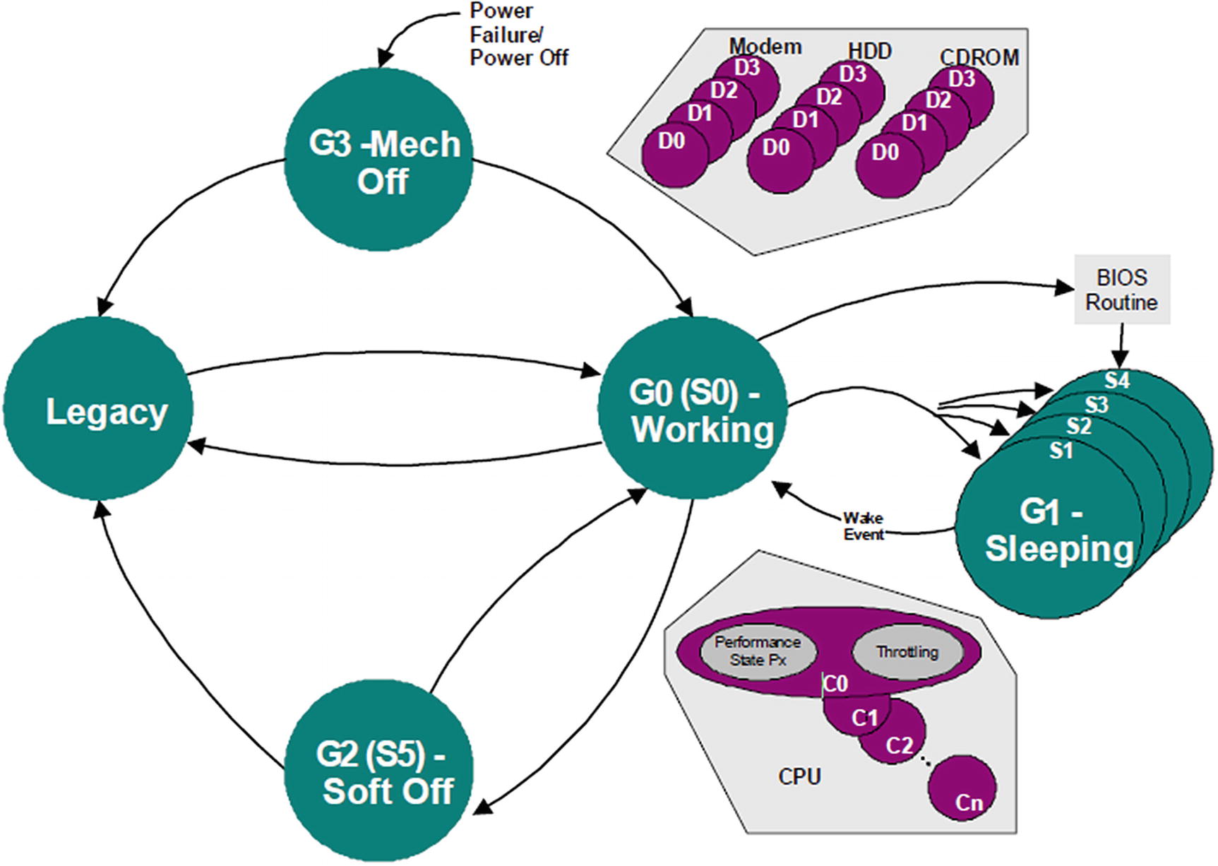
Global System Power States and Transitions (Source: ACPI Specification)
The system firmware is involved in the Sx suspend and resume. S1 resume is handled inside the OS directly. S4 resume and S5 resume are similar to a normal boot. S3 resume is a special boot path and has significant differences from the normal boot path. These differences create unique security challenges that we will focus on in this chapter.
Threat Model
S3 means “suspend to memory.” The OS context is in memory, and some firmware S3 context is also in memory. If malicious code can access the OS or firmware S3 context used in an S3 resume, it may impact the system’s confidentiality, integrity, and availability.
S3 Resume Asset
Asset | Integrity | Availability | Confidentiality |
|---|---|---|---|
Flash | Firmware code Firmware configuration | Firmware code Firmware configuration | N/A |
Memory | SMRAM | OS waking vector | SMRAM |
Silicon | Locked Register | Silicon register Memory configuration data | N/A |
TPM state | TPM2 platform hierarchy | TPM device state | N/A |
Storage disk | TCG storage BlockSID HDD Freeze | N/A | Disk password |
S3 Attack Surface
Attack Surface | Software Attack | Hardware Attack |
|---|---|---|
Flash access | Read/write configuration (variable) | Firmware code Firmware configuration |
Memory access | ACPI non-volatile storage (NVS) ACPI reserved memory | ACPI non-volatile storage (NVS) ACPI reserved memory |
Silicon register | Read/write silicon register (I/O, MMIO, PCI) | N/A |
TPM command | TPM device state (shutdown command) | N/A |
The attack may be performed during S3 suspend (such as modifying ACPI memory in the OS, sending malicious TPM command, or not sending a specific TPM command), in S3 state (such as updating the firmware code using a flash programmer), or during S3 resume (such as attaching a malicious PCI device for DMA access).
S3 Attack Mitigation
Asset | Prevention | Detection | Recovery |
|---|---|---|---|
Flash | Flash Device Lock. Variable Lock/Authentication. | Flash image verification in S3. Variable Check/RPMC. | Switch to normal boot for recovery. |
Memory | IOMMU in S3. Save data to LockBox(*). | Power loss detection. | Switch to normal boot. |
Silicon | Save configuration data to the LockBox(*). Register lock in the code. | N/A | N/A |
TPM state | Send TPM2_HierarchyChangeAuth(). | Check TPM2_Startup(). | Cap PCRs. |
Storage disk | Save configuration data to LockBox(*). | N/A | N/A |
LockBox
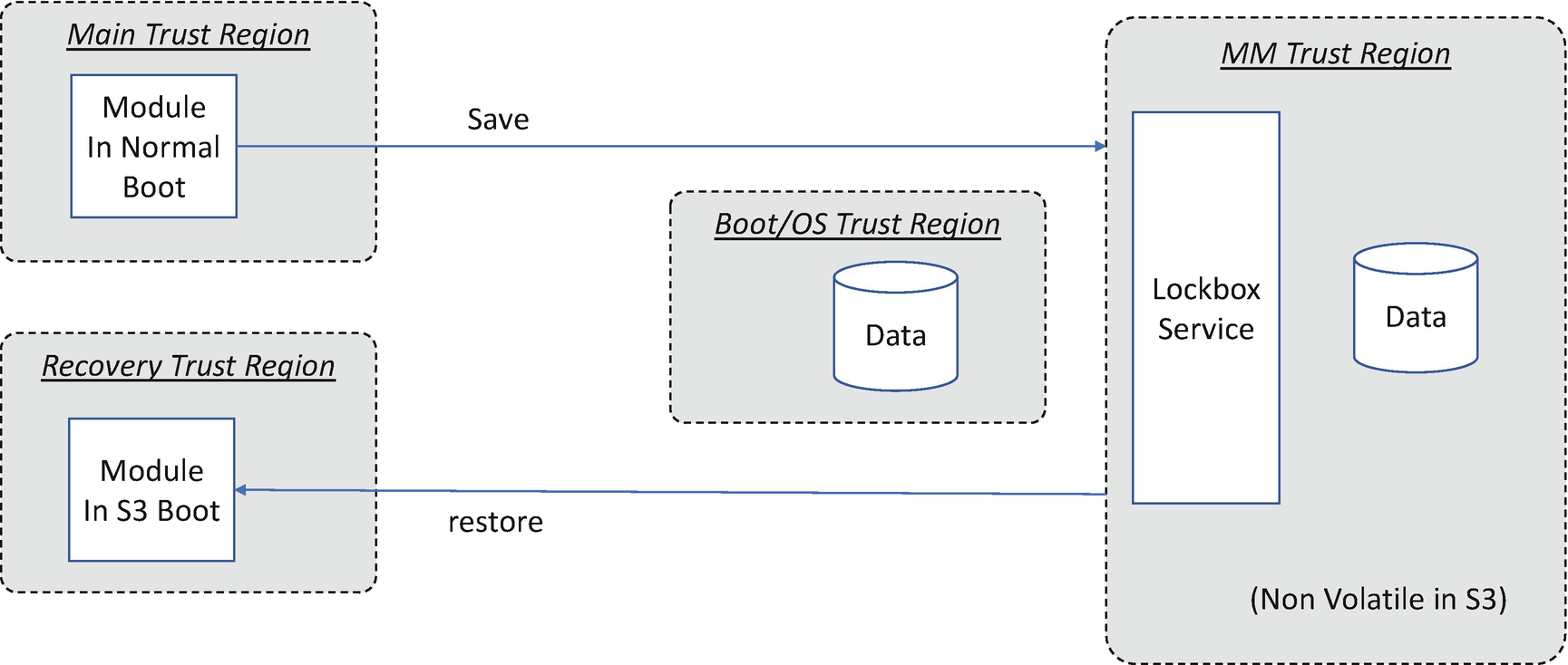
LockBox Usage in S3 Resume
The LockBox may provide confidentiality, integrity, and availability support. For confidentiality considerations, only an authorized entity can read the LockBox content. For integrity, only an authorized entity can write the LockBox content. For the availability concern, the LockBox should always be present. It is difficult to prevent hardware attacks because the hardware attack may include just removing power to destroy the contents of the memory or using a flash programmer to erase the contents of the flash.
S3 LockBox Implementation
Mechanism | Integrity | Availability | Confidentiality | Comment |
|---|---|---|---|---|
TEE (SMM) | Yes | Yes, for software attacks. No, for hardware attack. | Yes | Maybe unsupported before memory initialization. |
Variable | Requires Variable Lock or authentication. | Yes, for software attacks. No, for hardware attack. | Requires variable encryption. | Flash size limitation. |
TPM NV | Requires auth session or lock. | Yes | Requires auth session. | TPM device dependency, NV size limitation. |
Coprocessor | Yes | Yes | Yes | Coprocessor device dependency. |
Case Study
Now, let’s take a look at some real use cases for the LockBox implementation.
TEE-Based LockBox
PI Architecture S3 Resume Boot Path
In a normal boot, the PEI phase is responsible for initializing enough of the platform’s resources to enable the execution of the DXE phase, which is where the majority of platform configuration is performed by different DXE drivers.
The DXE phase hosts numerous services, which makes it rather large.
Loading DXE from flash is very time-consuming.
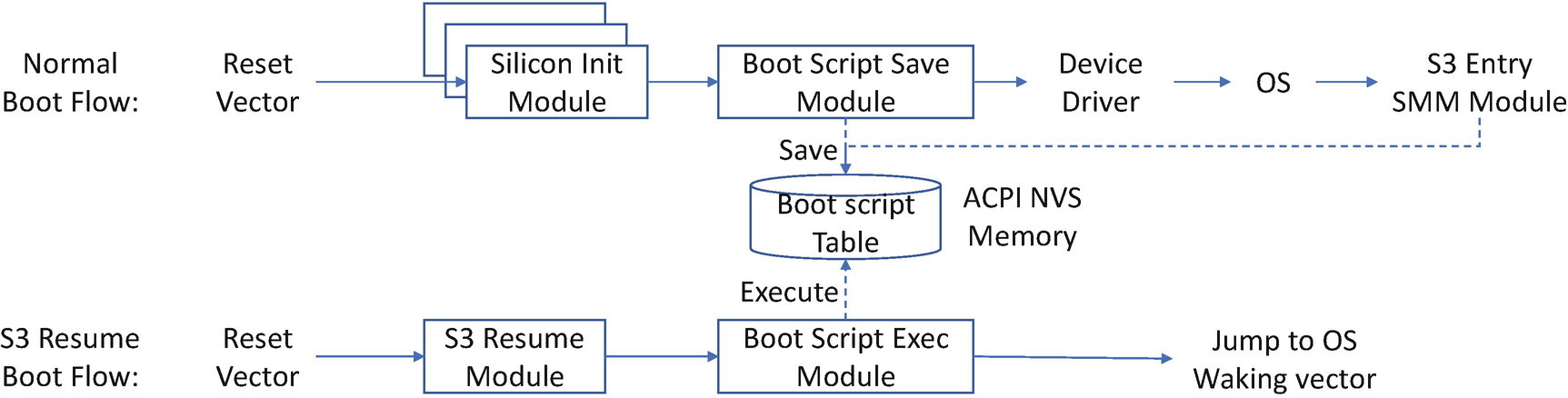
Instead, the PI Architecture provides a boot script that lets the S3 resume boot path avoid the DXE phase altogether, which helps to maximize S3 resume performance. The boot script is a set of entries such as IO_WRITE(Port, Data), MMIO_WRITE(Address, Data), and PCI_WRITE(Segment, Bus, Device, Function, Register, Data). It is a lightweight way to configure the silicon registers. During a normal boot, such as powering on from S5, DXE drivers record the platform’s configuration in the boot script, which is saved in NVS. During the S3 resume boot path, a boot script engine executes the script, thereby restoring the configuration.
The ACPI specification only requires the BIOS to restore chipset and processor configuration. The chipset configuration can be viewed as a series of memory, I/O, and PCI configuration operations which DXE drivers record in the PI Architecture boot script. During an S3 resume, a boot script engine executes the boot script to restore the chipset settings.
- 1)
In the DXE phase, the silicon/platform driver saves the register configuration to the boot script. This is the boot-time S3 script.
- 2)
In SMM, the silicon/platform driver can continue saving the register configuration to the table, even during OS runtime. A typical implementation is that when the OS triggers entry into S3, the system enters SMM. A special SMI handler collects the runtime silicon register settings such as PCI configuration and saves the information to the boot script. This is the runtime S3 script.
- 3)
In PEI, a boot script execution engine gets the boot script and replays the saved boot scripts to restore the system configuration. Both the boot-time S3 scripts and runtime S3 scripts are executed.
In practice, the boot script is large because it contains all of the silicon settings from the chipset as well as PCI express devices. Saving the boot script to a UEFI variable or TPM NV is not always practical because of limitations in the storage available in the TPM or in flash. Using the SMM environment is one architectural solution used by the EDK II BIOS to implement the SMM-based LockBox as the default one for boot script.
Besides the boot script usage, we also need to save the hard disk password to the LockBox to unlock the disk automatically. As such, the SMM-based LockBox needs to consider both integrity and confidentiality.
Before the SmmReadyToLock event, any driver can use the DXE LockBox or SMM LockBox interface to save information into the LockBox. Restoring information from the LockBox is also supported, although it is seldom used.
After the SmmReadyToLock event, the DXE code is no longer trusted. Attempts to save information into the LockBox by DXE code are rejected. The SMM code is already available, and the SMM code can use the SMM LockBox to save the runtime boot script.
During S3 resume, there is no need to save information to the LockBox. Therefore, the PEI LockBox does not provide the ability to save information into the LockBox.
With these rules, only the platform manufacturer’s code can save information into the LockBox. Third-party code cannot save information into the LockBox.
By default, the LockBox does not provide any confidentiality support. The DXE/PEI/SMM instances can restore the LockBox contents.
If a LockBox requires confidentiality, the creator needs to set the LOCK_BOX_ATTRIBUTE_RESTORE_IN_S3_ONLY attribute for the LockBox.
- If the LOCK_BOX_ATTRIBUTE_RESTORE_IN_S3_ONLY attribute is set, this LockBox can only be restored
Before the SmmReadyToLock event (or)
Between the time that the system enters S3 (S3Entry event) and the end of S3 resume (EndOfS3Resume event)
With this rule, secrets can only be restored before the platform exits the platform manufacturer’s authentication phase or during the firmware S3 resume phase. Third-party code cannot restore a secret from the LockBox.
- 1)
SaveLockBox(): Send data to the LockBox. A LockBox can be uniquely identified by a Globally Unique Identifier (GUID).
- 2)
UpdateLockBox(): Update data in the LockBox.
- 3)SetLockBoxAttributes(): Set LockBox attributes.
- a)
LOCK_BOX_ATTRIBUTE_RESTORE_IN_PLACE means this LockBox can be restored to its original address with RestoreAllLockBoxInPlace().
- b)
LOCK_BOX_ATTRIBUTE_RESTORE_IN_S3_ONLY means this LockBox can be restored in the S3 resume path only. This is used to provide confidentiality support.
- a)
- 4)
RestoreLockBox(): Get data from the LockBox to a caller-provided buffer address or the original buffer address.
- 5)
RestoreAllLockBoxInPlace(): Restore data from all LockBoxes which have the LOCK_BOX_ATTRIBUTE_RESTORE_IN_PLACE attribute.
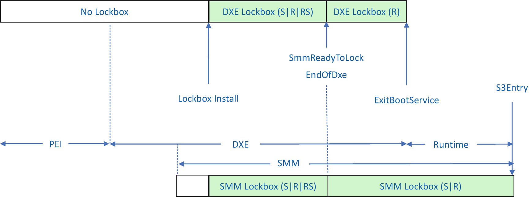
SMM-Based LockBox Features in Each Phase (Normal Boot)
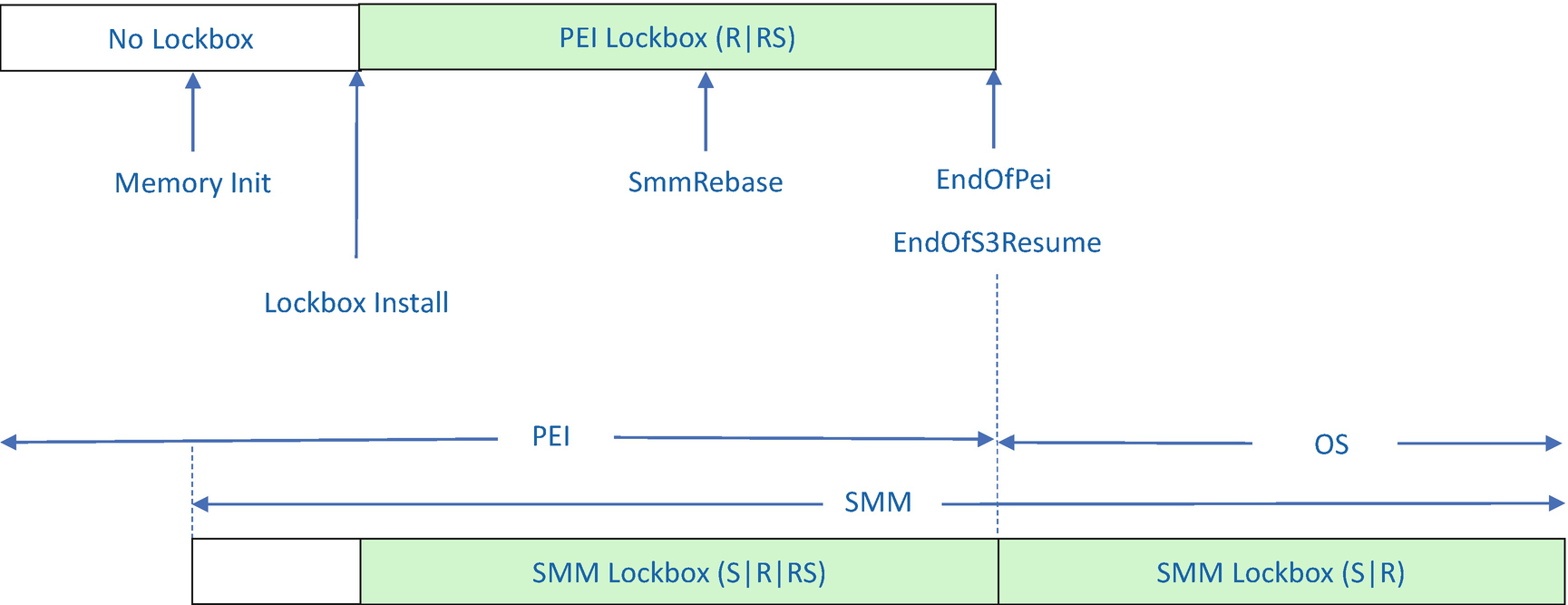
SMM-Based LockBox Features in Each Phase (S3)
S means LockBox Save.
R means LockBox Restore.
RS means LockBox Restore for the Secret.
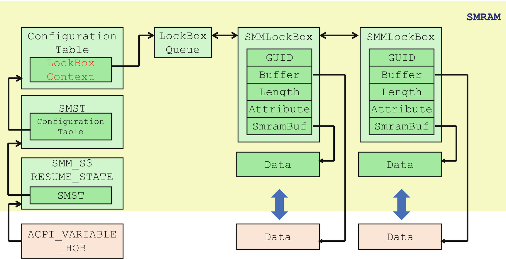
SMM-Based LockBox: Internal Data Structure
- 1)
GUID: Identifies the LockBox.
- 2)
Buffer: A pointer to the original data buffer. This is used when a caller requests to restore to the original buffer address.
- 3)
Length: The size of data in the LockBox.
- 4)
Attribute: The attributes of the LockBox.
- 5)
SmramBuffer: The data buffer in SMRAM.
The address of the LockBoxQueue is also saved as an SMM configuration table pointed to by the SMST. The reason is that if the SMI is not enabled yet, the PEI phase LockBox library can search the SMRAM region to get the LockBoxQueue and get all of the LockBox content. This makes the PEI LockBox service available before SMM is ready in the S3 resume phase.
The DXE phase LockBox library calls the SMM_COMMUNICATION protocol to communicate with the SMM LockBox service provider. The SmmLockBox driver provides the LockBox software SMI handler to service the request from the DXE instance.

SMM-Based LockBox: DXE/SMM Phase Usage
The DXE LockBox library supports five LockBox services before the SmmReadyToLock event. After the signaling of the SmmReadyToLock event, SaveLockBox(), UpdateLockBox(), and SetLockBoxAttribute() are closed and will reject further calls for security reasons. RestoreLockBox() can only restore the LockBoxes that do not have the LOCK_BOX_ATTRIBUTE_RESTORE_IN_S3_ONLY attribute. Otherwise, the call is also rejected.
The SMM LockBox library supports five LockBox services as well. It also records the current execution phase. After the SmmReadyToLock event, the firmware exits the platform manufacturer’s auth state. The LockBox save request from the DXE environment will be rejected after SmmReadyToLock. Before the system enters the S3, the platform signals the S3Entry event via the EFI_SMM_SX_DISPATCH2 protocol. Then the system goes into the S3 state. After the system wakes up, the PEI S3 resume drivers restore the environment. Before the firmware calls the OS waking vector, it signals an EndOfS3Resume event. The SMM LockBox only allows the LockBox secret restoration between the S3Entry event and EndOfS3Resume event.
- 1)
Using the SMM_COMMUNICATION PPI to communicate with the SmmLockBox service provider, similar to the behavior of the DXE LockBox library (see Figure 9-7).
- 2)
If the PEI LockBox library is used before SMM is ready, the SMM_COMMUNICATION PPI will return EFI_NOT_STARTED. In this case, the PEI LockBox library can search the SMRAM region directly to find the LockBox content. The LockBox internal data structure is shown in Figure 9-5. The PEI LockBox library can find the ACPI_VARIABLE_HOB to get the SMM_S3_RESUME_STATE location and then retrieve the SMM System Table (SMST) pointer. The address of the LockBoxQueue is saved as the SmmConfigurationTable entry in the SMM System Table (SMST). Care must be taken when PEI is 32 bits while SMM/DXE is 64 bits – all UINTN/VOID * defined in SMST must be parsed as UINT64 even in a 32-bit PEI execution environment.
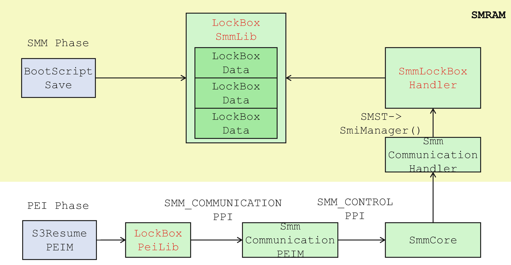
SMM-Based LockBox: PEI Phase Usage
The PEI LockBox library only supports two LockBox services in the S3 phase – RestoreLockBox() and RestoreAllLockBoxInPlace().
Secure Boot Script Implementation
- 1)
Boot script execution engine
The boot script engine executes the S3 boot script in S3 the resume phase.
The boot script engine may be in the TEE such as SMM. If so, there is no need to save it to the LockBox. Since SMM is a high-privilege environment, a platform might not want to give this level of privilege to the boot script engine.
Therefore, the current implementation lets the boot script be executed in the normal execution environment. During the normal boot, the boot script engine is loaded into the reserved memory. During S3 resume, the boot script engine executes from the reserved memory.
- 2)
Boot-time S3 script and runtime S3 script
Conceptually, a platform may have two boot scripts – a boot-time S3 script and a runtime S3 script. A boot-time S3 script includes the silicon settings recorded during the BIOS boot. The information must be collected before the EndOfDxe event. The runtime S3 script provides additional silicon configuration when the OS triggers the S3 suspend. A special SMI handler traps the S3 suspend action and saves the runtime silicon settings as additional data to the runtime S3 script.
The boot script driver implementation may choose to separate the two tables or combine them into one table. Both the boot-time S3 script and runtime S3 script are in ACPI non-volatile storage (NVS) memory and should be saved into the LockBox.
- 3)
S3 script metadata
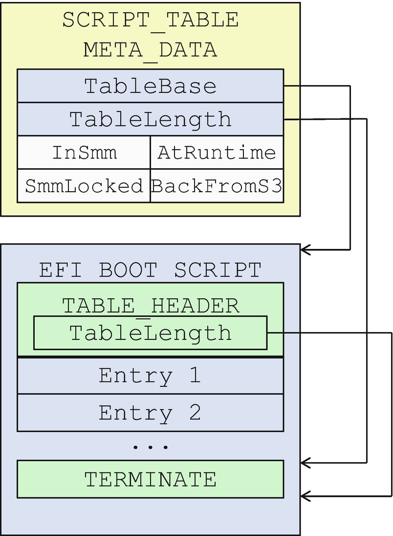
Boot Script and Metadata
- 4)
Special handling for DISPATCH OPCODE
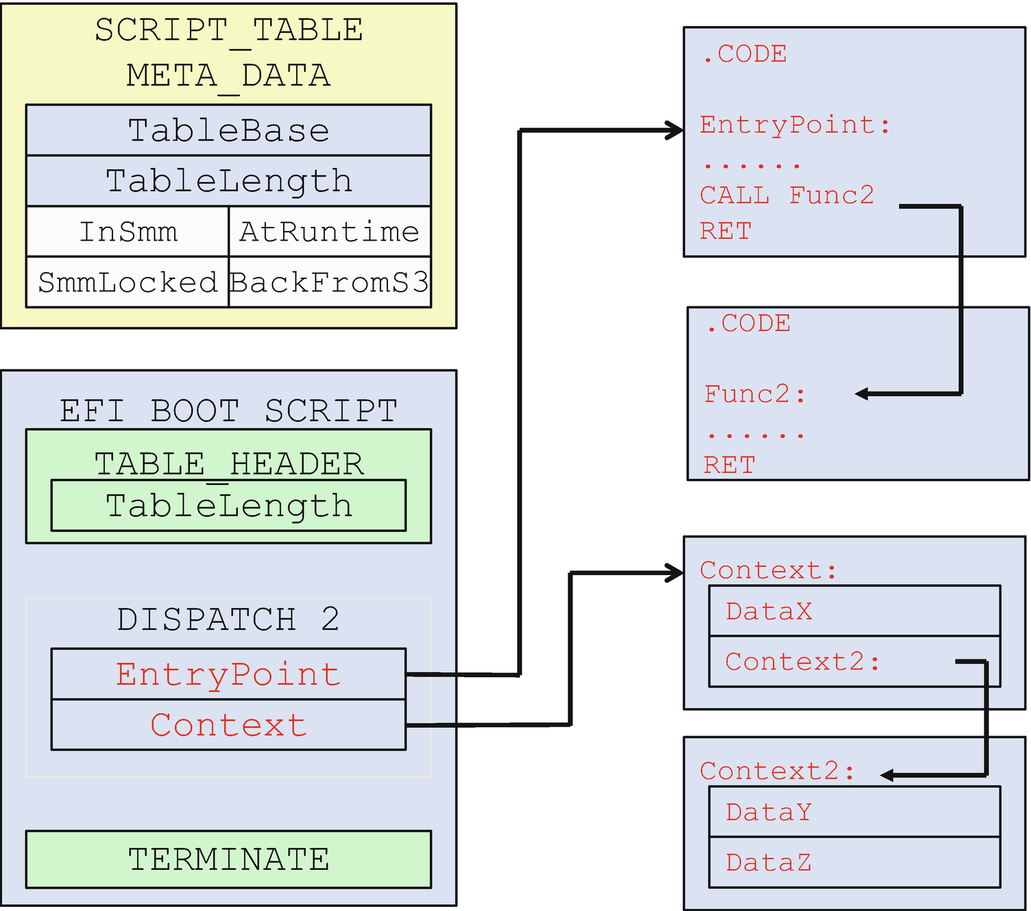
Boot Script: DISPATCH_2_OPCODE
The EntryPoint associated with the DISPATCH_2_OPCODE is an 8-byte address in the boot script. Saving the 8-byte EntryPoint in the LockBox cannot protect all of the code used by the EntryPoint function. Therefore, the driver that produces the 8-byte EntryPoint must use the LockBox services to protect the code used by the EntryPoint. If that function calls other functions, all code of the other functions must also be protected by the LockBox.
The Context associated with the DISPATCH_2_OPCODE is also an 8-byte address in the boot script. For the same reason, the driver that produces the 8-byte EntryPoint must use the LockBox services to protect the data referred to by the Context parameter. If the Context contains another data pointer, all the data referenced must also be protected by the LockBox.
This is described in more detail in the article “Implementing S3 Resume in EDK II” which describes the LockBox and S3 resume design in EDK II.
Variable-Based LockBox
The SMM-based LockBox can be used to protect data in most cases, but not in all cases. It depends on when the LockBox is ready. The SMM-based LockBox can only be consumed after the memory is initialized. If the S3 resume module needs to consume data before the memory is initialized, then we need to devise another solution. UEFI read-only variables are a good candidate because they are available before memory initialization. If the LockBox does not require confidentiality, the read-only variable can be used to store the data.
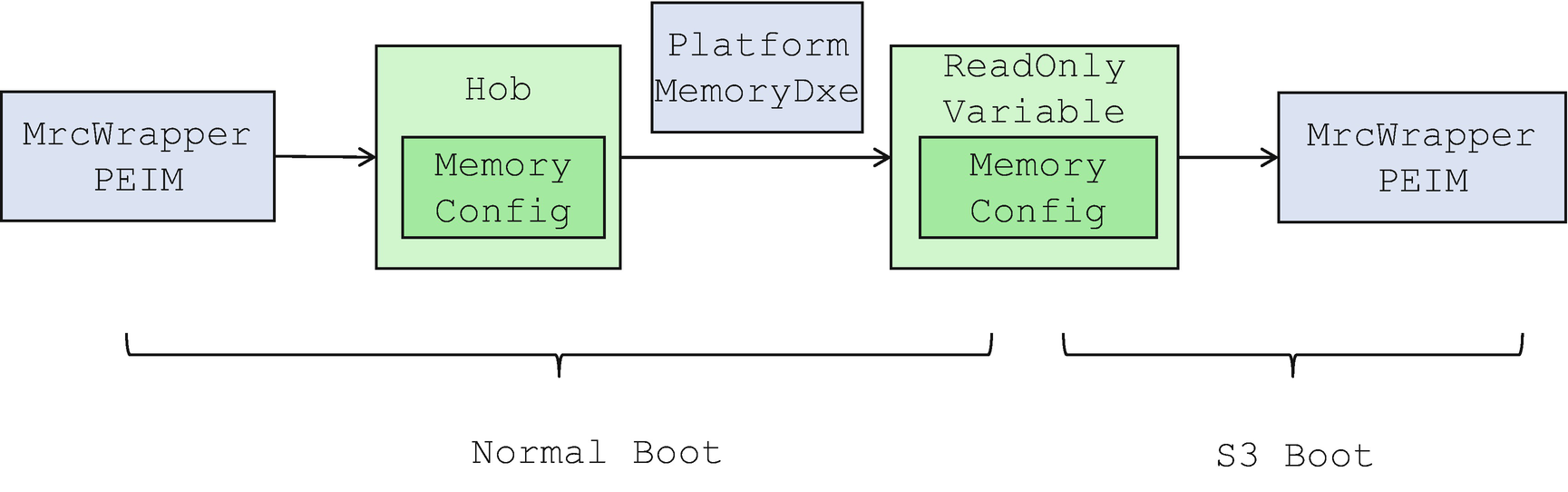
Read-Only Variable Usage for Memory Configuration Data
Coprocessor-Based LockBox
Besides a local TEE-based LockBox, a secure coprocessor such as an AMD Platform Secure Processor (PSP) may also help to save and restore the silicon configuration.
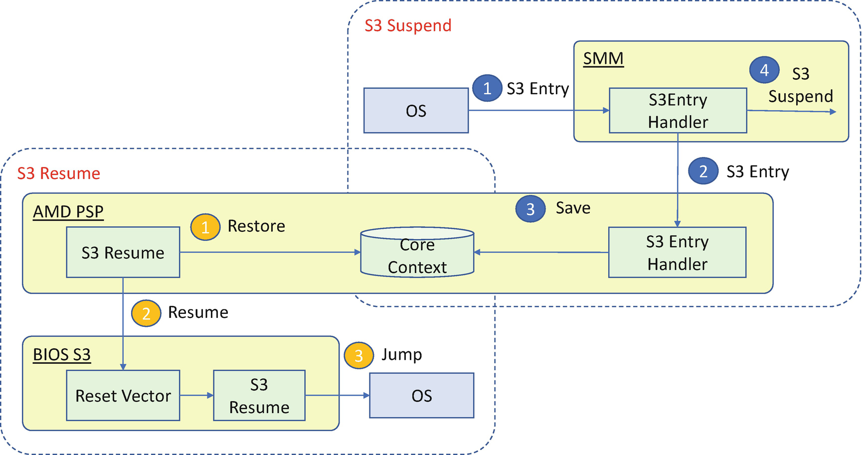
AMD PSP–Assisted S3 Resume
Attack and Mitigation
Now, let’s take a look at some real cases for the LockBox attack and mitigation.
Missing LockBox Protection
Some firmware implementations include the register lock in the S3 boot script. If the script is not protected, the attacker may modify the boot script to inject some malicious opcode or remove the lock register access in the S3 resume. The boot script must be saved into the LockBox.
Besides the boot script, if the firmware uses the DISPATCH OPCODE, the firmware should also save the image that produces the DISPATCH EntryPoint to the LockBox and save the context data to the LockBox. Otherwise, the attacker can modify the DISPATCH function to inject malicious code.
Incorrect LockBox Attribute
The LockBox should also be used to save secrets used during S3 resume, such as hard disk storage passwords. For secrets like these, the LockBox must use the LOCK_BOX_ATTRIBUTE_RESTORE_IN_S3_ONLY attribute. Otherwise, the attacker may dump the LockBox content during normal boot.
Missing Register Lock
During normal boot, some silicon registers are locked to maintain the system integrity such as SMRAM lock and flash lock. The same registers must be locked during S3 resume as well. Otherwise, the attacker can trigger a S3 resume to put the system into an unsafe state.
A platform may use the PEI S3 resume code to lock the registers or put the lock action in the boot script. Using the code in the flash to lock the register is highly recommended because it does not depend on boot script protection.
Summary
In this chapter, we discussed the S3 resume path and focused on LockBox design. In the next chapter, we will discuss access control in the firmware.
References
Conference, Journal, and Paper
[P-1] Jiewen Yao, Vincent Zimmer, “A Tour Beyond BIOS Implementing S3 Resume with EDK II,” Intel Whitepaper 2015, https://github.com/tianocore-docs/Docs/raw/master/White_Papers/A_Tour_Beyond_BIOS_Implementing_S3_resume_with_EDKII_V2.pdf
[P-2] Roger Lai, “AMD Secure and Server Innovation,” in UEFI Plugfest 2013, available at www.uefi.org/sites/default/files/resources/UEFI_PlugFest_AMD_Security_and_Server_innovation_AMD_March_2013.pdf
[P-3] Rafal Wojtczuk, Corey Kallenberg, “Attacks on UEFI Security,” in CanSecWest 2015, available at https://cansecwest.com/slides/2015/AttacksOnUEFI_Rafal.pptx
[P-4] Oleksandr Bazhaniuk, Yuriy Bulygin, Andrew Furtak, Mikhail Gorobets, John Loucaides, Alex Matrosov, Mickey Shkatov, “Attacking and Defending BIOS in 2015,” in RECon 2015, available at www.c7zero.info/stuff/AttackingAndDefendingBIOS-RECon2015.pdf
[P-5] Yuriy Bulygin, Mikhail Gorobets, Oleksandr Bazhaniuk, Andrew Furtak, “FRACTURED BACKBONE: BREAKING MODERN OS DEFENSES WITH FIRMWARE ATTACKS,” in BlackHat US 2017, www.blackhat.com/docs/us-17/wednesday/us-17-Bulygin-Fractured-Backbone-Breaking-Modern-OS-Defenses-With-Firmware-Attacks.pdf
Specification and Guideline
[S-1] UEFI Organization, “ACPI Specification,” 2019, available at www.uefi.org/
[S-2] UEFI Organization, “UEFI Platform Initialization Specification,” 2019, available at www.uefi.org/