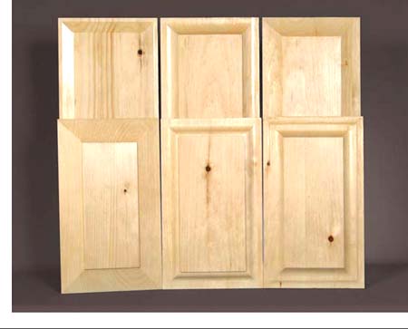
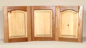
As most cabinetry is for storage, doors to hide the spaces and drawers to ease in access are important parts of an attractive and functional storage cabinet. There are a variety of styles available and I have tried to show most of the major options available here.
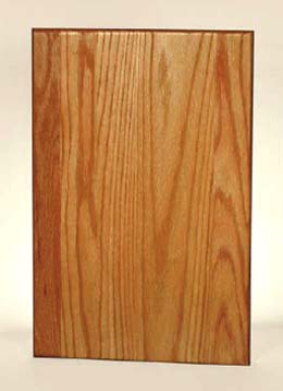
Slab or flat panel doors are the simplest form of cabinet doors. In most cases, they are made using sheet materials such as veneer plywood or particleboard (PB), melamine PB, medium-density fiberboard (MDF), or solid-wood glued-up panels.
These flat panels can be edge-taped with a matching material, solid-wood edged, or formed when the edges are solid material. Because these doors are flat, mouldings can be applied to create visual interest or a pattern can be routed into the face. In many cases, slab doors made with materials like MDF can be painted.
They are relatively inexpensive because a 4′ × 8′ sheet will yield quite a few doors. However, because they are flat they can look plain but we can add some interesting details with mouldings and decorative scroll pieces. Designs can be cut into the face of solid-wood panels and MDF sheet stock using the pattern-routing jig described at the end of this chapter.
There are dozens of ways to make panel doors and just as many ways to add detailing. I’ll show you a few in this chapter with some of the sheet stock material that’s available. Doors are the most expensive part of any cabinet project, so using sheet material is one way to keep the cost at a reasonable level. And with a little imagination—using paint, designs, mouldings and routing techniques—slab doors can add a great deal to the overall look of your cabinet project.

Melamine PB doors are typically flat doors cut from a sheet of 4′ × 8′,  -or ¾″-thick melamine particleboard. They are low-cost doors because a sheet will yield quite a few doors at about $1 per square foot. The edges are finished with iron-on tape that is available in many colors to match the sheet stock. White melamine PB is the most common sheet material on the market.
These doors have many uses, such as for workshop and laundry room cabinets or for basic storage cabinetry in your home. The colored sheets can be used to create work and storage cabinets for children’s rooms or in a basement playroom.

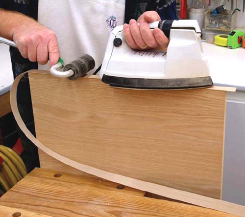
1 Cut the melamine sheet material to the door size required and apply tape to all exposed edges. The most common edge tape available has an adhesive back, which is activated with an iron. Be sure to roll the tape when the glue is hot to achieve full edge contact.

2 Trim the edge tape to the board thickness with a two-sided edge trimmer, sharp chisel or knife.
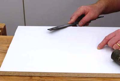
3 Dress the edges with a laminate file, removing any portion of the tape that extends past the board’s face. A smooth surface between edge tape and door face will help prevent damage to the tape.
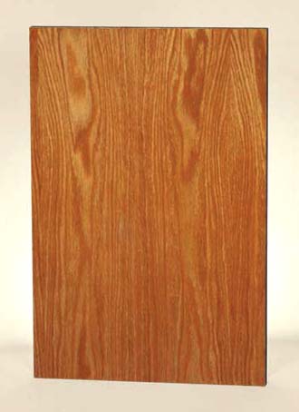
Veneer-slab doors can be made using veneer-covered particleboard or plywood sheet material. The construction steps used to build this type of flat panel door are much the same as for melamine PB doors. Wood-veneer tape, which matches the face veneer, is used to dress the panel edges. However, there are special cutting techniques that must be used when edge-dressing the tape.
1 Apply the wood-veneer edge tape using an iron to activate the adhesive. Roll the tape as it’s heated to ensure a good bond between the tape and board edges.
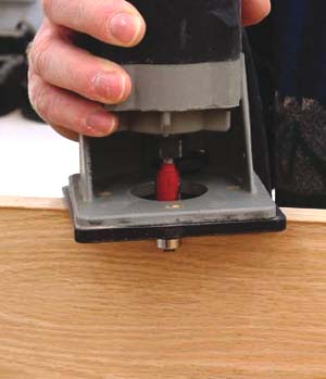
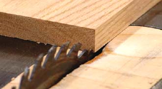
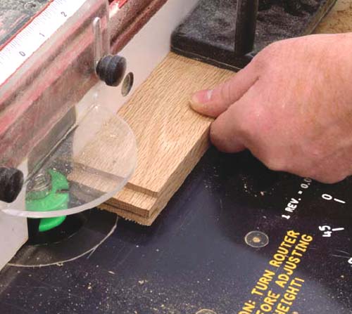
2 Wood-veneer edge tape is real wood as the name suggests. It has a wood species — oak, for example — and a grain structure that tends to split along the grain line when trimmed with a knife. Using a router and flush-trim router bit with a guide bearing helps to ensure a clean cut without splitting the veneer.

3 Light passes with fine sandpaper can be used to smooth the tape edges. The edge between the tape and the board face, should be smooth to lessen the chance of tape damage.

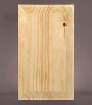
Solid wood can be used to dress the edges of veneer-slab doors. It’s a tougher edge treatment that opens up a few options not available with edge-taped doors. The solidwood edge can be machined with a router using a roundover or chamfer bit to add a little more detail to these flat doors.

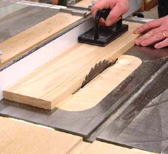
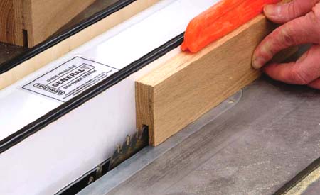
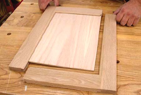
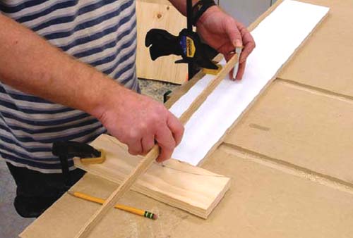
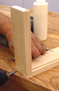
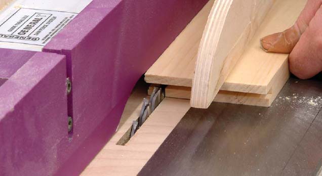
1 Cut the slab door to the required size less ½″ on the width and length. Rip ¼″-thick solid-wood strips on the table saw and attach them to the door slab. Use glue and small brad nails to secure the wood strips. The first two strips are attached on opposite edges, aligning one end of each strip flush with the board end. Notice that I’ve cut the wood strips longer than the door length.
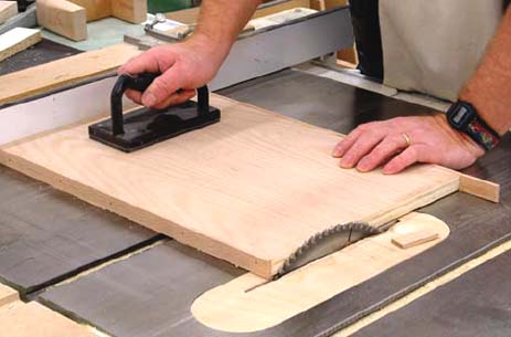
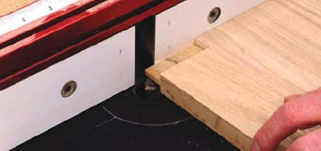
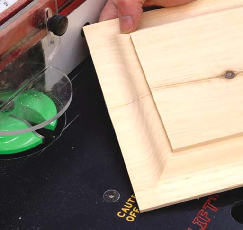
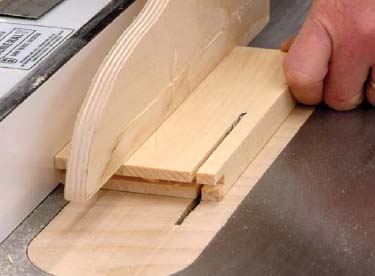
2 Set the table-saw fence to the panel length and trim the long ends of the wood strips. The strips will be perfectly flush with the panel ends.
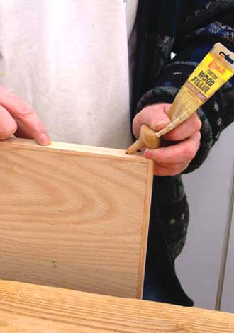
3 Follow the same procedures, as detailed in step two, for the remaining two strips. Install and trim to length on the table saw. Use colored wood filler that matches the final door finish to fill the nail holes. Sand the wood edges smooth.
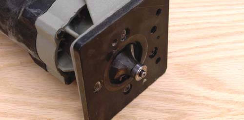
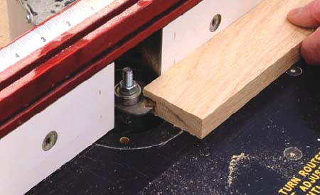
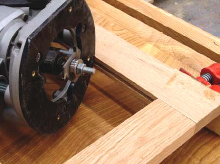
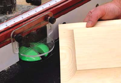
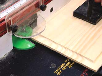
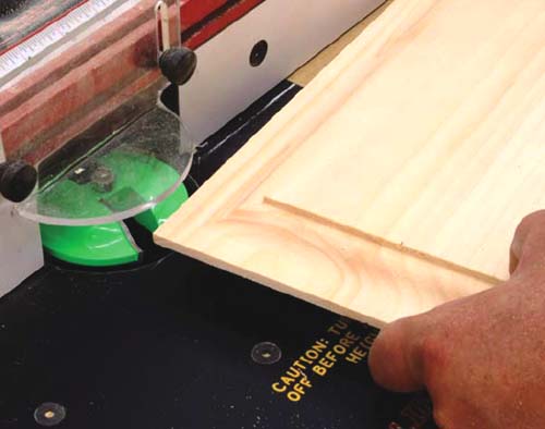
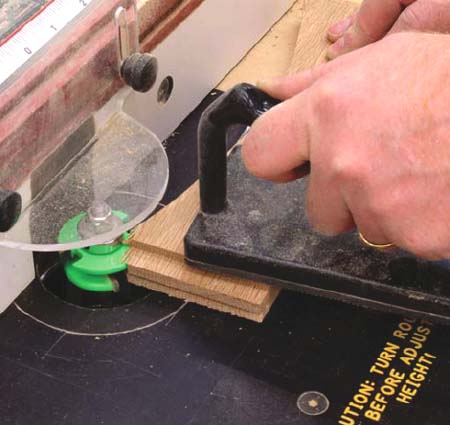
4 The solid-wood edges can be machined with a router. A roundover bit (shown in the photograph) or a chamfer bit are two common edge treatments for these doors, but there are many styles of bits that may be used.
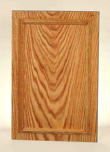
Veneer-core slab doors with taped or wood edges can be “dressed” up by adding mouldings. These are available at lumber yards and woodworking stores. There are dozens of patterns and styles that can be attached to the door
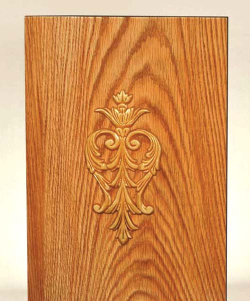
You can also buy intricate scrollwork patterns in wood that can be attached to slab doors. The same process applies; a little glue and a couple of brad nails are all that’s needed. Or, if you have a scroll saw, you can make your own unique door-trim mouldings.
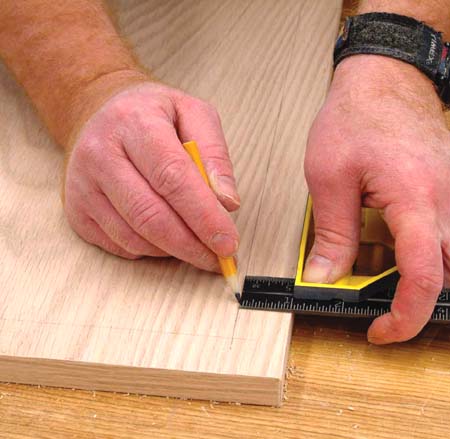
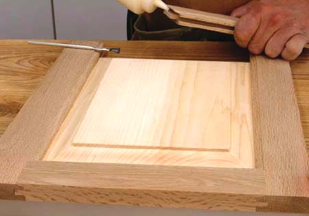
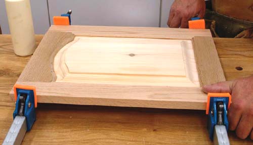
1 When applying mouldings to slab doors, the first step is to accurately mark the moulding position on your doors. This is important for achieveing a balanced-looking door.
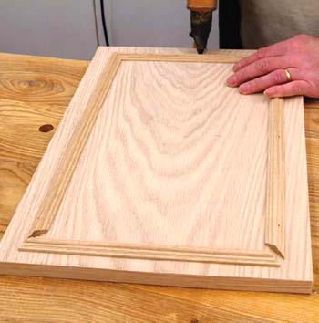
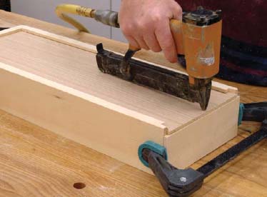
2 Wood moulding can be attached to veneer doors using a little glue and small brad nails. Some mouldings are delicate, so they must be handled carefully.
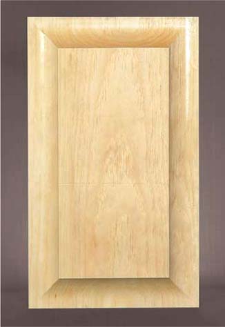
Solid-wood doors can be a nice addition to any cabinet project. Because they are solid, these slab doors can be machined using many more techniques than is possible with melamine or veneer-covered slab doors.
The process used to make solid-wood doors starts with the glue-up process of narrow boards to form a large panel. The edges of the narrow boards are machined straight and flat so all boards fit tight to each other. Usually a jointer is used to dress the boards, but a table saw may be used by following a few simple steps.
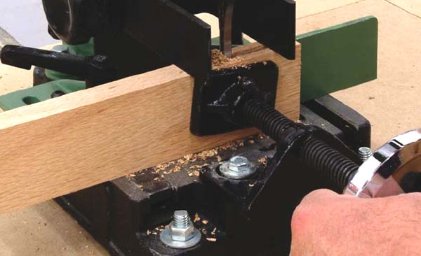
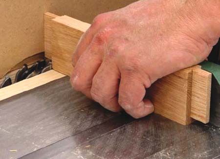
1 Edge-dressing narrow boards for solid-wood glued-up panels can be done on a well-tuned table saw. First, be sure the fence will tightly lock into place and is running parallel to the saw blade. The blade rotation must be smooth, without end play, to get the straight cuts on each board that are needed for successful glue ups. Rip one edge of the board; then turn it around, keeping the same face up, and rip the other edge. Both edges should be parallel to each other and at 90° to the board’s face.
2 Remove small portions of the board’s edge during each cut. Make sure that the edges are parallel with the board’s face.
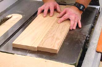
3 Test the boards by pushing them together on a flat surface. They should butt tightly to each other without a great deal of pressure. If necessary, repeat the edge-ripping steps until the boards fit together properly.
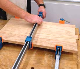
4 Apply glue to all the edges that are to be joined. Use clamps, alternating on the top and bottom, to bring the boards together. Don’t apply too much clamp pressure or you will squeeze out all the glue and your joints will fail.
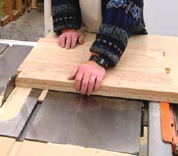
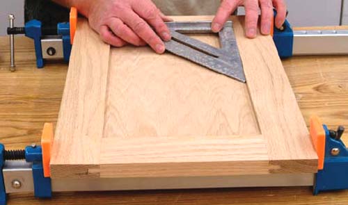
5 Use a panel crosscutting jig to square the ends and trim the door to its proper length. Then, rip the width to the correct size.
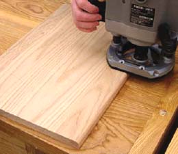
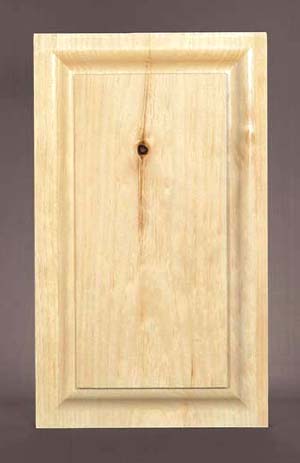
6 The edges can be machined with any bit profile, including a roundover in a router, as shown. You can also use profile bits such as a cove, ogee or chamfer to add visual interest to the door.
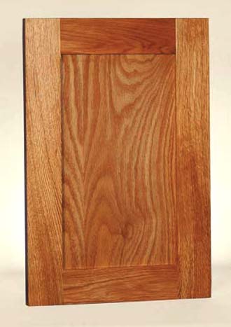
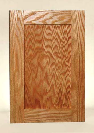
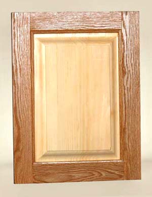
Traditional frame and panel doors (whether built with a flat or raised panel) are essentially built the same way, using five parts. Two vertical members of the door called stiles, two horizontal members called rails, and a center panel. With a flat-panel door, the center panel is usually veneer core plywood (no worries about wood movement), while a raised center panel will be solid wood.

As the construction is very similar, we’ll start with the flat panel first, then follow with the raised panel.
The term “flat panel” refers to the plywood veneer center panel. The center panel of these doors isn’t always ¼″ thick plywood veneer. The two stiles and two rails are often joined in the same manner with sheet glass or decorative leaded glass center panels.
Corner joinery, or attaching the stiles to the rails, is the main concern with five piece doors. There are a number of methods using a table saw, router table, and mortising machine that can be used to form the joints. The steps are simple and straightforward but good woodworking practices must be used to produce solid frames.
This chapter will also deal with doors that have an arch or cathedral style cut on the top, bottom, or both rails. Making this style of door is a little more challenging but the procedures can be successfully mastered using simple geometry.
The rail width equals the door width minus the stile widths. However, you also have to account for the tenon lengths on each end of the rail. A 12″-wide door with 2¼″-wide stiles requires a 7½″-wide rail, but you also need an additional 1½″ for the tenons. The rough rail length before tenons are cut is therefore 9″. With the ¾″-long tenons, ¾″-deep grooves and 2¼″-wide stiles, the rough rail length will always be 3″ less than the door width. For example, using the same part dimensions, a 19″-wide door requires a 16″ rail before tenons are cut — it’s that easy when using the above combination of door-part dimensions. Center panel dimensions are easily calculated as well. The sample setup means the ¼″ plywood panels will be 3″ less than the overall door width and height. Therefore, the panel for a 12″-wide × 18″-high door will be 9″ wide × 15″ high.

This style of door is made using a table saw only. The project door will be 12″ wide by 18″ high. The stiles and rails are solid 2¼″-wide solid wood, which are ¾″ thick. The center panel is ¼″-thick veneer-covered plywood.
1 Cut the stiles and rails to the proper length. I normally use ¾″-thick × 2¼″-wide stock for my door frames. The rail tenons are ¾″ long to match the grooves in the stiles. This combination of rail and stile width along with tenon length and groove depth makes it easy to calculate door-part dimensions. Each rail and stile needs a ¼″-wide groove that’s ¾″ deep, centered on one long edge. Cut the groove with a standard blade in two passes. Reverse the feed direction on the second pass to center the groove. Or, you can use a stacked dado blade set to cut a ¼″-wide slot centered on the edge of each part.

2 The tenons on both ends of the two rails are ¼″ thick × ¾ long. They should be centered on the rail ends to fit the stile grooves. Tenons can be cut using a standard table-saw blade or a stacked dado blade. Cut a sample tenon and test-fit the assembly before forming the tenons on the actual rails.

3 The center panel is ¼″ thick veneer plywood to match the rails and stiles. I’m using solid-oak wood and veneer plywood, but any species of wood may be used. The center panel is 3″ less in width and height. My 12″-wide × 18″-high door requires a panel that’s 9″ wide × 15″ high. However, I usually cut the center panel less in width and height to allow for wood movement. Cut the panel to size and test-fit the door parts.
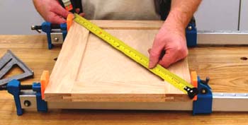
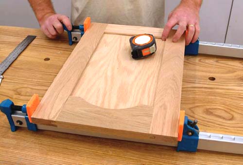
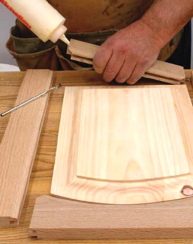
4 Assemble the door with glue on the rail tenons only. The center panel isn’t normally glued in place, but left to float. Clamp the door, then measure the diagonals. If both measurements are the same, the door is square. If there is a difference, lightly tap the long measurement diagonal to equalize the dimensions before the adhesive sets up.
1 These doors are made following the same procedures that I detailed for the table saw. However, my slot cutter can only cut a groove that’s ½″ deep so the tenon dimensions will be reduced to ½″ in length. If you have a wing or slot cutter that cuts at ¾″ deep, use that length of tenon. Cut the rails and stiles to length, then rout a ¼″-wide × ½″-deep groove along one edge of each part. Be sure to center the grooves on the rails and stiles. My slot cutter will only cut a  -wide groove, but I want a ¼″ groove. If you have a tool that won’t cut the full width, set the bottom edge of the cutter ¼″ about the router table surface. Make the first cutting pass, then flip the wood and make a final pass. The groove will be ¼″ wide and centered when using ¾-thick stock.
2 Replace the slot bit with a ½″ router bit to cut the rail tenons on each end. Once again, use a test piece of wood to center the tenon and verify its proper thickness. The tenons should fit snugly into the rail grooves without distorting the sides of those grooves. A loose fit will result in the joint failing, while a tight fit will put stress on the groove walls and may split the stile.
3 Cut the ¼″-thick center panel to the correct size and test-fit the door assembly. Once you are satisfied with the fit, apply glue to the tenons, install the center panel, and clamp until the adhesive sets up. Remember, the panel’s width and height should be  greater than the inside dimension of the door frame because the grooves are ½″ deep in my case. The panel should have a little space to allow for wood movement of the stiles and rails.
There are many edge options that you can use to add visual interest to your doors. Most are easily formed with router bits, including the cove, roundover and ogee. However, there are dozens more profiles, so experiment with a few until you find one that suits your taste. A word of caution when adding profiles, the combination of door profile and hinge style may present a problem (European hinges rest in holes that are about ½″ deep and  away from the door’s edge, while traditional hinges, such as butt or piano hinges, require a full-thickness edge to be properly installed). So Always test a profile cut on scrap lumber, then mount a sample hinge to determine if there will be proper clearance and sufficient material left for the hinge hole.

Door frames can be built using mortise-and-tenon joinery. Tenons are cut on the ends of each rail and a mortise is formed in the stiles. This is a traditional joinery option that is still widely used.
The tenons may be cut by hand, on the table saw or on a router table, and the mortises formed with a drill press and chisel. I will be using a dedicated mortiser to cut my tenons because that’s the method I prefer. If you use mortise-and-tenon joinery a lot, a dedicated mortiser would be a good investment.
1 Cut the two stiles and rails to size to build a 12″-wide × 18″-high door. The stiles should be 18″ high and the rails 9″ wide when you’re using 2¼″ wide stiles and rails with ¾″-long tenons. The stiles need a ¾″ deep mortise that’s 1¾″ long in the center at each end. Start all the mortises ½″ from each stile end. As mentioned, if you don’t own a dedicated mortiser, drill a series of holes and clean out the waste with a sharp chisel to square the holes.
2 Form a ¾″-long × ¼″-thick tenon in the center of each rail end. The top outside ½″ of the tenons are notched so they will fit in the stile mortises that begin ½″ from each stile end. The tenons can be notched after they are cut to size with the same saw setup.
3 If you plan on cutting rabbets on the back face for a glass panel, brush glue on the tenons, then assemble the door. The door frame’s back face needs a rabbet cut to hold the center panel. Glass, veneer plywood, or any type of decorative panel may be used. The rabbet is cut with a router bit called a slot cutter. It’s equipped with a guide bearing that will follow the inside perimeter of the frame. You may need to make a number of passes with the slot cutter to achieve the desired rabbet depth. That depth will depend on the thickness of material used for the center panel. If you want a centered wood panel, use the same slot bit to cut the grooves. As stated before, my slot cutter is only thick, so I have to make two passes. Moreover, it only grooves ½″ deep, so my center panel for this 12″-wide × 18″-high door will be 8 wide × 14 high, which leaves a little space for wood movement. Once the cuts for the panel you want to install are completed, glue and clamp the frame.
Cutting curves, arcs and other radius patterns in rails is a little more difficult than cutting a straight-rail door. There are patterns for arched doors that can be purchased at woodworking stores. However, a little bit of simple geometry and an understanding of how the arc is varied based on door width will allow you to make your own patterns.
The arched door has a curve cut into the top rail and is referred to as an arched frame-and-panel door. I’ll explain how the top rail can be cut to form a cathedral-style door later in this chapter. The important issue to remember is that kitchen doors vary in width. The challenge is to maintain a visually consistent appearance among all the doors in the room, no matter what width. To accomplish this, all curves in each door must follow certain rules. I’m using 3¼″-wide upper curved rails for this example.
The straight stiles and bottom rail are 2¼″ wide in my design. So, to maintain a consistent appearance between a door that’s 12″ wide and one that is 24″ wide, I need a constant reference point on both doors. I can achieve a consistent look among all my doors by making sure my arc is 2¼″ down from the top center of all the curved rails — no matter the door width. All my doors will have the same measurement above the arc and only the radius of the arc will change.
The drawing illustrates the differences between rails for a 12″-wide door and a 24″-wide door. Only the rail width and arc radius change; all other values remain the same. The start and end of each arc is at the point where the rail meets the stiles. In addition, there should always be 2¼″ of solid wood above the center of each arc.
Starting and ending the arc at the same place on doors of different widths, as well as maintaining the 2¼″ measurement above the arc, will make all the doors appear similar. Changing those fixed points as the width changes would dramatically change the door’s appearance. You can verify these design principles by measuring different arched doors of different widths in any typical kitchen.
For detailed calculations on how to determine the radius of an arc for any door, refer to page 131.
UPPER CURVED ARCH RAIL
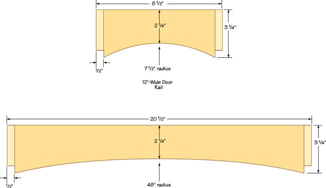


1 This example door is 12″ wide and 18″ high. I’m using ¾″-thick stock for the stiles and rails with a ¼″-thick veneer plywood panel. All stock used for the doors is ¾″ thick. Cut two stiles at 2¼″ wide × 18″ long and one upper rail at 3¼″ high × 8½″ wide. The bottom rail is 2¼″ high × 8½″ wide. Note that the width of the upper and lower rails includes a ½″ long tenon on each end. Cut the tenons on both rails. All the tenons are ¼″ thick × ½″ long and are centered on the rail ends. A stacked dado head cutter on your table saw is the best tool to form these tenons.

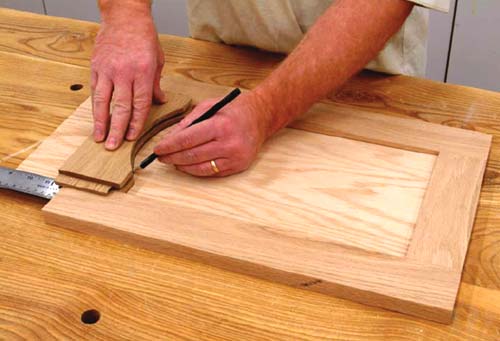
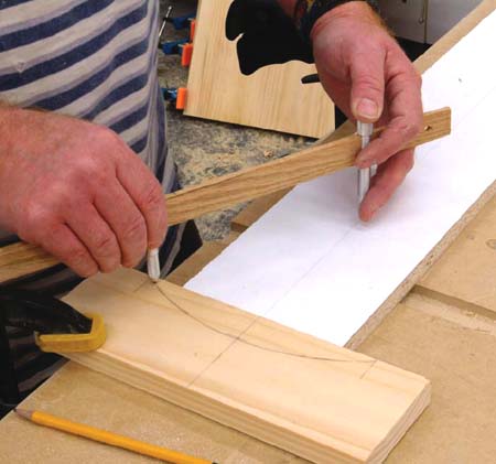
2 Draw an arc on the wider upper rail, beginning and ending at each end and leaving 2¼″ of wood above the arc at the center of the rail. I use an adjustable “yardstick” compass that’s available at most woodworking stores. The arc will have a radius that is determined by the rail width (see page 131).
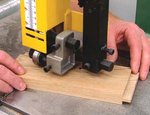
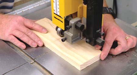
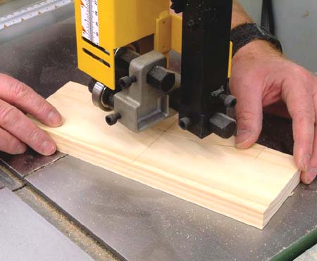
3 Cut the arc in the top rail using a band saw or jig saw. Leave the line visible when you cut and smooth the curve with a drum sander.
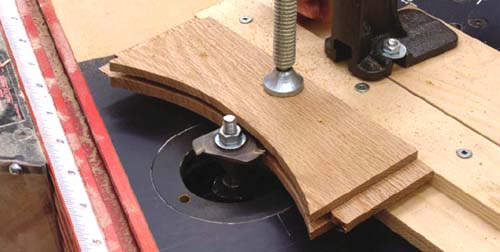
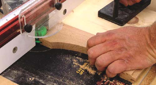
4 The grooves on the stiles and bottom straight rail should be ½″ deep and ¼″ wide. To cut the groove in the arched top rail I’ve used a wing or slot cutter in my router table. Door-frame parts are safely held, and routered, in my shop-made jig, detailed below. If your cutter is like mine, you’ll need to flip the rail to get a ¼″-wide groove that will be ½″ deep. The other parts grooved on the table saw are ½″ deep as well.

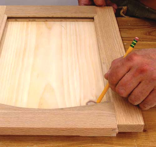
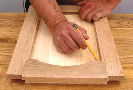
5 The  plywood center panel should be cut before beginning the door assembly. The simplest method of determining the correct arc for the center panel is to dry fit the door frame with the panel in the stiles and lower rail. I’ve left the panel long on top. Lightly trace the inside profile of your upper rail on the panel with the rail held
  above the top edges of the stiles. Use a band saw or jig saw to cut the arc in the panel.

6 Dry fit the door assembly. Once all the parts fit properly without any undue force required, apply glue to the mortise and tenons. Clamp the door assembly and make sure that the door is square before the adhesive sets.
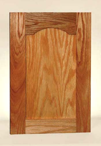
The cathedral-style frame-and-panel door is a variation on the arched frame and panel. All the construction steps are identical except the design of the curved rail(s).
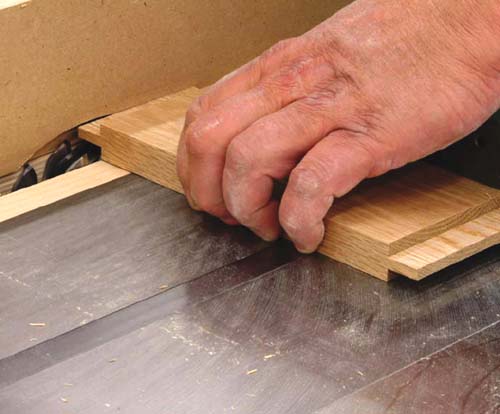
Prepare the stock as for the arched door style and cut the upper rail as shown in the drawing. The rail tenons are cut before the curve, so the flat edges on both sides of the rail can be used to guide the stock on the table saw.
CATHEDRAL FRAME & PANEL
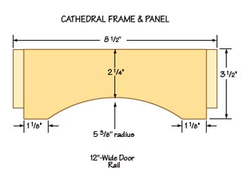
In this design, dimension A, which is the width of the straight run at the ends of the rail, is one-half the stile width. The material above the arc, dimension B, on the rail equals the stile width. The arc radius can be changed by altering the width of A, but keep B equal to the stile width and the door will look balanced.
Maintaining A at half the stile width and B equal to the stile width means that the radius of the arc changes for different door widths. However, all doors used for the same project, such as a cabinet doors for a kitchen, will look consistent if dimensions A and B are identical on all the doors.
1 This example door is 12″ wide × 18″ high. I’m using ¾″-thick stock for the stiles and rails with a ¼″-thick veneer plywood panel. All stock used for the doors is ¾″ thick. Cut two stiles at 2¼″ wide × 18″ long and one upper rail at 3¼″ high × 8½″ wide. The bottom rail is 2¼″ high × 8½″ wide. Note the width of the upper and lower rails include a ½″-long tenon on each end. Form the tenons on both rails using a stacked dado blade on the table saw. All the tenons are ¼″ thick × ½″ long and centered on the rail ends.

2 Draw an arc on the wider upper rail but remember to begin and end the radius 1 short of each end as shown on the drawing. The arc will have a radius that is determined by the rail width (see page 131).

3 Cut the arc in the top rail using a band saw or jig saw. Leave the line visible when you cut and smooth the curve with a drum sander.
4 The grooves on the stiles and bottom straight rail should be ½″-deep × ¼″-wide. To cut the groove in the arched top rail I’ve used a wing or slot cutter in my router table. Door-frame parts are safely held, and routered, in my shop-made jig, detailed below. If your cutter is like mine, you’ll need to flip the rail to get a ¼″-wide groove that will be ½″ deep. The other parts grooved on the table saw are ½″ deep as well.
5 The ¼″-plywood center panel should be cut before beginning the door assembly. The simplest method of determining the correct cathedral profile for the center panel is to dry fit the door frame with the panel in the stiles and lower rail. I’ve left the panel long on top. Lightly trace the inside profile of your upper rail on the panel with the rail held above the top edges of the stiles. Use a band saw or jig saw to cut the profile on the panel.
6 Dry fit the door assembly. Once all the parts fit properly without any undue force, apply glue to the mortise and tenons. Clamp the door assembly and make sure that the door is square before the adhesive sets.
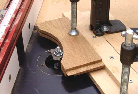
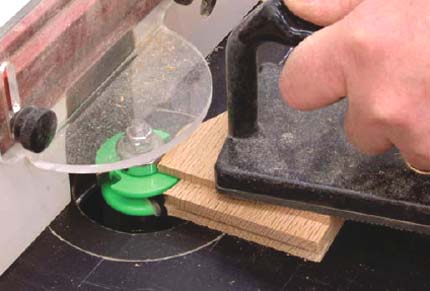
I’m not comfortable holding small curved pieces of wood when cutting grooves or profiles on the router table. My hands are too close to the cutter and have very little protection should the work piece jam or kick out.

I built this simple routing sled jig that clamps the work piece and provides handles that are well back from the router bit. It’s easy to build as you can see from the picture. Use two pieces of ½″-thick plywood, one that is narrower than the other, and attach wood dowels for the handles and a couple of screw or toggle clamps. The hardware is available at many woodworking stores.
I like this jig because it lets me get a good, full grip, with both hands, to control the work piece. If a problem does occur, I’m behind the work piece. You can see how the pieces of wood are clamped in the illustrations for building arched and cathedral doors.
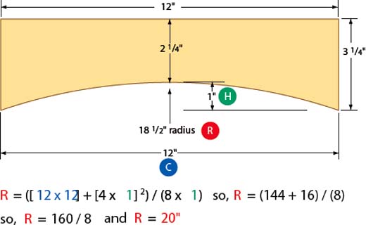
The radius of an arc for arched and cathedral doors can be calculated mathematically. A line between two points on a circle is called a chord. The arc on both cathedral and arched doors is part of a circle, and the chord is the straight line between the arc ends that meet the bottom edge of the rail.
The formula states that the chord (C) is squared (multiplied by itself) and four times the height (H) dimension squared is added to that number. The number is then divided by a figure that is eight times the height. The result is the radius of the circle in inches and indicates the spread between point and pencil on a beam or large compass.
FORMULA:

CATHEDRAL

ARCH
I’ve sandwiched this section between the section on flat panel doors and the next on cope-and-stick doors because raised panels can be used with all these doors. There are a number of techniques that can be used to “raise” a solid wood panel, but I will be focusing on the method using raised panel cutters, either in a sturdy router table, or in a shaper. Use the method that best suits the equipment you have in your shop.
There are many plain panel-raising router bits, but the most common is a simple cove style. These bits have long, medium and short radius cuts, so you’ll have to decide which profile best suits your needs.
This group of plain panel-raising bits also includes tapered cutters, which are available in a few different profiles. These bits can be used to make door center panels that can be used with many furniture styles, so it’s probably the best one to purchase for general use.

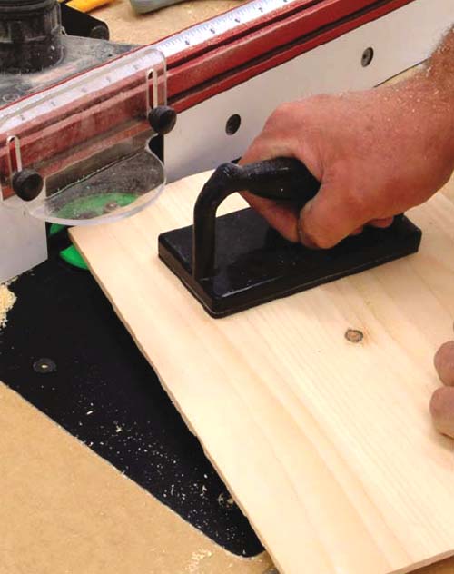
1 Install the panel-raising bit in your router, making certain that it’s properly seated and tightly locked in the chuck. Your table should be equipped with a router that’s rated at 2 horsepower or more. Many woodworkers maintain that only variable-speed routers should be used because these bits seem to cut better when the router is set at one-half or three-quarter speed. There’s a lot of truth in that belief, but I have successfully used fixed-speed routers to raise my panels. Experiment with router speed and panel feed rates to achieve clean cuts. However, even the correct speed and feed rates may not guarantee success; some types of wood, such as oak or maple, tend to splinter or tear out in chunks, so a lot of testing may be necessary.
2 It’s often better to make a number of small passes rather than one large cut with these cove panel-raising bits. Mill the end grain first, as that’s where most of the tear-out occurs; then follow up with cuts along the grain. Continue making the cutting passes until the panel edges are  thick, or the proper thickness for stile and rail frame grooves.
Figured panel-raising bits cut a pattern into glued-up panels. I’m using a common ogee-style bit.
Figured bits are often chosen to match cope-and-stick bit sets, which are used to cut tenons, grooves and patterns on the edges of door-stile members and the ends of door rails. You’ll find pattern styles called Roman Ogee, Classic Bead, Classic Frame and so on for both stile-and-rail bit sets as well as the panel-raising bit.

1 The milling steps and procedures for the figured bits are the same as those for the simple plain bits. Make a number of small passes and test the cuts on scrap material before making the final cuts on the panels.
2 The panel should be guided by a bearing on the bit using a medium feed rate to achieve smooth cuts. A certain amount of finish sanding will always be required, but you can minimize it by testing for the best feed rate and router speed.
These special bits are available in many of the standard profiles but are also equipped with a rear-cutting blade. The back cutter forms a rabbet cut on the rear face of the panel as the face is profiled. This rear cut positions the door so the front face of the frame and panel are on the same level.
1 Both front and rear faces of the raised panel are milled during a cutting pass. The double-profile cut means that a panel must be raised with only one pass per edge. There’s a lot of material being removed on each pass, so be sure your router bit is sharp; also test the feed rate as well as the router speed with scrap material before you begin.

2 Typically, a guide bearing controls the cut depth, but I always set up my router-table fence slightly behind the bearing’s front face as a safety device. The bearing is the primary control, but the fence prevents the panel from being kicked back in case of a jam. With all these cutters, dust is a major concern, so a good vacuum system is necessary.
This photo shows the edge profile on a panel that was milled with a raised-panel bit equipped with a back-cutting blade. It has a specific purpose that is best explained by studying a raised panel’s relationship to the front surface of a door frame.
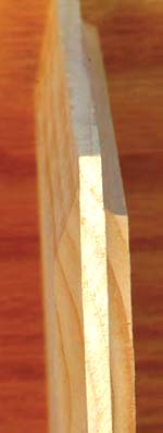
Door frames, made with two stiles and rails, have a groove in the center to hold a flat or raised panel. The stile and rail grooves can be cut on a table saw or by using a cope-and-stick bit set (see the next page).
These stile and rail grooves are normally centered on the edges, which means that a raised panel of the same original thickness (¾″-thick door-frame material and ¾″-thick raised panels) as the frame will be ¼″ higher than the front face of the stiles and rails. The panel is said to be “proud of the frame” because it’s held in the groove, which is ¼″ in from the frame’s back edge.
If you don’t mind having a raised center panel proud of the frame, then there isn’t a problem. If you want the center panel’s front face to be on the same level as the door frame’s face, you have two options.
First, you can use -thick material for the stiles and rails and -thick material for the center panel. The ¼″ difference, because the panel is in the grooves that are ¼″ above the frame’s back face, is accounted for by the thinner panel material.
The other option is to use the same thickness material for the door frame and raised center panel, but you must use a panel-raising bit equipped with a back cutting blade. The center panel’s back face will have a ¼″ rabbet, which will lower and level its position with respect to the frame’s front face. Simply put, we would remove ¼″ from the back of the panel edges so the panel would be recessed ¼″ from the front surface of the door frame.
Cope-and-stick doors are much like the tenon-and-groove doors described on page 123. The “tenon” is made with a cope bit and the “groove” on the rail and stile edges are made with a matching stick bit. They are a little more detailed than the simple tenon-into-a-groove design, but only because there are a few added cutting profiles on the bit sets.
These doors can be fitted with a ¼″-thick flat panel as shown earlier, or with one of the raised panels. The panels are held in the “stick” or groove cut by a router bit in a router table. I don’t suggest trying to use these bits freehand in a router because they are quite large and remove a considerable amount of material. I recommend using a good router, rated at two or more horsepower, and a solid router table. And even then, be sure to follow the safety recommendations explained this chapter.
There are normally two bits in a rail-and-stile cutter set. The inside edges of the rails and stiles are cut with a stick bit and the rail ends are formed to fit the stick cuts with a cope bit. There are a number of different patterns available, much like the panel-raising bits, including plain, ogee, coved and so on.
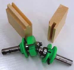
I prefer a bit set rather than the single rail-and-stile combination bit that has removable cutters for repositioning when each profile is cut. I would also suggest that you use ½″-diameter shank bits in a router capable of taking a ½″ shaft, because these bits will come under a great deal of stress.
Take a look at the cutting profile in this illustration. You’ll see the tenon-into-a-groove arrangement created by the cutting bits. Each bit set cuts a little differently, so you’ll have to calculate how much extra length is required on the rails to produce the final door size required.
Door height is equal to stile length so, if I require an 18″-high door, my stiles will be 18″ long. The rail width is another matter because the cope cutter is removing material to form the tenon. The bit set I’m using requires an added to the rail length to get the desired door width.
For example, the door I need is 12″ wide × 18″ high. My stile and rail width is 2¼″ so that width is doubled (for two stiles); subtracting that figure from the required final door width of 12″ gives me a rail length of 7½″. However, for my bit set, I know that an additional must be added to the rail length to account for the material removed in cutting. Your bit set will likely be different, so test your measurements on scrap material before you begin making doors to get the waste factor number.
Test the bit set and make a sample pattern for the stile-and-rail cutter. Keep those patterns handy so the bits can be aligned for cutting. It will save a lot of setup time.

Square cope-and-stick doors are the simplest form of this door style. They are formed with a bit set that cuts tenons and grooves. The process is similar to the tenon-and-groove doors discussed earlier but the patterns are more detailed because of the bit profiles that are used.
Set up your bit set with samples, determine the “adding” factor for rail lengths, and cut the parts to size.
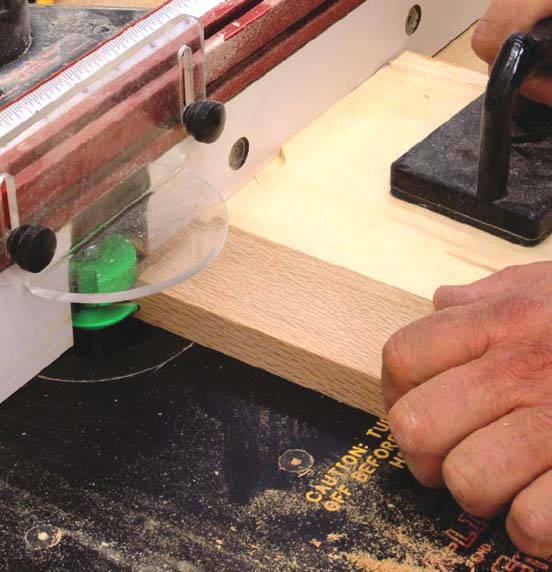
1 Cut the stile and rail parts to size. Cope the ends of each rail with a backer board behind the wood to minimize tear-out. Notice that I’m making the cope cuts first. Some woodworkers prefer this method while others cut the stick profile first. I don’t feel one way is superior to the other; I often cut my stick profiles before the rail-end cope cuts. Experiment with both methods to find the procedure that works best for you.
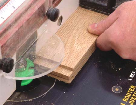
2 Once the rails have been coped, cut the stick profile on the inside edge of both rails and stiles. Before making the final cut, set up the stick bit and use scrap lumber of the same thickness as the rails to match the previously cut coped rails to the new stick setup.

3 Dry fit the door frame and measure the inside dimensions. My groove, or stick cut, depth for the bit set I’m using is . I want to leave a little room for panel and frame expansion and contraction, so I’ll add ¾″ ( plus minus ) to the inside height and width of the frame.
4 Cut the center panel to size. At this point you have two options; you can install a ¼″-thick veneer plywood center panel as shown, or a raised solid-wood panel like the ones described earlier.

5 Raised center panels begin as solid-wood glue-ups. The boards can be prepared on a table saw or by using a jointer and planer.
6 Raise the panel using a panel-raising router bit.
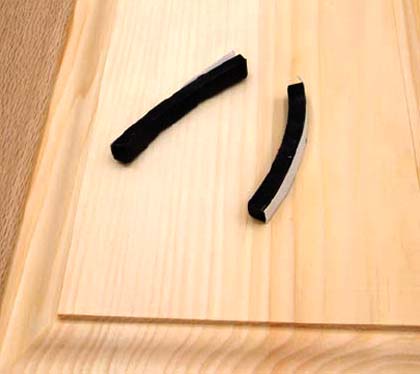
7 To reduce door panel “rattle” (because it will be loose in the frame) install small strips of soft foam in the groove. I use strips cut from a roll of soft weatherstripping material that I purchase at my local hardware store. These large rolls of foam are used to insulate doors and are commonly available as well as inexpensive. One roll of weatherstripping will be enough to do dozens of doors. You can also buy any of the commercial products made for this application from your local woodworking store.
8 Assemble the door by applying glue to the cope cuts only. Clamp the door frame and measure the diagonals to be sure they are equal, which means that the door is square. Do not glue the panel in place so it and the frame members can move as humidity levels change.

The arched cope-and-stick door is a variation of the square door. The upper rail, and sometimes both rails, has an arc pattern. The upper rail is wider because material will be removed when cutting the arc.
Maintaining fixed dimensions on all arched doors, particularly those for a project such as kitchen cabinets, makes all the doors appear similar no matter what their width. Refer to page 131 for more details on maintaining visual consistency in arched rail doors.
1 Cut all the parts to size. I usually cut straight rails and stiles 2¼″ wide and arched rails at 3¼″ wide. Draw the arc on the curved rails.
2 Use a band saw or jig saw to cut the arc. Sand the curve smooth.

3 Cope the rail ends. Remember to keep the rails oriented the same way when cutting — don’t flip them. In other words, keep the same face up when you turn the rail to cut the opposite end. Use a backer board to minimize tear-out.
4 Change to the stick bit, align and test the bit for a correct cutting pattern, then cut the straight stiles and rail.
5 The curved upper rail edge requires a stick cut. Use a push pad and carefully enter the cutter. Most router bits spin counterclockwise in a table, so the wood can be pushed backwards and onto the leading face of the bit. Hold the board securely and enter the bit’s cutting path carefully. Notice that my router fence is set slightly behind the bit to act as a backstop should the work piece be thrown back. Use care and all safety devices when cutting the curved rails.
6 The center panel can be a ¼″ thick piece of plywood veneer or a solid-wood raised panel. The simplest method to determine panel size is to lay the door frame on the panel and trace inside the frame. Notice that my upper curved rail is higher in the door frame than normal. This will allow me to draw the correct cut line for the curve, which will properly sit in the -deep groove made by the stick router bit.
7 Prepare the panel of your choice. Raising curved panels with a router bit is fairly easy as long as you push the panel smoothly through the bit and keep it tight to the bearing.
8 Apply glue to the rail ends and assemble the door. Clamp the door frame and make sure that it’s square.

Cathedral-style cope-and-stick doors are a variation of the arched door. The arc is shorter, leaving equally dimensioned straight lengths of the rail at either end. The combination of straight and arched cuts in the rail distinguishes the cathedral style. These doors are referred to by other names but to save confusion I’ll refer to them as cathedral doors.
Once again, a router stick bit will be tracked in a curve, so exercise caution and follow the previous suggestions about safe practices. If you’d prefer not to get too close to the bit with a push pad, use the curved router jig. Always wear safety glasses and hearing protection, and keep the router-table fence as close as possible to the bit as a safety precaution.
1 Cut all the parts to size. I usually cut straight rails and stiles 2¼″ wide and arched rails at 3¼″ wide. Draw the arc on the rails, leaving 1 of straight rail on either side of the arc. The arc rise at its center point is 1″; the radius formula can be used to determine the compass setting.
2 Use a band saw or jig saw to cut the arc. Sand the curve smooth.
3 Cope the rail ends. Remember to keep the rails oriented the same way when cutting — don’t flip them. In other words, keep the same face up when you turn the rail to cut the opposite end. Use a backer board to minimize tear-out.
4 Change to the stick bit, align and test the bit for a correct cutting pattern, then cut the straight stiles and rail. The curved upper rail edge requires a stick cut as well. Use a push pad and carefully enter the cutter. Most router bits spin counterclockwise in a table, so the wood can be pushed backwards and onto the leading face of the bit. Hold the board securely and enter the bit’s cutting path carefully. Once again, notice that my router fence is set slightly behind the bit to act as a backstop should the work piece be thrown back. Use care and all safety devices when cutting the curved rails.
5 The center panel can be a ¼″-thick piece of plywood veneer or a solid-wood raised panel. The simplest method to determine panel size is to lay the door frame on the panel and trace inside the frame. As with the arched door, notice that my upper curved rail is higher in the door frame than normal. This will allow me to draw the correct cut line for the curve, which will properly sit in the -deep groove made by the stick router bit.
6 Prepare the panel of your choice. Push the panel smoothly through the bit and keep it tight to the bearing. Apply glue to the rail end and assemble the door. Clamp the door frame and make sure that it’s square.
Drawers are required for many woodworking projects. You’ll find them in desks, kitchen cabinets, storage cabinets, workshops and many more applications. We need drawers to store and organize all sorts of things in every room of the house, office and workshop.
Some woodworkers believe that a drawer lacks quality unless it’s built with dovetail joinery. I don’t hold that opinion. There are dozens of ways to build high-quality drawers, and all of them have a purpose and place in modern cabinetry.
I’ll start by describing drawers made with melamine particleboard (PB) and then move on to other materials such as Baltic birch plywood and solid wood. I’ll explain some of the joinery options as well as the hardware that can be used for your drawers.
In general, the 1″ rule applies to most drawer-building projects when using modern hardware. Bottom-mounted and side-mounted slides made by manufacturers such as Blum and Accuride require a ½″ space between the outside of the drawer box and the cabinet side for proper installation and operation. Simply stated, the drawer box is 1″ narrower than the cabinet’s interior width.
The drawer opening is measured from inside edge to inside edge of the face frame. Subtract 1″ from that dimension, which will give you the drawer box’s outside width. To simplify matters, I also subtract 1″ from the drawer opening height to determine my drawer box height.
This “rule” is very general, so I suggest you read the manufacturer’s instructions packed with your hardware. One important issue to keep in mind if you plan to use the new hardware: most drawer-glide systems are designed to operate based on frameless-cabinet building styles. The cabinet’s side is the cabinet’s face and therefore the opening equals the sides’ inside face-to-face dimension. But, that doesn’t mean the hardware cannot be used with face frame style cabinets.
If the face frame’s inside width is smaller than the cabinet’s inside width, cleats or spacers must be installed to mount the glides flush with the inside of the face frame. It’s a simple matter of attaching small strips of wood to mount the hardware.
The same 1″ rule applies to most drawer-building projects when building frameless cabinet drawers. Most drawer slides require a ½?” space between the outside of the drawer box and the cabinet side for proper installation and operation.
The drawer opening is measured from the inside face of one side panel to the inside face of the opposite side panel. Subtract 1″ from that dimension to determine the drawer box’s outside width. This “rule” is very general, so I suggest you read the manufacturer’s instructions packed with your hardware.
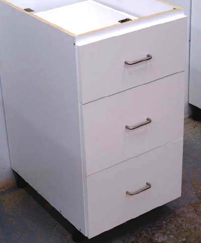
Calculating drawer-box heights for frameless cabinets is a little more involved. First, use the height measurement for a standard door in your project. For kitchen cabinets, a full-height base cabinet door is used as a reference. Drawer-face heights, plus the gap between them, should equal the height of base cabinet doors in the same project. A three-drawer base should have a combined drawer face and gap height equal the standard door height.
Decide on the height of each drawer face according to your requirements. For example, a three-drawer base could have two 10 -high bottom drawer faces and one 8″-high top drawer face, as well as two -high gaps. The total height of the faces and gaps is 30″, which should equal the standard full-height door in your project.
All drawer boxes, with the exception of the top box, are 2″ less in height than their drawer faces; the top box is 3″ less in height than its drawer face. This cabinet requires two 8-high lower drawer boxes and one 5″-high top drawer box. The lower box is installed tightly against the bottom board and the boxes need a 2″ vertical space between each other. The top box is set 1″ below the lower edge of the top rail.
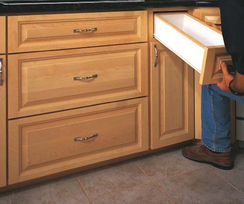
One of the most common applications for drawers and pullouts is in the kitchen. Just about every kitchen cabinet project involves drawer-building. You’ll find banks of drawers, drawer-over-door cabinets and pullouts. It’s not unusual to have ten or twelve drawers in the average kitchen. Often, these drawers are constructed using melamine PB and butt joinery secured with biscuits or 2″-long PB screws. The following steps outline an excellent method to use when building melamine PB drawers.
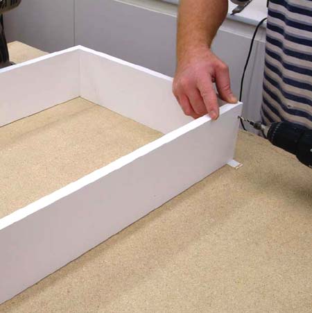
1 Cut the sides, front, back and bottom boards to size using -thick melamine PB. The exposed top edges as well as the side edges of the bottom board can be covered with heat-activated iron-on edge tape. Join the sides to the front and back boards using biscuits, glue, and clamps or 2″-long PB screws. Always drill a pilot hole and then counterbore the hole slightly before driving any screws into the joint.
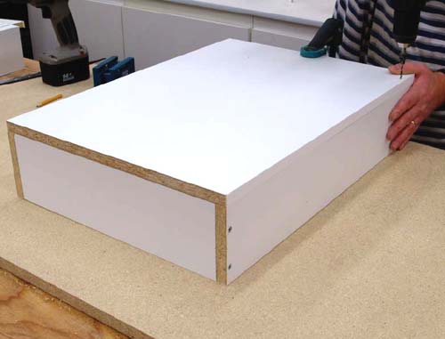
2 Attach the full-thickness bottom board with 2″ PB screws. If the bottom board was cut square, the drawer box will be square.

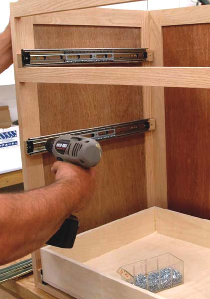
3 The drawer box can be fitted with bottom-mount drawer glides. They are aligned flush with the front edge of the box and secured with -long screws. Standard drawer-glide sets will allow the drawers to slide out of the cabinet three-quarters of their length. They are easy to install, reliable, inexpensive, and operate smoothly on nylon-bearing wheels.

4 The cabinet runners are part of the drawer-glide set and are secured to the cabinet’s sides with screws. Set them back from the cabinet’s front edge and at 90° to that edge. Use a carpenter’s square, resting on the front edge of the cabinet, to draw a reference line to help align the runners.
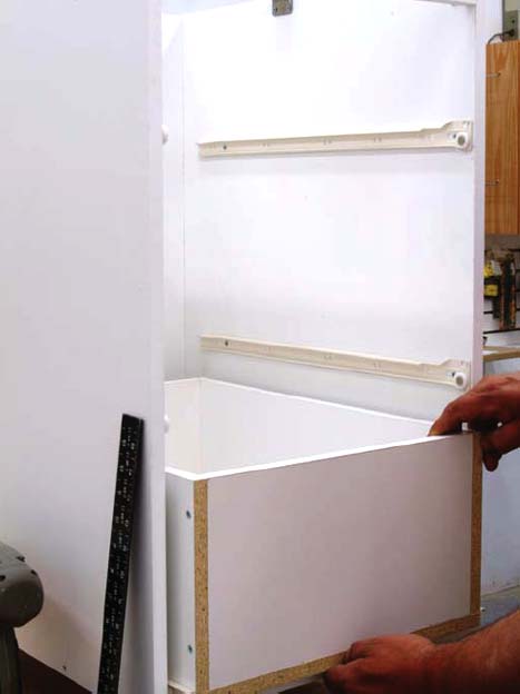
5 Test the drawer’s operation. It should slide smoothly in and out of the cabinet and rest firmly on the runners. Push down on each front corner of the drawer to test its stability. If either front corner moves down as you press, the runners must be realigned. A “bouncing” drawer corner means that the cabinet runner on that side is too high at the back end and should be lowered slightly. Test the front corners and adjust the cabinet runners until both sit firmly on the glides.
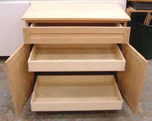
Half-inch-thick Baltic birch plywood is the favored material of many cabinetmakers for building drawer boxes. The drawer parts can be joined in a number of ways, but I’ll explain the simplest method using rabbet butt joints and brad nails.
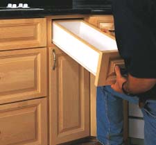
Baltic birch is also a good material to use when building pull-out drawers behind doors. It’s light, and the void-free edges can be sanded and finished.
1 Each side board has a -deep by ½″-wide rabbet on both ends to accept the front and back boards. The rabbets can be cut with a dado blade on your table saw or on a router table. The rabbet depth equals one-half the board’s thickness.
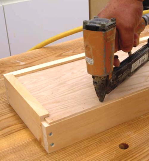
2 The drawers are assembled using glue and brad nails. Apply glue to the rabbet cuts and attach the side boards to the front and back boards. The bottom is also attached with glue and brads.
3 Install the drawer-glide hardware following the manufacturer’s instructions. Most slide hardware, as mentioned earlier, needs ½″ clearance on each side of the drawer box. For this application I used side-mount full-extension (FX) glides, but a standard three-quarter extension glide will work just as well.
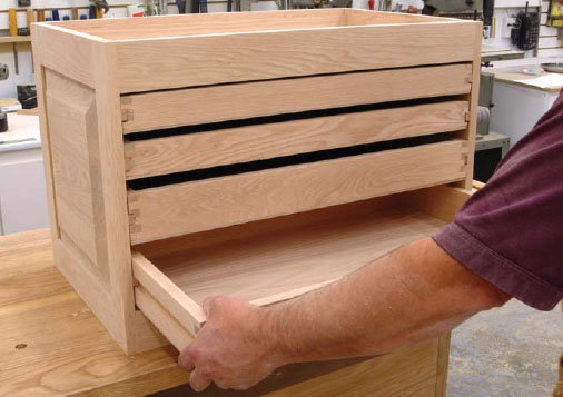
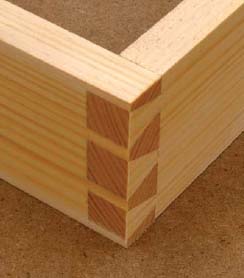
Here’s a variation of a solid-wood drawer box that can be built with finger joints. The bottom panel is nailed and glued on the bottom edge of the side, front and back boards. Another style of solidwood box, with the bottom in a groove, is shown on page 148.
This drawer box, or tray, tracks on wood runners in grooves cut along the side boards. The drawers can also be installed using conventional drawer glides, but there must be a  space on each side as explained earlier in this chapter.
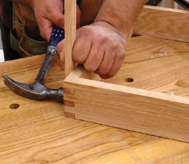
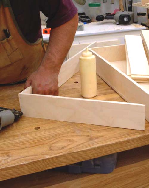
1 The trays are narrower than the cabinet’s inside width. The sides, back and front boards are  hardwood stock. I used finger joints for the corner joinery here, but many other joints can be used. If you decide to use a screw-and-butt joint, don’t place the screws in the middle of the side boards because grooves will be cut in the center.
Cut the parts to size, then set up your finger-cutting jig. Each finger and slot for these joints is wide. To properly interlock, the sides are indexed differently from the front and back boards. Remember to orient the boards properly when cutting each end. To guarantee correct positioning, place a mark on the bottom edges of the tray boards. Now, start all the cuts on both ends of each board with the mark facing the fixed pin.
Assemble the four trays with glue applied to all fingers and slots. Clamp the trays and measure the diagonals to ensure that they are square. If the measurements are different, a slight twist or tap on the long side should equalize the measurements.

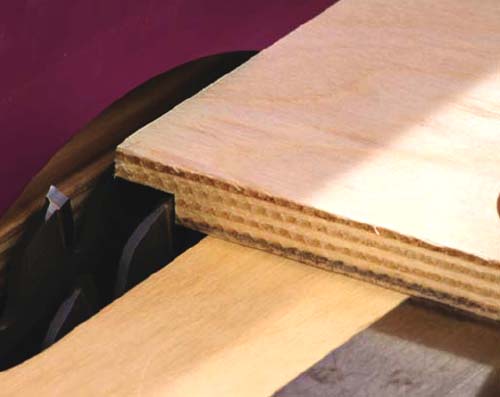
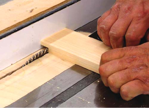
To achieve as much drawer depth as possible, glue and nail -thick veneer plywood to the tray frame bottoms. A -wide groove is needed on both sides of each tray. They will fit over solidwood tray runners and should be centered on each side.
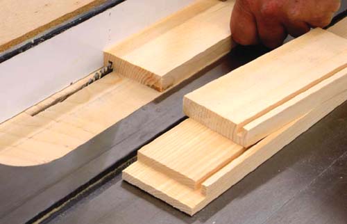
The best tool to cut these grooves is a stacked dado blade on a table saw. Begin with a -deep groove on each side and test-fit the tray. If necessary, cut the grooves a little deeper to achieve the correct fit. The tray should be snug on the slides, without binding; they can be fine-tuned with sandpaper and waxed until they slide smoothly.

The drawer-box construction standard, before the introduction of modern materials and hardware, was a box with solid-wood sides, front and back boards. Rabbet joints were used on the corners and a ¼″-wide groove was cut in the front and side boards. The back board was reduced in height to accept a ¼″-thick plywood bottom that would overlay the back edge.
The bottom board was inset because the side-board’s bottom edges tracked on wood runners. With the inset bottom, only the side edges would be in contact with the runners to reduce friction. The wood parts that contacted each other would have a coat of wax applied to reduce drag.
Many cabinetmakers still build that style of drawer today. However, an inset bottom isn’t necessary any longer because drawer boxes track on modern ball-bearing and nylon drawer-glide sets. If you plan to build cabinets to match older-styled cabinets, you may want to use the inset-bottom and wood-runner combination.
1 This sample drawer box is 9″ deep × 28 ½″ wide. The depth is 3″ at the front face. Use a dado or a standard blade on the table saw to form a -deep × ¾″-wide rabbet cut on each end of the drawer-front’s back face. If the front will be covered with a drawer face, cut the rabbets in the side boards so the ends of the joints will be hidden. I cut the front and back boards for this application because I won’t be adding a drawer face on this box.
2 The two side boards and the front all need a ¼″-wide × -deep groove on the inside face to receive the bottom board. This groove begins ¼″ above the bottom edge of each board.
3 Apply glue to the front-board rabbets and attach the sides with 1″-long brass screws or finishing nails. The grooves on the sides and front board must align to receive the bottom board.
4 The drawer’s back is 2½″ high so the ¼″-thick bottom board can be attached to its bottom edge. Attach the back board to the side board ends with glue and l½″-long screws. Slide the bottom panel into the grooves and secure it in place with a few brad nails driven into the back board. Or, you can use a rabbet joint on the back corners if desired.
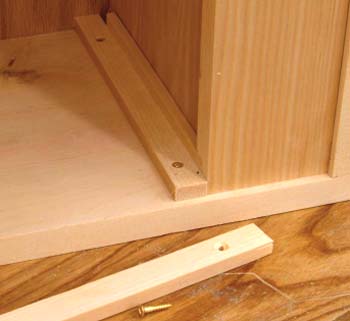
5 Drawer glides are simple, small strips of wood that are glued and screwed to the cabinet’s sides. Locate the glides so there is clearance above the drawer box. If you are building a bank of multiple drawer boxes, each with an attached drawer face, leave 1″ vertical space between boxes. The faces are applied so there’s a gap between them for frameless cabinets, or wider spaces for face-frame-cabinet drawer faces. Face-frame cabinets can be spaced more widely because there’s a rail to cover the gap.
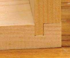
This combination joint uses a rabbet and dado to form a strong bond between the drawer’s sides, front and back. The goal is to maximize surface area, which creates a stronger bond between the two parts when glue is applied. The ¾″ surface area of a butt joint is doubled; when multiplied by the board’s length, the board-to-board contact area increases dramatically. Clamp the joint assembly until the glue sets up.
1 The dado is deep and ¼″ wide, with its back edge set ¾″ from the board’s edge. This joint is easily cut with a stacked dado blade on a table saw.
2 The rabbet is ½″ deep and long. It also is easily formed with a stacked dado blade on a table saw. Both cuts can also be made on a router table with a ¼″-di-ameter router bit.
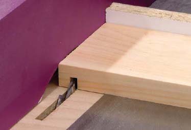
This locking rabbet joint is an excellent choice for drawer construction. Not only does it dramatically increase the glue surface area, but it also provides mechanical strength. The locking rabbet is made using a table saw and tenoning jig. There’s a little setting up to do before you cut the drawer joints, and it would be a real plus to have a stacked dado blade for your saw.
The sample drawer for this joinery project will be 3½″ high × 8″ wide by 22½″ long. I’m using solid pine with a l½″-thick veneer plywood bottom board.

1 Cut a groove in both ends of the drawer’s back and front boards that’s ¼″ wide and ¾″ deep. Center the groove using a tenoning jig and stacked dado blade.

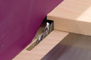
2 Remove from one side of the material forming the groove. Complete this step for both front and back boards at each end. Be sure to remove material on the same face of each board.
3 Form a dado on the inside face of each side board that’s deep and ¼″ away from each end. Notice that I’m using a backer board for many of these cuts to prevent tear-out of my drawer boards as I finish the cuts.each board.
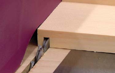
4 Cut a groove for the bottom board in the two sides and front board. The groove begins ¼″ above the bottom edges of the boards and is deep.
5 Trim the bottom edge of the back board by ½″, making it 3″ high.
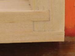
6 Assemble the drawer box with glue and clamps. The bottom ¼″-thick plywood panel is 7½″ wide × 22 long. It slides into the grooves and overlays the back board’s bottom edge. Don’t glue this panel in place; it’s held with brad nails, as illustrated.
This traditional joinery method has been in use for decades. Fine furniture, both antique and modern versions, have always been associated with hand-cut dovetail joinery. It’s one of the strongest woodworking joints available because it has mechanical strength as well as a large surface area for adhesives.
Hand-cutting dovetails takes practice, but you can easily master this joint in a short time with a little patience. There are many ways to cut dovetails. I’ll illustrate one method that doesn’t require any special alignment tools. In fact, measurements are not taken and guides are not used to make the joint shown here.
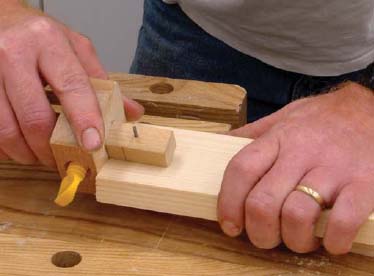
1 Use a marking gauge to inscribe lines on both faces of each board. The gauge should be set at a distance equal to the board’s thickness.
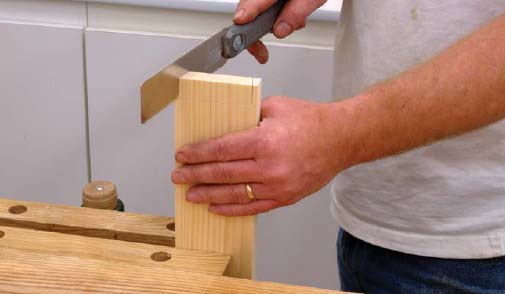
2 Cut the pins first. One half pin at both ends of the board is required. The angle is about 10° and the widest part of the half pin is about one-half the board’s thickness. The angle cut and pin size aren’t that critical because this pin board will become the template to cut the matching tail board. Be sure to cut level and straight down to the marking gauge line on each side of the board.
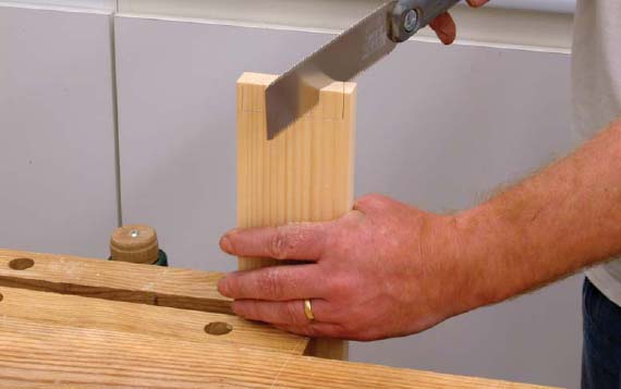
3 cut the first tail space along a line opposite to the half-pin cut. The widest part of the tail space will be approximately equal to the board’s thickness. Cut straight down to the marking gauge lines.

4 Divide the remaining space in half and cut down to the lines at the same angle as the previous cut.

5 Turn the saw to the same angle as the first half-pin cut. Divide the remaining spaces in half and cut down to the lines. These two cuts will form half pins, full pins, and full tails. Repeat the steps for wider boards. The final number of pins and tails will depend on the width of the boards to be joined.

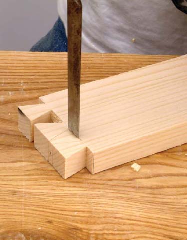
6 Chisel out the tail spaces by first cutting along the lines with a sharp chisel.
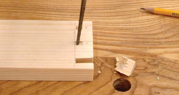
7 Chisel halfway through the tail spaces. Turn the board over and chisel the remaining halfway through the board, then carefully remove the waste.
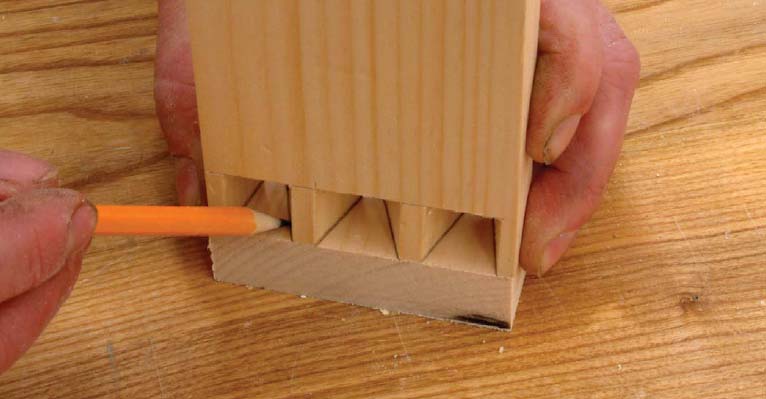
8 Use the pin board as a template to mark the tails. Mark the waste area to be removed with an X after tracing the pin outline on the tail board.

9 Cut the tail lines, being careful at this point to follow the lines. Keep the saw running accurately along the lines on the waste side of each cut.

10 Remove the half-pin waste area by cutting straight to the previously cut lines. Repeat the step on each side.
11 Cut along the marking gauge lines with a chisel and begin removing the waste. Material cannot be forced forward because of the taper on the tails, so cut through from each side and remove the waste material by pushing it out one side. Test-fit the joint and fine-tune with a file if necessary. Apply glue, assemble the joint, and clamp until the adhesive sets.
For those woodworkers who like using dovetail joinery but prefer a machine method, there are dozens of options available. The marketplace has plenty of machine offerings at a variety of prices. A router and dovetail bit are used to follow a pattern of slotted guides to form the dovetail pins and tails.

All dovetail-cutting jigs come with detailed instructions and some also provide a video about using the jig. Each machine is slightly different, so a general explanation isn’t possible. However, there are a number of excellent jigs that will allow you to make perfect dovetails for all your drawer-joinery requirements.