STEP TEN
CENTER OF INTEREST
CHANGING THE VIEW
ROOFS IN PERSPECTIVE
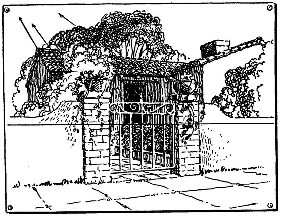
CENTER OF INTEREST
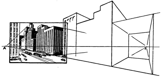
There is danger of including too much area in a drawing.
On the left of the diagram (within the frame) the drawing of the street looks quite correct in perspective.
When we extend the street to point B the buildings become misshapen.
Now if we extend the drawing to the left beyond A, the part we extend will likewise become warped.
The reason for this is that what the eye takes in is only a small area. Beyond this area the picture grows blurred and distorted.
When we extend a drawing beyond this center of interest it is necessary to turn our attention to the border of our vision. By doing this, we form a new picture. The first picture now passes to the edge of our vision or beyond. The new picture requires a rearrangement of vanishing points.
Remember that the two vanishing points will not allow you to make a panorama drawing.
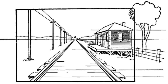
Take a further example and look down the track. The eye sees the part of the picture shown within the frame.
The area outside the frame is seen out of the so-called corner of the eye.
In this case there is the one vanishing point A; the other set of lines are parallel with the horizon line. See page 63.
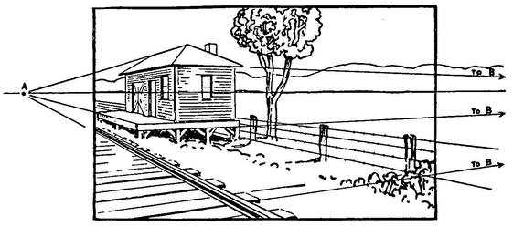
If our attention is called to the tree we turn our eyes so that the tree becomes the center of interest. Vanishing point A has moved to the left of our vision and vanishing point B comes in at some distance to the right.
This shows how new pictures are formed with a new arrangement of vanishing points when we give attention to objects that lie at the edge of our vision.
If we wish to keep our drawing correct in perspective, we do not attempt to take in a wide area.
The drawing on the opposite page is an example of the arrangement described on page 63. We change it so that it conforms to the arrangement shown on page 62. The first of the above drawings of the track represents the arrangement of the cube when it is turned to a position of one-point perspective. The second position represents the cube turned so that the vanishing point has moved toward the left.
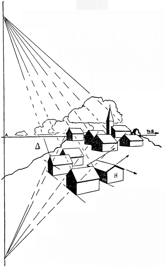
ROOFS
Often a group of roofs have the same slope. The lines of these roofs meet an up-and-down horizon line—if such a thing can be imagined.
This up-and-down horizon passes through the true vanishing point (A) of the building. This can be better understood by turning this drawing on its side.
The roof of the building H lies in the opposite direction to the other buildings; hence the vanishing points of this roof lie on a line above and below through vanishing point B. The farther apart these up-and-down points are spaced, the steeper the roofs.
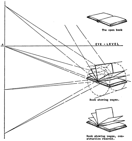
The open book or the lid of a cracker box opened to different positions is a further example of the principle used in drawing the roofs. Note the use of the cylinder in the above drawing.
REMEMBER
There is danger of including too much area in a drawing.
Two vanishing points will not allow you to make a panorama drawing.
A new picture is formed each time our attention is turned to a different point of interest.
The sloping lines of roofs meet at points above and below the normal vanishing points of the building.
PROBLEMS
Sketch a book that lies on the desk before you. Note the two vanishing points.
Sketch more books on either side of the first book. Use the same vanishing point.
How far can you extend this row of books?
How many appear well-proportioned?
Draw the end of a room with a table at the right-hand side of the drawing.
Now make another drawing of the same room end but change the view so that the table appears on the left-hand side of the drawing. What adjustment is necessary for the position of the vanishing points?
Make a sketch of a log cabin. Show the vanishing points of the roof. On the same drawing make another cabin with the roof facing in the opposite directions. Show the vanishing points of the roof.