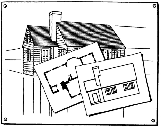
STEP TWENTY
MECHANICAL PERSPECTIVE
MECHANICAL PERSPECTIVE
We have been learning about perspective as we would use it in sketching and freehand drawing. We will now learn something about the mechanical perspective that is used in the more exacting sciences of drawing. This method is based on plans, elevations, and exact measurements of the object to be drawn. The following brief explanation is only a step in an interesting science of which there is a great deal to learn.
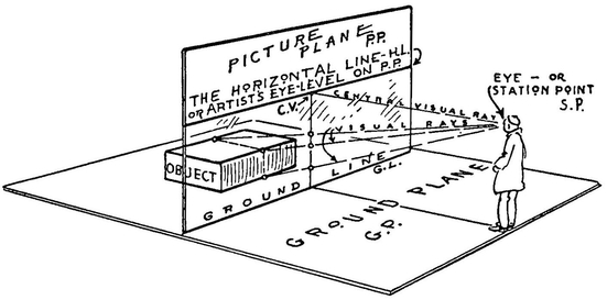
We start with the Picture Plane as it is explained on page 28. This Picture Plane (called P.P. for convenience) stands upright like a transparent wall between the object and the artist. The object and the artist are both standing on a level plane called the Ground Plane (called G.P. for convenience). The Picture Plane is perpendicular to the Ground Plane. The line where they meet is the Ground Line (G.L.).
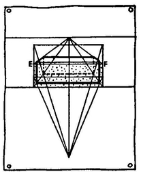
The artist sees the object through the transparent Picture Plane. Note on the diagram where three points on the object appear on this surface.
Mechanical perspective furnishes a means of locating a sufficient number of these points on the Picture Plane so that the object can be correctly drawn.
We discover that the position of these points can be changed by the artist; by raising or lowering the eye-level and by moving toward or away from the Picture Plane. We also discover that the position of the points can be changed by moving the object.
We determine the height of the artist’s eyes from the Ground Plane, then we draw an eye-level line along the Picture Plane. This is the H.L. or Horizontal Line.
Draw this familiar Eye-Level Line across a sheet of drawing paper, with the parallel Ground Line below it. The paper before us has now become the Picture Plane.
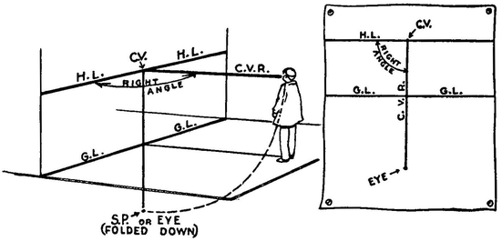
A line from the artist’s eye perpendicular to H.L. is called the Central Visual Ray (C.V.R.).
The point where this ray meets the H.L. is called the Center of Vision (C.V.).
In order to show on our plan drawing the distance between the artist and the Picture Plane (the C.V.R.) we fold the Ground Plane down from the G.L. so that it is flush with the Picture Plane. The line C.V.R. can then be measured straight down from C.V. to Eye or Station Point (S.P.) folded down.
We now have the diagram redrawn in the form of a plan on our sheet of drawing paper showing the artist’s eye-height and his distance from the Picture Plane. We are ready to begin drawing the object.
NOTE
It might be well to explain again that the term Plan as used in this STEP means looking straight down upon the object. No perspective is used in a plan.
An Elevation is a view of the side of an object with no indicated perspective.

(1)
(2)
(3)
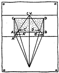
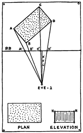
Place the object, a brick for example, in a position opposite the Picture Plane and resting on the Ground Plane. This arrangement is shown in the plan (1).
The corners of the brick are marked A, B, C, and D.
Extend lines AC and BD down to the Ground Line. This gives the true measurement of the line AB on the surface of the Picture Plane.
From these two points (where AC and BD meet the Ground Line) draw lines to the vanishing point C.V. This shows the two sides of the plan AC and BD in perspective. On these lines we must locate the plan of the brick in perspective (A′B′C′D′).
Point C.V. is the vanishing point because it is on the eye-level and also on the Central Visual Ray which is a line from the artist’s eye parallel to the receding sides of the brick. The lines of the brick perpendicular to the Picture Plane recede to this vanishing point.
Returning to the plan (2) ; draw lines from A and C to the artist’s eye. These represent the Visual Rays as shown on the diagram on page 193. Where these visual rays cross the receding line (A″ to C.V.) we have two points A′ and C′. The line A′C′ is AC in perspective. The same applies to B′D′.
Now draw the elevation of the brick as it rests on the Ground Line (3). Lines from the upper corners E and F can be extended to the vanishing point. This gives the top of the brick in perspective. With the top and the bottom of the brick located we can now determine the sides by drawing lines from A′ B′ C′ and D′ perpendicular to the Ground Line.
The brick does not necessarily have to be centered on the line C.V.R. We can solve the problem by the above method whether the brick is placed to the right or to the left of line C.V.R. providing of course the brick remains parallel with the Ground Line.
Let us try it now in two-point perspective.
So far we have considered a situation in which the face of the brick is parallel to the Picture Plane. Now we turn the brick at an angle and create the same situation as shown on page 50 (the left-hand diagram).
One way of solving angular or two-point perspective is a method used by architects. This method is the combining of the plan, the elevation, and the diagram from page 194.
ARCHITECT’S METHOD
(1)
(2)
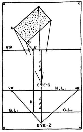
Place the brick back from the Picture Plane (Diagram 1) and show the visual rays from the EYE-1 to the corners of the plan ABCD. These rays pass through the Picture Plane at A′B′C′D′.
Now arrange this as shown in diagram (2). The new Horizontal Line, Ground Line, and Eye position are placed a convenient distance below. EYE-2 is the same distance from H.L. as EYE-1 is from P.P. The C.V.R. Line of the two diagrams becomes a continuous straight line.
We now locate the two vanishing points on line H.L.
Lines from EYE-2 drawn parallel to the two adjacent sides of the brick meet the H.L. at two points. This method is explained on page 50.
We have the plan of the brick; now it is necessary to show its height.
Extend AB until it meets P.P. at A″. From A″ draw a line parallel to C.V.R. and extend it to the Ground Line. We can now measure the true height of the brick from the Ground Line to H on this line.
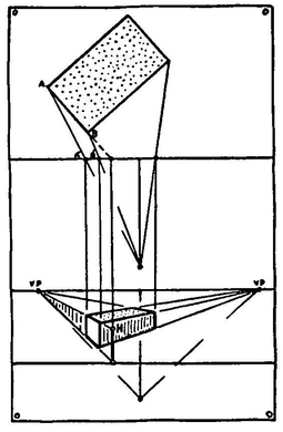
We now have the height of the brick measured on the elevation of the Picture Plane. If we carry this upright line to the vanishing point on the left we have a wall in perspective the height of the brick.
The end of the brick forms part of this wall. Now to locate it.
We know that the artist sees line AB as line A′B′ on the Picture Plane. We now project A′B′ down to the wall we have drawn in perspective. In this manner we cut off the part of the wall that is the end of the brick.
The diagram shows how the other faces of the brick are located.
When we have learned to draw a brick in mechanical perspective we have gained knowledge by which we can draw all geometric shapes: a chest of drawers, a house with gables, a temple with colonnades and domes, a cathedral with towers and buttresses.
The few rules given here are a bare suggestion of mechanical perspective. For the student who wishes to learn more of this science, there are excellent books of advanced treatment. The knowledge gained adds greatly to the artist’s power of observation and interpretation.
SHORT CUTS
Many short cuts have been developed from mechanical perspective. Here we have one used by commercial artists in determining the spacing of windows of a building drawn in perspective.
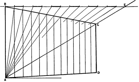
The side of a building when drawn in perspective is shown as ABCD in the diagram.
We wish to divide this space in perpendicular rows of windows; six in this case. Now how to space them.
First we draw a horizontal line through B (the top and near corner of the building).
Next we draw a diagonal line from A through C. Extend it until it crosses the horizontal line at E.
Now we divide the line B to E into the spacings of the window plan. There are six windows in this instance.
From these points we draw lines down to A. These lines pass through the top line of the building. The points where they intersect locates the perpendicular lines of the windows.
REMEMBER
Mechanical perspective is based on three principal units: the artist observer, the object, the ground line and picture plane arrangement.
Visual rays are imaginary lines from the artist’s eye to a point on the object.
Mechanical perspective should enrich and not hinder the artist’s freehand drawing.
PROBLEMS
Draw a brick in various positions using mechanical perspective.
Draw a house in the same manner.
Draw a square building with ten rows of windows on each of the sides toward you.
SUMMARY
Study the railroad track, it will furnish the fundamentals of perspective.
Learn to draw a brick, you will then have a working knowledge of perspective.
Learn all you can about the “Big Three” of perspective: the Eye-Level, Vanishing Point A, and Vanishing Point B.
Do not let the mechanics of perspective cramp your freehand drawing.
Use your knowledge of perspective to insure accuracy in your drawing and to check for error.
Learn all you can about perspective. The knowledge gained will give you confidence in your drawing and thus allow more freedom.
Sketch an object freely and naturally; try to avoid laying out a cold mechanical setting and forcing the object into it. Perspective can easily be overdone.
Remember the value of intersecting diagonals (crosslines) to find a center.
Always place the two vanishing points far apart, thus avoiding violent perspective.
Do not concern yourself about the technical placing of vanishing points in freehand perspective—their position is approximate.
Study any good technical book for the mechanical placing of vanishing points. This knowledge is very useful for mechanical renderings.
Remember the manner in which one vanishing point moves in relationship with the other. This is important.
Draw a whole city by drawing the arrangement of bricks.
Think of bricks and cylinders as the basis for most of the things we sketch in perspective.
Learn to draw a cylinder and your knowledge of drawing has been greatly broadened.
The inside of a room is the inside of a box. Learn how to draw a box.
Try drawing a checkerboard in two-point perspective. It is a good test for correct drawing.
If an object is difficult to draw because of its irregular shape, consider it as fitted inside a box; then draw the box in perspective.
Don’t attempt to include too much in a perspective drawing, the eye includes only a small area.
Consider upright or perpendicular lines as drawn parallel, having no vanishing point considered.
Think of the reflection of an object as left-handed and upside down.
Use the same vanishing points for the reflection as for the object. This is true when the object is level with the reflecting surface.
Don’t confuse a reflection and a shadow, they are not the same.