 INDICATIONS AND CONTRAINDICATIONS
W. Randolph Chitwood, Jr.
Over the past 15 years, minimally invasive cardiac valve surgery has gained worldwide traction as a standard of care for many patients and surgeons. Early reports suggested that alternative incisions and minimally invasive approaches to replace and repair mitral valves were safe and efficacious. Large series as well as several meta-analyses have confirmed that minimally invasive mitral valve surgery (MIMVS) is appropriate for many patients. Also, robotic mitral valve repair series at dedicated referral programs have shown outcomes similar to operations done either through a sternotomy or a minimally invasive incision. The economic costs often have been challenged; however, high-volume Mayo and Cleveland Clinic robotic mitral valve repair programs have shown parity with other incisional approaches.
INDICATIONS AND CONTRAINDICATIONSPatients should have the indications for mitral valve repair surgery as outlined in either the 2014 ACC/AHA (United States) or 2012 ESC/EACTS (European) Guidelines. The minithoracotomy incision, with or without assisted vision or robotics, is indicated for both primary and reoperative mitral valve surgery in patients with no or few comorbidities. Moreover, combined mitral and tricuspid valve operations can be performed safely through a mini-thoracotomy. Nevertheless, some surgeons prefer to use a hemisternotomy for MIMVS. Patients requiring either concomitant multivessel coronary revascularization, an aortic valve replacement, or have a significantly dilated ascending aorta should have a traditional sternotomy operation. General contraindications to the mini-thoracotomy approach are listed in Table 18.1.
TABLE 18.1 Contraindications: Minimally Invasive Mitral Valve Surgery
 PREOPERATIVE PLANNING
Informed consent for a minimally invasive or robotic mitral repair should include the choice of a traditional sternotomy operation as well as the possibility of conversion to a sternotomy for safety or to achieve the operative goal. Either an excellent transthoracic echocardiographic (TTE) or transesophageal echocardiographic (TEE) study should be done to determine operative necessity and to guide the operative plan. In select patients computed tomographic (CT) images should be obtained to determine the status of the peripheral vasculature and aorta as well as define any noncardiac thoracic pathology. Patients at risk for coronary artery disease either should have coronary angiography or a CT angiogram. After anesthesia preparations, a comprehensive 2D and 3D TEE study should be done in the operating room to render the necessary planning information listed in Table 18.2.
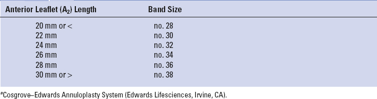
At our center all minimally invasive, robotic, and traditional mitral repairs are considered, planned, and directed from intraoperative TEE studies. To determine an appropriate annuloplasty ring or band size, we have developed a TEE-based nomogram, which has been validated with actual leaflet measurements and commercial ring sizers (Table 18.3). Because of accentuated leaflet curvilinearity associated with extreme billowing in Barlow’s pathology, TEE can underestimate actual leaflet lengths. Thus, in these patients direct linear measurements of each leaflet segment should be made after cardiac arrest.
Long anterior leaflets (>30 mm A2), especially in the presence of a high (long) posterior leaflet (>20 mm), a narrow aortomitral plane angle (<120 degrees), or a thickened outflow interventricular septum, may portend the development of postrepair systolic anterior motion of the anterior leaflet. This can create a major hemodynamic problem when weaning from cardiopulmonary bypass (CPB). Preventative structural repair measures should include: (1) Implantation of a large ring/band, (2) reduction of the posterior leaflet height to 15 mm or less, and (3) achievement of an optimal leaflet coaptation surface (8 to 10 mm). In the arrested heart the saline ventricular pressure test, done after the final repair, is helpful to determine the degree of leaflet coaptation level and symmetry.
TABLE 18.2 Transesophageal Echocardiographic Planning Data
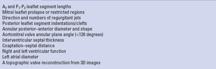
TABLE 18.3 Echo-Based Annuloplasty Banda Sizing
In general preoperative patient positioning, anesthesia management, echocardiographic evaluation with repair planning, the operative set-up, and perfusion techniques are the same for all of our robotic and nonrobotic MIMVS. For both approaches the patient should be positioned with the right chest elevated by 30 degrees on a commercial lift or a cloth roll. The right arm should be distracted laterally and supported safely inferior to the posterior axillary line. The right axillary area should be exposed to insert the transthoracic aortic cross-clamp. Standard skin preparation and draping should provide wide exposure to the right chest, sternum, and both groins.
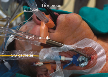
In most operations our anesthesiologists prepare patients as shown in Figure 18.1. These preparations include placing the following:

Figure 18.1 Anesthesia preparation for videoscopic and robotic mitral valve surgery. TEE probe, transesophageal echocardiography; ET tube, double lumen endotracheal tube; SVC, superior vena cava; SG, Swan–Ganz.
 SURGERY
Today, most minimally invasive and robotic mitral valve operations are performed through a right-side fourth intercostal mini-thoracotomy. The choices for visualization include a direct view through the incision, 2D endoscopic, or 3D robotic. Recently 3-D non-robotic endoscopes have been developed. The size of the working incision usually relates to both the visualization and operative method chosen by the surgeon. For both direct vision and 2D endoscopic MIMVS, a 4- to 5-cm mini-thoracotomy is made in the fourth intercostal space at the anterior axillary line. Smaller port-access incisions (2 to 3 cm) are made in the same area for robotic operations. We place a flexible Alexis soft tissue wound protector (Applied Medical, Inc., Rancho Santa Margarita, Calif.) in preference to using a rib-spreading retractor. We have found that this minimizes postoperative pain and provides good working-incision exposure for either direct vision, endoscopic, or robotic MIMVS.
All perfusion cannulas are placed under echocardiographic guidance using the Seldinger guidewire technique. The right femoral artery is cannulated with either a 17-Fr or 19-Fr Bio-Medicus cannula through a 2-cm oblique groin incision. For inferior vena caval drainage, either a 22-Fr (single stage) or a 23-Fr/25-Fr (dual stage) RAP femoral venous cannula (Estech, San Ramon, CA) is passed into the right atrium (Fig. 18.2). Vacuum-assisted venous drainage is used in all of these operations. Intrathoracic carbon dioxide is insufflated throughout each operation to minimize the amount of intracardiac air entrapment. To monitor adequate limb perfusion, during CPB, oxygen saturation levels are monitored continuously in each leg using the Invos system (Somanetics Inc., Troy, MI). If a significant arterial saturation decrease occurs in the cannulated leg during CPB, we place a distal superficial femoral artery 5-Fr catheter and connect it to the arterial perfusion circuit. To date, we have had no problems with residual leg ischemia.

Figure 18.2 Arterial and venous perfusion cannulas. Through a 2-cm right groin incision, 4-0 polypropylene purse-string sutures are placed along the anterior adventitial surface of the common femoral artery and vein. Using the Seldinger guidewire technique and under echocardiographic guidance, either a 22-Fr (single stage) or a 23-Fr/25-Fr (dual stage) RAP femoral venous cannula (Estech, San Ramon, CA) (VC) is passed into the right atrium. Similarly a 17-Fr or 19-Fr Bio-Medicus (Medtronic, Inc., St Paul, MN) arterial cannula (AC) is passed into the common iliac artery.

Figure 18.3 Transthoracic aortic clamp.
For aortic occlusion, we use a transthoracic cross-clamp (Scanlan International, St. Paul, MN) as it has been proven to be safe, reliable, economic, and simple to apply (Fig. 18.3). The posterior clamp tine should be passed through the transverse sinus under either direct or videoscopic vision. The anterior tine is positioned across the aorta until it reaches the main pulmonary artery (Fig. 18.4). Care must be taken not to injure the right pulmonary artery, left atrial appendage, left main coronary artery, or aorta.
Some surgeons prefer to use endoaortic balloon occlusion. This technique has a steeper learning curve than using the clamp. The balloon position must be precise and remain stable in the ascending aorta. There is a potential for either innominate artery occlusion or intraventricular displacement. Therefore, TEE monitoring of balloon position throughout the operation is mandatory. Also, balloon catheter introduction through the femoral arterial cannula can limit perfusion flow. In this circumstance the endoballoon catheter should be inserted through the other femoral artery. Despite these concerns, this method can provide effective aortic occlusion, a route for delivering antegrade cardioplegia, and an air vent without needing a separate aortic root cannula.
As mentioned, we have always used the transthoracic aortic clamp method for both minimally invasive and robot-assisted mitral valve surgery. A pledgeted diamond-shaped 4-0 PTFE purse-string suture is placed in the ascending aorta and proximal to the fatty fold of Rindfleisch. For antegrade cardioplegia administration, a long cardioplegia-vent catheter (Medtronic, Inc., St Paul, MN) is inserted through the purse strung suture, secured and then passed either through a chest wall trocar or the working incision. This catheter is inserted either under robotic, endoscopic, or direct vision (Fig. 18.5).
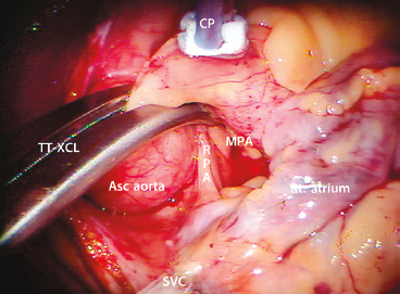
Figure 18.4 Transthoracic aortic clamp—positioned through the transverse sinus. TT-XCL, transthoracic cross-clamp; Asc aorta, ascending aorta; MPA, main pulmonary artery; RPA, right pulmonary artery; CP, cardioplegia/vent catheter; SVC, superior vena cava; Rt. atrium, right atrium. Note that the clamp is positioned cephalad to the pericardial–SVC junction.
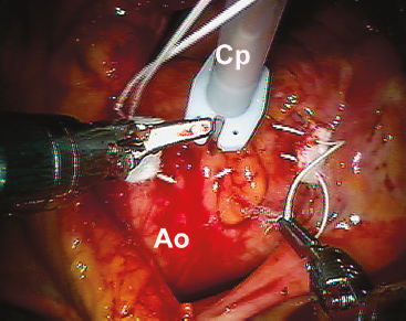
Figure 18.5 Cardioplegia/vent catheter insertion. The cardioplegia/vent catheter is placed in the ascending aorta through a 4-0 pledgeted PTFE “purse-string” suture just proximal to the fatty aortic fold.
Recently, our group switched from blood cardioplegia to Custodiol–Bretschneider’s HTK solution (Franz Köhler Chemie Bensheim GMBH, Germany) as it provides much longer myocardial protection without requiring frequent reinfusions. For maximal myocardial protection, we combine this antegrade cardioplegia with a systemic blood inflow temperature of 28°C. If blood cardioplegia is used, repeat administrations should be delivered at 15- to 30-minute intervals. Multiple cardioplegia infusions, requiring atrial retractor relaxation and repositioning, can entrain air into the aortic root.
For patients having had a previous sternotomy, we cool the patient systemically to 26°C and induce ventricular fibrillation by rapid pacing with a custom Swan–Ganz catheter. In patients with mild aortic insufficiency, additional intracardiac suction can be combined with dropping perfusion flow briefly for difficult suture placement.
After going on CPB, the pericardium is opened longitudinally approximately 3 cm anterior to the phrenic nerve, using either long-shafted endoscopic or robotic instruments. Two to three well-spaced pericardial retraction sutures are placed along the inferior (dorsal) pericardial edge (Fig. 18.6). By passing the needle through the end loop, only one suture is withdrawn through the chest wall using a crochet hook instrument. Care should be taken not to stretch or injure the phrenic nerve. The anterior (ventral) pericardial edge is then suspended with two sutures that are brought through the working incision.
2D Endoscopic MIMVS
After completing the above maneuvers and establishing cardiac arrest, we pass a 5-mm high-definition 2D endoscope (KARL STORZ GmbH & Co. KG, Tuttlingen, Germany) through a third intercostal space trocar and attach it to a hand-positioned holder (Fig. 18.7). Alternatively, a larger incision can be made for direct viewing of the mitral valve operative field. The left atriotomy is made just medial to the right superior and inferior pulmonary veins.
A transthoracic atrial retractor arm (Atrial Lift System, ESTECH, San Ramon, CA) is passed through the chest wall, just medial to the sternum in the fourth interspace, and coupled to the appropriate size blade. This arm is then attached to a table-mounted support that facilitates lifting of the interatrial septum. After adjusting the retractor for optimal exposure, the mitral valve repair or replacement is done using long-shafted instruments. For annuloplasty band/ring and valve prosthesis suture organization, we use Gabbay–Frater suture guides (Teleflex Medical, Research Triangle, NC), placed externally around the working incision. Long-shafted instruments are used for endoscopic and direct vision MIMVS and provide good rotational ergonomics, but remain without the advantage of full articulation.

Figure 18.6 Suture “loops” for pericardial retraction and left atrial closure. Tiny PTFE loops are created from or 2-0 Ti-cron sutures. A: After passing the needle through the pericardial edge, it is threaded through the loop. B: Thereafter, the suture is withdrawn through the chest wall using a crochet hook instrument. C: Two or three sutures are used to distract the pericardial edge (pericardium) laterally, exposing the right superior pulmonary vein (RSPV), aorta (Ao), right atrium (RA), and superior vena cava (SVC). D: For left atrial closure, we use a 3-0 Gore-Tex suture loop on a PH-21 needle (W. L. Gore & Associates, Inc., Flagstaff, Arizona).
3D Robot-assisted MIMVS
Robot-assisted cardiac surgery should be called surgical telemanipulation as the term “robot” means autonomous. The da Vinci surgical system (Intuitive Surgical, Inc., Sunnyvale, CA) merely provides access with superb visualization and enhanced ergonomics, which allows surgeons to perform complex operations through small port-like incisions. When using long hand-held instruments, the working incision becomes a fulcrum that can limit accurate suture placement and tissue manipulation. The accuracy achieved with da Vinci instruments relates to wide freedom of motion at the operative plane. The surgeon always has control of instruments by telemanipulation, as if they were activated directly by his/her hands.

Figure 18.7 Videoscopic set-up. For nonrobotic mitral surgery a 5-mm Storz videoscopic camera (2D vision) is placed via a trocar through the 3rd intercostal space and attached to a fixed holder. The transthoracic cross clamp (TT-XCL) is shown placed through the fourth intercostal space. Non-rib–spreading soft tissue retractor is through the 4th intercostal space working incision. An intrathoracic carbon dioxide insufflation catheter and left atrial sump are shown.
An organized team is paramount for a successful robotic cardiac surgical program. This includes anesthesiologists, surgeons, tableside assistants, scrub personnel, circulating nurses, and perfusionists. Team and procedure training at an experienced robotic valve center has been very important when launching successful programs. Surgeons should be accomplished at mitral and tricuspid repairs before beginning this new trek. Before applying robotic methods, the team should master needed peripheral perfusion techniques as well as operating through minimally invasive incisions. After team comfort has been achieved, progression to robotic mitral valve operations is reasonable and gratifying. It is important to remember that robotic instruments are only access tools and not the operation.
The da Vinci surgical system consists of telemanipulators with microinstrument (end effectors) that are controlled remotely from the surgeon’s operating console. Currently, this device is the only robotic system approved and available to perform intracardiac surgical procedures. Currently, we are using the da Vinci SI HD (high-definition) dual console surgical system, which first was commercialized in 2009 (Fig. 18.8). A new da Vinci XI System (2014) has just been approved by FDA, but has not been used widely for mitral valve surgery (Fig. 18.9). The new da Vinci XI has a laser targeting system that facilitates docking and instrument engagement. Both systems are composed of an operating console, an electronic vision cart, and a surgical instrument cart.
For mitral valve surgery the instrument cart should be positioned along the patient’s left side with the instrument activators arching over to the right chest (Fig. 18.10). Individual instrument trocars are inserted through specific intercostal spaces. After the two instrument arms, the 3D camera, and dynamic retractor have been inserted, two hand-driven sensors transmit instructions from the surgeon to instrument end effectors. A clutching mechanism enables frequent hand position readjustments to maintain an optimal ergonomic attitude with respect to the visual field.
Both the da Vinci SI and XI have dual-console capability which enables surgeon collaboration during complex cases and facilitates training. The robotic EndoWrist instruments have seven degrees of ergonomic freedom, and allow tremor-free dexterity with both dominant and nondominant hands. Thus, the wrist-like microinstrument articulations improve dexterity in tight spaces.

Figure 18.8 da Vinci SI surgeon operating console. A: Dual operating console. B: Surgeon’s “flight deck.” Instrument activators (A). LHS, left hand sensor; RHS, right hand sensor; ICP, instrument control panel. The ICP effects alterations in video magnification, transfers of instrument operation to the second console surgeon, and insertion of echo images into the operative field via Tile-Pro software.

Figure 18.9 da Vinci XI surgical system (2014). A: da Vinci XI surgeon operating console. B: Patient side instrument cart.
Correct instrument arm trocar-port placement is paramount to achieve optimal robot-assisted ergonomics. Thus, we mark a “topographic surface map” prior to patient positioning and skin preparation (Fig. 18.11). Some surgeons guide trocar placement from a recent CT scan. However, most often, these can be inserted through specific intercostal spaces and guided by camera visualization. The goal is to provide the best converging trajectory at the mitral valve annular plane. During trocar insertion, the most important anatomic landmark has been the right superior pulmonary vein.

Figure 18.10 da Vinci instrument cart positioning for mitral valve surgery.

Figure 18.11 Topographic surface map—robot-assisted mitral surgery. Topographic marks are placed along the right hemithorax just before 30 degrees elevation and skin preparation. MSL, midsternal line; MCL, midclavicular line; AAL, anterior axillary line; PAL, posterior axillary line; LA, left instrument arm; RA, right instrument arm; C, camera port; WI, working incision; LAR, left atrial retractor.
Figures 18.12 and 18.13 show ideal trocar entry sites as well as instrument insertions. Most often, left and right instrument trocars are inserted in the third and fifth intercostal spaces, respectively. The left trocar is positioned near the anterior axillary line and the right one at the midaxillary line. The 3D endoscopic camera is inserted either through the fourth interspace working incision or a trocar placed anterior to it in the same interspace. The dynamic retractor is inserted through a midclavicular line trocar placed in the fifth interspace. The most common EndoWrist instruments used for robot-assisted mitral valve surgery are shown in Figure 18.14. The dynamic left atrial retractor provides ideal mitral valve exposure and is very easy to reposition.
After the da Vinci system instruments are “trocar-docked” at the operating table, CPB is begun, and the pericardium is opened and distracted laterally as described previously. We place the aortic purse-string suture and cardioplegia cannula using robotic instruments. We perform right-sided cryo-MAZE lesions before going on CPB. After the left atriotomy is made, the dynamic retractor is manipulated to expose lesion sites specific for a left atrial cryo-MAZE.
To establish a structurally sound repair, we generally follow the operative philosophy and techniques prescribed by Carpentier. However, modifications and simplifications of these methods remain the mainstay of our repair strategy. Table 18.4 shows our “Technique Toolbox” that we use for both robotic and videoscopic mitral valve repairs.
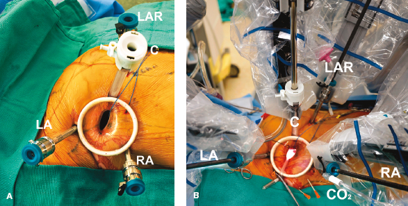
Figure 18.12 Robotic instrument set-up. A: Instrument arm trocars are inserted around the working port. B: The instrument cart has been docked at the patient just before beginning cardiopulmonary bypass and the mitral operation. LA, left instrument arm (3rd intercostal space [ICS]); RA, right instrument arm (5th ICS); LAR, left atrial retractor (4th ICS); C, 3D HD camera (4th ICS); S, intra-atrial suction catheter; CO2, carbon dioxide insufflation port. The working incision is shown in the 4th ICS. The aortic cross-clamp (3rd ICS) has not been placed.
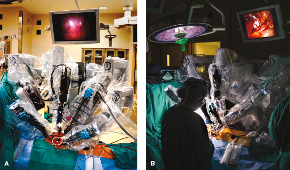
Figure 18.13 Robot instrument cart positioned. A: The instrument cart is shown docked at the operating table to the robot instruments. B: The patient-side assistant is shown in the operative environment during a mitral valve repair.
Our practice has been to maintain the integrity of the leaflet-annular junction, when possible. For all mitral leaflet repairs, we have used polyamide monofilament 4-0 Cardionyl sutures (Peters Surgical, Paris, France) to close resection defects with interrupted figure-of-eight sutures. For thick leaflet tissue, these can be closed either with a two-layer running monofilament or PTFE suture. For isolated scallop prolapse or chordal ruptures, we prefer triangular/trapezoidal resections that do not extend to the annulus (Fig. 18.15). In Barlow’s disease with multiple elevated posterior leaflet scallops, several triangular resections can produce an effective repair. Also, PTFE neochord implantation (Gore-Tex—Gore, Inc. Phoenix, AZ) has been very helpful to reduce prolapsing posterior leaflet segments. For very large isolated P2 scallops, we use the “haircut” repair technique, amputating the leaflet tip to the desired length. Good natural regional chords are then reimplanted along the coapting edge for support.

Figure 18.14 Robotic mitral operations: most frequently used instruments. A: Resano tissue forceps. B: Suture-cut needle holder. C: Curved scissors. D: Dynamic left atrial retractor.

Figure 18.15 Posterior leaflet reduction: triangular leaflet resection. For isolated posterior leaflet prolapse, often a small triangular resection is effective. This simple technique brings intact edge chords medially, reducing the level of prolapse effectively. For larger leaflets a trapezoidal leaflet resection to the annulus can be done. We prefer to close the remaining defect with interrupted monofilament sutures. A: Shows an isolated chord rupture with P2 prolapse. B: A small triangular resection is done. C: Either interrupted or a continuous suture closes the defect. D: The completed repair is shown.
Also, we have used various folding plasty and leaflet imbrication techniques when repairing the posterior leaflet (Fig. 18.16). All of these methods have been used when single as well as multiple long scallops require reduction to achieve even leaflet coaptation. For folding plasties, we pass a 4-0 PTFE suture from the annulus, through the leaflet tip, and back through the annulus. After the annuloplasty band/ring insertion, we adjust individual scallop lengths by folding to create a symmetric coaptation line. In severe Barlow’s degeneration we have substituted large resections, requiring a sliding plasty, with folding plasties, triangular resections, and neochord reductions. Nevertheless, there are times when we still use the sliding technique for a complex posterior leaflet repair (Fig. 18.17).
TABLE 18.4 “Technique Toolbox” Used for Robotic and Endoscopic Mitral Valve Repairs
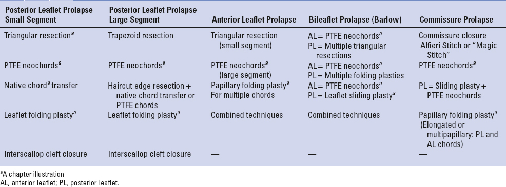

Figure 18.16 Posterior leaflet reduction: folding plasty. For prolapsing posterior leaflet segments (“scallops”), folding plasties also have been effective. A: This illustration shows a 4-0 PTFE suture passing through the prolapsing leaflet edge and through the annulus. B: The other suture end subtends the width of the leaflet edge, passing through it, and back to the annulus. C, D: After the annuloplasty band has been implanted, individual segments are folded to form an even line of coaptation. Thereafter, sutures are tied.
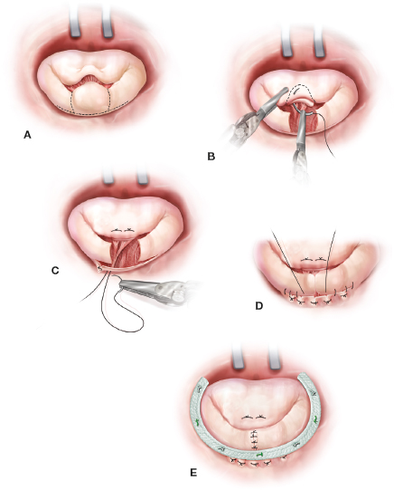
Figure 18.17 Posterior leaflet reduction: sliding plasty. A: For very long (high) posterior leaflets (especially Barlow’s disease) a large resection with a sliding plasty may be indicated. B: In this illustration a large P2 has been resected and transferred to the anterior leaflet to correct the A2 prolapse. C: Thereafter, radial leaflet incisions are made leaving a 1- to 2-mm tissue strip along the annulus. Mural chords must be divided to mobilize the residual leaflet medially. D: Thereafter, compression sutures may be used to reduce the muscular annular distance when residual leaflets are (“slid”) medially. The remaining posterior segments are advanced along the annulus (4-0 PTFE continuous suture) and reapproximated (5-0 monofilament interrupted sutures). E: Thereafter, an annuloplasty band is implanted to support the repair.

Figure 18.18 Anterior leaflet reduction: chordal strip “translocation.” A: When the entirety of the anterior leaflet is prolapsing, a strip of chord-bearing leaflet edge can be translocated and advanced along the remaining A1-A2-A3 segments. B, C: The illustration shows that the segment is being transferred along the anterior surface and reattached using 4-0 monofilament sutures. In this way anterior chords are “de facto” shortened, reducing the prolapse symmetrically. D: Thereafter, an annuloplasty band is implanted.
For all anterior leaflet repairs, we have abandoned Carpentier’s chordal shortening method that tucked an elongated chord into a papillary trench. Our focus now is correction at the leaflet edge. Currently, the most common methods used include small triangular leaflet edge resections, chordal transfers, and prosthetic PTFE chord replacements. The da Vinci 3D high-magnification camera and microscissors also allow us to detach anterior leaflet secondary chords and transfer them directly to a flail or prolapsed edge.
When the entirety of A1 through A3 is prolapsed, a wide A1, A2, and A3 chord-bearing leaflet strip can be translocated (shifted) along the anterior leaflet and toward the aortomitral hinge (Fig. 18.18). This will provide a symmetric corrective reduction of the anterior leaflet and restore natural coaptation. For single-site anterior prolapse, any resected chord-bearing posterior leaflet part can be transposed anteriorly. Residual commissural prolapse can be corrected either by the edge-to-edge method or other methods described below. Small isolated areas of anterior leaflet prolapse or chordal rupture also can be treated effectively by a limited triangular resection.
Segmental and global anterior or posterior leaflet prolapse can be reduced effectively by inserting either 5-0 or 4-0 PTFE neochords. Here, we prefer the Frater–David technique with one 5-0 or 4-0 PTFE suture passed through an adjacent papillary muscle head and a second suture passed in the opposite direction, creating a tendon repair type of “sling” (Fig. 18.19). Thereafter, both sutures are brought side-by-side through the ventricular aspect of the prolapsing leaflet. Then, they are looped over the edge and passed back through the leaflet. This locks the loop and helps when adjusting neochord final lengths using the saline test. Proper neochord lengths can be estimated from measurements of adjacent normal chords. To achieve symmetric leaflet coaptation, we implant the annuloplasty band/ring before final neochord adjustment. Other institutions have used the “Leipzig Loop” PTFE technique with great success.
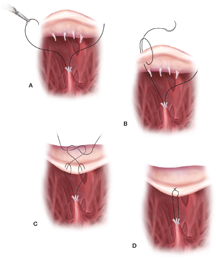
Figure 18.19 Anterior or posterior leaflet reduction: PTFE neochord. Insertion. Neochord implantation is a very effective technique to reduce both anterior and posterior leaflet prolapse. A: Either a 5-0 (posterior leaflet) or 4-0 (anterior leaflet) PTFE suture is passed at an angle through the head of an adjacent papillary muscle. The other end is passed back through the papillary head in the opposite direction affecting a “tendon-like repair” suture sling. B, C and D: Then, each end of the suture is passed through the prolapsing leaflet. Thereafter, each suture is looped around the leaflet edge and passed back through the leaflet body, creating a locking arrangement. After an annuloplasty band has been implanted each set of neochords are adjusted using adjacent normal chord lengths and the saline pressure test.
There are several strategies for severe either P1-A1 or P3-A3 commissural prolapse. These include suture commissure closure, papillary muscle shortening, and neochord implantation. For limited prolapse the commissure can be closed. Severe bileaflet (A3 and P3) posterior commissure prolapse can result from either thin elongated or separate mobile papillary muscle heads, where multiple chords support both leaflets. Shortening either a single or multiple papillary muscle heads can reduce both prolapsing commissure leaflets simultaneously. Figure 18.20 shows a PTFE suture first introduced through the papillary muscle fibrous head and then passed through the base. Upon tying the suture, the papillary muscle becomes shortened, reducing multiple A3 and P3 chords simultaneously and rendering better commissural leaflet coaptation. Anterior commissure prolapse from this anatomy is less common as most papillary muscles have a single head with all chords supporting effectively both commissural leaflets.
Annular dilatation is present in most patients with degenerative mitral valve disease. We perform an adjunctive annuloplasty in all repairs to restore the native geometry, reduce the annular size, prevent further dilatation, and reinforce the repair. Reducing the anterior–posterior annular diameter increases the leaflet coaptation surface. As mentioned before, annuloplasty band sizes are selected from our intraoperative echocardiographic nomogram shown in Table 18.3. For consistency and ease of implantation, we use the Cosgrove–Edwards Annuloplasty Band System (Edwards Lifesciences, Irvine Calif.) in most robotic and minimally invasive mitral repairs. Generally, a “Trigone-to-trigone” posterior band provides optimal coaptation while preserving a “saddle-shaped” systolic configuration.

Figure 18.20 Commissure reduction: papillary muscle shortening— reducing multiple chords. A: This illustration shows a large posterior commissure prolapse involving both A3 and P3 segments. Here chords, attached to both prolapsing segments, emanate from a single and often elongated or mobile papillary muscle head. Both leaflet segments can be reduced along with all chordal lengths simultaneously by shortening the culprit papillary muscle. B: Generally, this is done by making a small triangular resection in the midpapillary muscle and C: then folding the tip toward the defect with interrupted sutures. Attaching a mobile papillary muscle to either the adjacent ventricular wall or another “fixed” papillary muscle can stabilize it and prevent prolapse during systole.
We first place sutures at the right fibrous trigone, and continue in a clockwise direction. Previously, we instrument tied interrupted either 2-0 Ti-Cron (Covidien, Mansfield, MA) or 2-0 Cardioflon (Peters Surgical, Paris, France) sutures to secure annuloplasty bands. The Cleveland Clinic group has shown great success in using a continuous annuloplasty band suturing technique. For over a year, we have used the automated Cor-Knot (LSI Solutions, Victor, NY) device to suture secure annuloplasty bands (Fig. 18.21). After passing both 2-0 Ti-Cron sutures through the band, they are brought through a wire loop. The suture-bearing loop is withdrawn through both the applier and the titanium shim. After applying countertraction at the annuloplasty band, either through the working incision or inside the chest, the device secures and cuts the suture. This method has reduced our cross-clamp times dramatically.
Although tissue excision and suturing methods are similar in robotic and all of our MIMVS operations, there are differences in the operative conduct. In some rheumatic valves, leaflet and chordal excision can be difficult using the robotic technique. Current articulated instruments do not have the necessary force to cut very thick or calcified tissue. In this circumstance we make a larger 5- to 6-cm working incision and excise the thick leaflet and chordal tissue using long manual instruments. We then place all subvalvular valve pledgeted sutures and neochords using da Vinci system. Chord-sparing replacements are done either by excising the anterior leaflet midportion and leaving natural chords intact or by removing them to increase the prosthesis valve size and replacing them with PTFE neochords. We attempt to preserve all native posterior leaflet chords by passing sutures through the leaflet edge and back through the annulus. In patients with a severely calcified rheumatic valve or annulus, we may defer to either the 2D endoscopic or direct vision method for a replacement.

Figure 18.21 Cor-Knot suture fixation: annuloplasty band. A: A braided 2-0 suture is passed first through the annuloplasty band (AB) and tissue. Thereafter, suture ends are withdrawn through the steel wire loop (loop), which passes through the Cor-Knot applier (CK applier). (Cor-Knot LSI Solutions, Victor, NY). B: The loop with the entrapped suture is withdrawn through the device, loaded with a tiny titanium shim, and out through a side hole. Then, suture tails are pulled tight while applying countertraction to the band. Thereafter, the device is fired, crimping the shim on to the suture and cutting it. C: Completed annuloplasty. RNH, right needle holder.
Gabbay–Frater guides are placed around the working incision to organize sutures securely as they are placed. Valve sizers are then passed through the working incision, and the appropriate prosthetic valve is selected. Thereafter, sutures are passed extracorporeally through the prosthetic valve sewing ring before lowering it valve into the native annulus. After confirming valve seating, sutures are secured using the Cor-Knot technique (Fig. 18.22). A ventricular vent is placed before closing the left atrium and removing residual air. Currently, for all endoscopic and robotic mitral valve operations, we use 4-0 PTFE sutures with pretied end loops to close the left atrium. This technique provides a secure closure and saves operative time (Fig. 18.6).
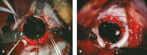
Figure 18.22 Robot-assisted mitral valve replacement. A: After robotic chord-sparing (or PTFE replacement) anterior leaflet excision, subannular pledgeted 2-0 braided sutures are placed circumferentially and exteriorized. These are arranged around the working incision in suture guides. After passing sutures through the valve sewing cuff, the prosthesis is lowered into place. B: Using the Cor-Knot suture fixation technique, the table-side assistant secures the prosthetic valve in place. This method can be used with either mechanical or biologic prosthesis.
In general, these operations have been done in patients having had prior coronary artery bypass surgery in the presence of an intact internal thoracic artery. Some of these patients have classic Carpentier type 3B ischemic insufficiency and others have a dilated annulus (type 1). We have done a minority of reoperations in patients with a failing mitral bioprosthesis.
As mentioned before, we systemically cool these patients to 26°C and induce ventricular fibrillation by rapid pacing. In the presence of a normal aortic valve, intra-atrial pulmonary vein blood can be managed with a single sump sucker. In patients having type 3B ischemic insufficiency, we use a complete Edwards ETlogix IMR annuloplasty ring to re-establish leaflet coaptation (Edwards Lifesciences, Inc., Irvine, Calif.). With a symmetrically dilated posterior annulus, we either implant an Cosgrove-Edwards Annuloplasty Band or a complete Physio II Annuloplasty Ring. In patients with severely tethered chords from a dilated ventricle, we recommend valve replacement.
When replacing a failed mitral bioprosthesis, it is best to excise the old valve prosthesis using direct vision and long instruments. As mentioned, robotic instruments do not have the strength to cut very fibrotic or calcified tissue. Using either direct vision, endoscopic, or da Vinci visualization, new prosthetic valve sutures are placed, beginning along the anterior annulus. It very important to keep sutures well organized, as they exit from the working incision, in Gabbay-Frater suture guides. The advantage of the robotic method in these reoperations resides in the ability to use minimal atrial retraction, which maintains aortic valve competency. This avoids creating aortic insufficiency when placing left fibrous trigone, anterior annular, and commissural sutures. Perfusion flow can be decreased temporarily to facilitate placement of these sutures.
 POSTOPERATIVE MANAGEMENT
The postoperative management of our minimally invasive mitral valve patients is similar to those having a sternotomy-based operation. Generally, the chest tubes and silastic drains are removed on the second postoperative day. Pacing wires are discontinued on the third postoperative day. In the absence of prior or postoperative atrial fibrillation, we have not anticoagulated most mitral repair patients postoperatively. We do recommend that they remain on aspirin therapy for life. For patients having had a cryomaze ablation for atrial fibrillation with an atrial appendage closure, we reinitiate their anticoagulation regimen on the third postoperative day. If patients remain in a normal sinus rhythm 6 weeks after surgery, we suggest that their cardiologist discontinue anticoagulation therapy. Most often, those having a repair only are discharged on the fourth postoperative day. Patients having had a cryomaze take 1 to 2 days longer before discharge. Most discharge medications usually include a beta-blocker, aspirin, and either antiarrhythmic or anticoagulation agents, if needed. Amiodarone has been our first choice for treating cryomaze patients who develop postoperative atrial fibrillation. We cardiovert these patients rarely in the hospital, especially if they are rate controlled and stable hemodynamically. We consider left atrial appendage closure very important to decrease the risk of future neurologic events.
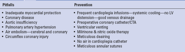
 COMPLICATIONS AND SOLUTIONS
Tables 18.5 to 18.7 list some of the major pitfalls and preventative measures associated with either direct vision, videoscopic, and robot-assisted MIMVS. Traditional mitral valve repair and replacement complications are also possible with MIMVS. These include inferior valve repairs, which have been shown to be dependent on individual surgeon experience and institutional clinical volume. Complications specific to MIMVS are often related to peripheral CPB cannulation/perfusion, aortic occlusion, and myocardial protection techniques. Some reports have shown the right lateral pericardial entry approach to be associated with increased phrenic nerve injuries (1%). In several clinical series the use of cold ventricular fibrillation has been implicated as a risk factor for adverse neurologic events; however, our series has shown this not to be a complicating factor. In a large meta-analysis Sunderman et al. showed similar results with minimally invasive mitral repair to the traditional sternotomy approach. The careful analysis of Modi et al. suggested that in patients carefully screened for peripheral vascular disease, the stroke risk with retrograde perfusion is no higher than with antegrade inflow.
TABLE 18.5 Perfusion and Aortic Clamping: Pitfalls and Prevention

In our early series, we performed over 600 minimally invasive nonrobotic videoscopic mitral valve repairs and replacements with an overall operative mortality of 0.2%. Our last published report detailed 540 consecutive robotic mitral repair patients with 86 undergoing a concomitant cryo-MAZE to ablate atrial fibrillation. The 30-day mortality was 0.2% for an isolated mitral repair and 3.6% for a replacement. Between May 2000 and July 2014, the author performed 906 robotic mitral valve repairs with 231 of repairs having a concomitant cryomaze procedure. Of these patients 98% had degenerative pathology with a 100% repair rate for these. Degenerative mitral valve pathology was protean and patients required both simple and complex mitral reconstructions. Our repair “toolbox” included, among others, leaflet sliding plasties, leaflet folding plasties, neochord replacements, chordal transfers, papillary muscle shortening, and cleft closures as well as band annuloplasties (Table 18.4). Immediately after the repair, 98% of patients had either no or trace mitral regurgitation by TEE. For the entire robot-assisted mitral repair series, the overall 30-day mortality was 1.3%, but for patients having a repair alone was 0.25%. Follow-up of the 906 patients revealed a 2.9% overall failure rate requiring a reoperation. Others have reported similar mortality, morbidity, and repair quality in addition to decreased perfusion and cross-clamp times. Thus, today large-volume reference centers have shown that robotic mitral valve surgery is safe, efficacious, and can provide excellent repair results as well as other patient benefits.
TABLE 18.6 Pulmonary: Pitfalls and Prevention
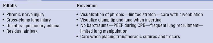
TABLE 18.7 Ventricular Dysfunction: Pitfalls and Prevention
Carpentier A, Adams DH, Filsoufi F. Carpentier’s reconstructive valve surgery. Maryland Heights, MO: Saunders Elsevier; 2010: 1–353.
Chitwood WR Jr. Atlas of robotic cardiac surgery. London: Springer, 2014:1–326.
Chu MW, Gersch KA, Rodriguez E, et al. Robotic “haircut” mitral repair: Posterior leaflet-plasty. Ann Thorac Surg. 2008;85:1460–1462.
Cohn LH, Adams DH, Couper GS, et al. Minimally invasive cardiac valve surgery improves patient satisfaction while reducing costs of cardiac valve replacement and repair. Ann Surg. 1997;226:421–426; discussion 427–428.
Cosgrove DM 3rd, Sabik JF, Navia JL. Minimally invasive valve operations. Ann Thorac Surg. 1998;65:1535–1538.
Falk V, Cheng DC, Martin J, et al. Minimally invasive versus open mitral valve surgery: A consensus statement of the international society of minimally invasive coronary surgery (ISMICS) 2010. Innovations (Phila.) 2011;6:66–76.
Falk V, Seeburger J, Czescia M, et al. How does the use of polytetrafluoroethylene neochordae for posterior mitral valve prolapse (loop technique) compare with leaflet resection? A prospective randomized trial. J Thorac Cardiovasc Surg. 2008;136(5):1205–1206.
Galloway AC, Schwartz CF, Ribakove GH, et al. A decade of minimally invasive mitral repair: Long-term outcomes. Ann Thorac Surg. 2009;88:1180–1184.
Gammie JS, Zhao Y, Peterson ED, et al. J. Maxwell Chamberlain Memorial Paper for adult cardiac surgery. Less-invasive mitral valve operations: trends and outcomes from the society of thoracic surgeons adult cardiac surgery database. Ann Thorac Surg. 2010;90:1401–1408.
Iribarne A, Easterwood R, Russo MJ, et al. Comparative effectiveness of minimally invasive versus traditional sternotomy mitral valve surgery in elderly patients. J Thorac Cardiovasc Surg. 2012; 143:S86–S90.
Mihalijevic T, Jarrett CM, Gillinov AM, et al. A novel running annuloplasty suture technique for robotically assisted mitral valve repair. J Thorac Cardiovasc Surg. 2010;139:1343–1344.
Mihaljevic T, Jarrett CM, Gillinov AM, et al. Robotic repair of posterior mitral valve prolapse versus conventional approaches: Potential realized. J Thorac Cardiovasc Surg. 2011;141:72–80.
Mihaljevic T, Koprivanac M, Kelava M, et al. Value of robotically assisted surgery for mitral valve disease. JAMA Surg. 2014; 149:679–686.
Modi P, Chitwood WR Jr. Retrograde femoral arterial perfusion and stroke risk during minimally invasive mitral valve surgery: is there cause for concern? Ann Cardiothorac Surg. 2013;2:E1.
Modi P, Hassan A, Chitwood WR Jr. Minimally invasive mitral valve surgery: A systematic review and meta-analysis. Eur J Cardiothorac Surg. 2008;34:943–952.
Modi P, Rodriguez E, Hargrove WC 3rd, et al. Minimally invasive video-assisted mitral valve surgery: A 12-year, 2-center experience in 1178 patients. J Thorac Cardiovasc Surg. 2009;137:1481–1487.
Murphy DA, Miller JS, Langford DA, et al. Endoscopic robotic mitral valve surgery. J Thorac Cardiovasc Surg. 2006;132:776–781.
Navia JL, Cosgrove DM 3rd. Minimally invasive mitral valve operations. Ann Thorac Surg. 1996;62:1542–1544.
Nifong LW, Rodriguez E, Chitwood WR. 540 Consecutive robotic mitral valve repairs including concomitant atrial fibrillation cryoablation. Ann Thorac Surg. 2012;94:38–42.
Nishimura RA, Otto CM, Bonow RO, et al. 2014 AHA/ACC guideline for the management of patients with valvular heart disease: executive summary: A report of the American college of cardiology/American heart association task force on practice guidelines. J Am Coll Cardiol. 2014;63:2438–2488 and Circulation. 2014;129:2440–2492.
Sunderman SH, Sromicki J, Rodriguez Cetina Biefer H, et al. Mitral valve surgery: Right lateral mini-thoracotomy or sternotomy? A systematic review and meta-analysis. J Thorac Cardiovasc Surg. 2014;148(5):1989–1995.
Suri RM, Burkhart HM, Daly RC, et al. Robotic mitral valve repair for all prolapse subsets using techniques identical to open valvuloplasty: establishing the benchmark against which percutaneous interventions should be judged. J Thorac Cardiovasc Surg. 2011;142:970–979.
Suri RM, Schaff HV, Meyer SR, et al. Thoracoscopic versus open mitral valve repair: A propensity score analysis of early outcomes. Ann Thorac Surg. 2009;88:1185–1190.
Suri RM, Thompson JE, Burkhart HM, et al., Improving affordability through innovation in the surgical treatment of mitral valve disease. Mayo Clin Proc. 2013;88:1075–1084.
Svensson LG, Atik FA, Cosgrove DM, et al. Minimally invasive versus conventional mitral valve surgery: A propensity-matched comparison. J Thorac Cardiovasc Surg. 2010;139:926–932.
Vahanian A, Alfieri O, Andreotti F; Joint Task Force on the Management of Valvular Heart Disease of the European Society of Cardiology (ESC); European Association for Cardio-Thoracic Surgery (EACTS). Guidelines on the management of valvular heart disease (version 2012). Eur Heart J. 2012;33:2451–2496.