Chapter 1
Navigating the User Interface
If you’re new to the AutoCAD® Civil 3D® software environment, then your first experience has probably been a lot like staring at the instrument panel of an airplane. Civil 3D can be quite intimidating, with lots of buttons, strange shapes, and unusual icons—all packed into a relatively small area. In addition, you may be even more intimidated by the feeling that there is a lot of power under the hood.
This leads us to our main objective for this chapter, which is to alleviate that feeling of intimidation and make you feel much more at ease within the Civil 3D environment. Let me start you down that path by saying that there’s a big difference between an airplane and Civil 3D. In Civil 3D, if you really mess up, you can simply close the drawing file without saving. When piloting an airplane, it’s a little more difficult to undo your mistakes.
After completing this chapter, you will have achieved a greater comfort level within the Civil 3D environment by being able to identify the main user interface components and utilize them for basic functions. You will also be able to use two specific features that will serve you well throughout the program: the Transparent Commands toolbar and the Inquiry Tool.
In this chapter, you’ll learn to
- Navigate the Civil 3D user interface
- Launch general commands through the application menu
- Launch key software commands and functions using the ribbon
- Navigate the design contents using the Toolspace
- Navigate the model using the drawing area
- Communicate with Civil 3D using the command line
- Access and modify design information using Panorama
- Access specialized commands using the Transparent Commands toolbar
- Get information about your design using the Inquiry Tool
Getting to Know the Civil 3D User Interface

To begin learning about the Civil 3D environment, let’s take our airplane analogy down a notch and think about this as learning to drive an automobile. When your parents first sat you down at the wheel and talked about the car’s controls, they probably didn’t mention the air conditioning or the radio. Those, of course, are important parts of the driving experience, but I’m betting they started with the most important parts, such as the steering wheel, gas pedal, and, most important of all, brake pedal. We’re going to approach your first experience with “driving” Civil 3D in much the same manner.
There are many, many parts to the Civil 3D user interface. For the purpose of this book, I’ll cover just the ones that will be most important in enabling you to navigate the software effectively. Figure 1-1 shows the major components of the user interface:
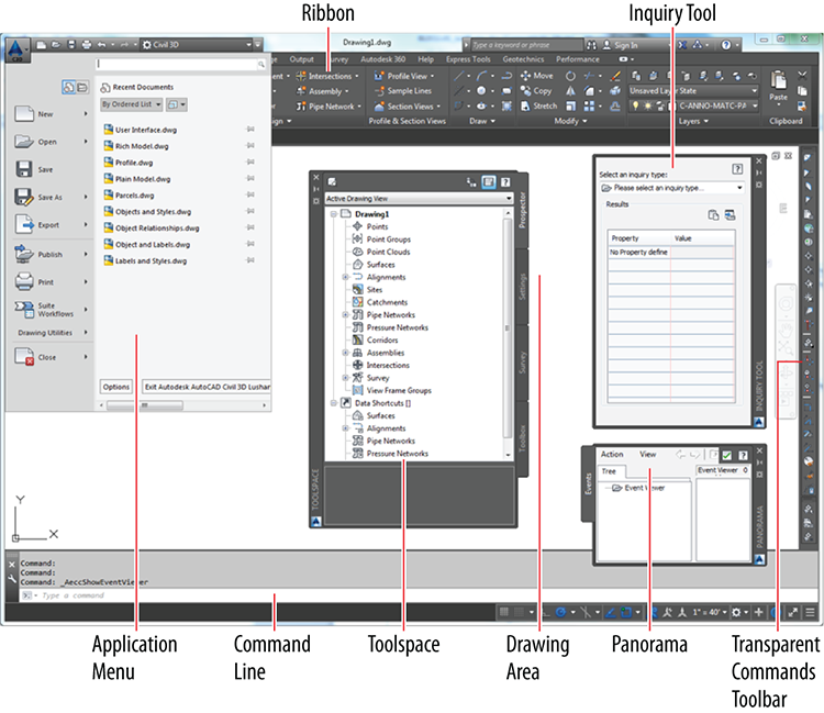
Figure 1-1: Major components of the Civil 3D user interface
- Application Menu The place where you can find everyday file-handling commands that enable you to do things like open, save, and print your drawings
- Ribbon The place where most Civil 3D commands are launched
- Toolspace The Civil 3D “command center” where all the data and settings are laid out in an organized fashion
- Drawing Area The place where the drawing is created
- Command Line The “chat window” where you and Civil 3D talk to one another
- Panorama A multipurpose window where you can view and/or edit drawing information and properties
- Inquiry Tool A tool with many smaller tools within it that enable you to get information about your design
- Transparent Commands Toolbar A toolbar with special commands that allow drafting and geometric construction to be done in the way that civil engineers and surveyors do it
Working with the Application Menu
The application menu (see Figure 1-2) expands out from the square AutoCAD Civil 3D icon located at the top left of your screen. Here, you’ll find commands for creating, opening, saving, and printing your drawing files.
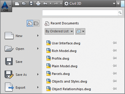
Figure 1-2: Part of the Civil 3D application menu
Exercise 1.1: Use the Application Menu to Open a File
In this exercise, you will use the application menu to open a file.
If you haven’t already done so, go to the book’s web page at www.sybex.com/go/civil3d2015essentials and download the files for Chapter 1. Unzip the files to the correct location on your hard drive according to the instructions in the introduction. Then, follow these steps:
- Launch Civil 3D by double-clicking the Civil 3D 2015 Imperial (Metric) icon on the desktop of your computer.
- On the New Tab, under Get Started, click Start Drawing.
This will create a new drawing tab named Drawing1.
- Click the application menu icon. Click Open, and then click Drawing.

- Browse to the
Chapter 01class data folder, and openUser Interface.dwg. - Open the application menu once more, and investigate the commands that are listed there. You’ll notice that most of them have to do with creating, opening, saving, and printing drawing files.
- Keep this drawing open for the next exercise.
Because nothing changes in this drawing file as a result of the exercise steps, no User Interface – Complete file is necessary.
Working with the Ribbon
The ribbon is located at the top of your screen, and it is the launching pad for most of your Civil 3D commands. The commands that it contains are organized into groups through the use of tabs and panels. The ribbon itself is divided into a series of tabs that include Home, Insert, Annotate, and so on, as illustrated in Figure 1-3.

Figure 1-3: Tabs arrange large numbers of similar Civil 3D commands into groups.
Each tab is divided into panels. For instance, the Home tab shown in Figure 1-4 includes the Palettes, Create Ground Data, Create Design, Profile & Section Views, and Draw panels.

Figure 1-4: Panels provide another level of grouping within a ribbon tab.
Because Civil 3D groups the commands in this way, you never have to choose from more than a handful of commands once you’ve taken your best guess at the correct tab and panel. Also, you’ll find that the more you use Civil 3D, the better you will get at knowing the location of the commands. It’s not so much memorizing their positions as it is learning how Civil 3D “thinks”—that is, the way in which it relates commands to one another and categorizes them into tabs and panels.
One other thing you should know is that most panels expand downward to show you the less frequently used commands in a particular category. You’ll know that a panel expands when you see a downward-pointing white triangle next to its name. For example, Figure 1-5 shows the Home tab’s Create Design panel expanded with more commands. Don’t forget to look on these hidden panels when searching for commands.
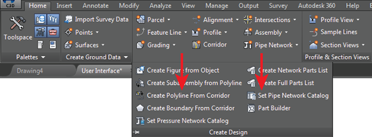
Figure 1-5: Most panels expand downward to reveal more commands, as is the case with the Create Design panel on the Home tab of the ribbon.
One of the best features of the ribbon is its ability to respond to what you select in the drawing area. For example, if you click a Civil 3D alignment, the ribbon changes and serves up alignment-related commands on a special tab. The same is true for surfaces, parcels, and so on. These special tabs are referred to as contextual ribbon tabs. They are a huge help when you’re first learning Civil 3D and a huge time-saver even after you’ve become a master.
Exercise 1.2: Use the Ribbon to Launch Commands
In this exercise, you will familiarize yourself with the ribbon’s tabs and panels.
If you have continued from the previous exercise, you can skip to step 2. Otherwise, if you haven’t already done so, go to the book’s web page at www.sybex.com/go/civil3d2015essentials and download the files for Chapter 1. Unzip the files to the correct location on your hard drive according to the instructions in the introduction. Then, follow these steps:
- Launch Civil 3D 2015, and open the file named
User Interface.dwg. - Click the Home tab of the ribbon to bring it to the forefront (it may be there already).
- Click the downward-pointing white triangle at the bottom of the Create Design panel and note how it expands down, as shown in Figure 1-5.
- Click the Insert tab of the ribbon. Here, you see words like insert, import, and attach, which are all ways of bringing information into the drawing.
- Click the other tabs of the ribbon, and see whether you can relate some of the words you see in the commands to the title of each ribbon tab.
- Place your cursor in the left viewport, and roll the mouse wheel forward to zoom in to the drawing. Keep zooming in until you can clearly see the road centerlines labeled with stationing numbers (these are Civil 3D alignments). Click one of the road centerlines, and note that the ribbon displays a contextual tab to make alignment commands accessible (see Figure 1-6).
- Keep this drawing open for the next exercise.
Because nothing changes in this drawing file as a result of the exercise steps, no User Interface – Complete file is necessary.
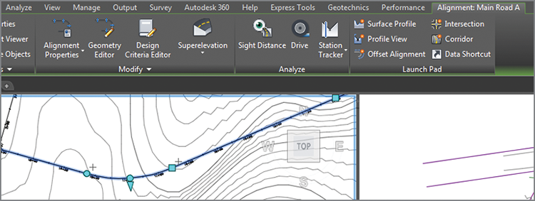
Figure 1-6: The ribbon displays the contextual Alignment: Main Road A tab because an alignment has been selected in the drawing (the name of the tab you see may be slightly different depending on which alignment you selected).
Working with the Toolspace
Think of the Toolspace as the Civil 3D “command center” where all Civil 3D data and settings are laid out in a nice, orderly arrangement. It has several main functions that are represented by the different tabs it can contain. Altogether, the Toolspace can house four tabs: Prospector, Settings, Survey, and Toolbox.
Prospector Tab
Prospector is arguably the most important part of the Civil 3D user interface. As you build your design, Prospector arranges the different components of your design in a tree structure (see Figure 1-7). Why a tree structure and not just a list of items? Later in this book, you’ll study how Civil 3D creates relationships between different parts of your design. In some ways, this tree structure helps represent some of those relationships as a hierarchy. Another, more practical reason for a tree structure is that it’s an efficient way to show a long list of items in a relatively small area—the branches of the tree can be collapsed to make room to expand other branches.
Another way to think about Prospector is that it arranges your design categorically rather than spatially. In other words, in your drawing area, you might see road centerlines crossing through parcels, which cross through contours, which cross through survey points. Everything is in the right place spatially, but from an organizational standpoint, it’s kind of a mess. Prospector sorts out this mess and puts all the points in one place, all the parcels in one place, and so on. Prospector also knows exactly where those objects are in the drawing. You can right-click an object in Prospector and use the Select command or Zoom To command to locate that object within the drawing.
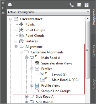
Figure 1-7: The Prospector tab with a portion of the tree structure highlighted in red
Exercise 1.3: Explore the Model with the Prospector Tab
In this exercise you will use the Prospector tab of the Toolspace to explore the model.
If you have continued from the previous exercise, you can skip to step 2. Otherwise, if you haven’t already done so, go to the book’s web page at www.sybex.com/go/civil3d2015essentials and download the files for Chapter 1. Unzip the files to the correct location on your hard drive according to the instructions in the introduction. Then, follow these steps:
- Launch Civil 3D 2015, and open the file named
User Interface.dwg. - If the Toolspace is not already open, click Toolspace on the Home tab of the ribbon.

- Click the Prospector tab of the Toolspace to bring it to the forefront.
- Explore the tree structure of Prospector by clicking the plus signs to expand the different branches.
- Expand Alignments ⇒ Centerline Alignments ⇒ Main Road A ⇒ Profiles. This hierarchical arrangement provides effective organization and suggests a relationship between the alignment and its profiles.
- Click within the left viewport to activate it. Then, on the Prospector tab, right-click Side Road B, and select Zoom To. Notice how Prospector knows the location of the alignment named Side Road B, even if you don’t.
- Keep this drawing open for the next exercise.
Because nothing changes in this drawing file as a result of the exercise steps, no User Interface – Complete file is necessary.
It’s important to point out that Prospector isn’t just a place for viewing your design; it’s also a place where you can change the appearance of your design, create new components for your design, edit your design, and so on. These types of functions are accessed through contextual menus such as the one used in step 6 of the previous exercise. A good rule of thumb when using Prospector is, “When in doubt, right-click it.”
Settings Tab
Civil 3D has a lot of settings that control nearly every aspect of how the software behaves. In fact, one of the things that makes Civil 3D so powerful is that you can customize its settings to accommodate nearly any type of design, any company standard, or any other factor that defines the environment within which you use it. The Settings tab is where these settings are managed; however, you won’t be spending much time here in the early part of your Civil 3D career. This area is more often the territory of a CAD manager or Civil 3D guru.
Exercise 1.4: Explore the Drawing Settings with the Settings Tab
In this exercise, you will use the Settings tab of the Toolspace to explore the drawing settings.
If you have continued from the previous exercise, you can skip to step 2. Otherwise, if you haven’t already done so, go to the book’s web page at www.sybex.com/go/civil3d2015essentials and download the files for Chapter 1. Unzip the files to the correct location on your hard drive according to the instructions in the introduction. Then, follow these steps:
- Launch Civil 3D 2015, and open the file named
User Interface.dwg. - If the Toolspace is not already open, click Toolspace on the Home tab of the ribbon.

- Click the Settings tab of the Toolspace.
- Expand Surface ⇒ Surface Styles, and note the list of styles shown there. These styles control the appearance of models that represent the shape of the ground.
- Expand Surface ⇒ Label Styles ⇒ Contour, and note the list of styles shown there. These styles control a certain type of label that is used to annotate surface models.
- Keep this drawing open for the next exercise.
Because nothing changes in this drawing file as a result of the exercise steps, no User Interface – Complete file is necessary.
Survey Tab
The Survey tab is specifically designed for working with survey data. You could call it “Prospector for surveyors” because it serves the same functions and works in much the same way as the Prospector tab. It displays survey data in a tree structure, and it allows you to launch commands through contextual menus.
Toolbox Tab
As if Civil 3D didn’t have enough stuff packed into it already, the Toolbox is a place where other add-ons can be plugged in. Your company may have some custom programming that is designed to run in Civil 3D, or some add-on modules provided by Autodesk. This is the place where you can load and run these additional enhancements to Civil 3D.
Using the Drawing Area
The drawing area is where you can actually see and “touch” the design model you are creating. The design model is most often viewed from above, referred to as plan view, but it can be viewed from any perspective. For example, because Civil 3D specializes in representing designs as 3D models, you may want to display your model using a 3D view. Figure 1-8 shows a model in both plan and 3D views.
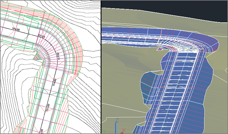
Figure 1-8: The drawing area showing the same model in plan view on the left and 3D view on the right
Using the Command Line
Think of the command line (see Figure 1-9) as a “chat window” where you talk with Civil 3D. Nearly everything you do is reported on the command line along with the response from Civil 3D. A response can be a request for more information, report of a result, or notification of a problem. It’s good to get into the habit of always watching the command line, because it often tells you what to do next. You can also launch commands from the command line, but you will likely find it much easier to use the visual interface provided by the ribbon and other tools.
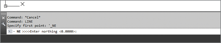
Figure 1-9: A view of the command line while a transparent command (covered later in this chapter) is used to draw a line. Notice how the command line reports that the LINE command has been started and then prompts for the first piece of information: the “first point.”
Using Panorama
Panorama is a multipurpose window that is used to show and/or modify many different types of information. It works by displaying a tab for the information that you or the program has called for. For example, the Events tab (also known as the Event Viewer) shows up when Civil 3D needs to tell you something about the drawing. In another example, if you launch the command to edit the geometric details of an alignment, the Alignment Entities tab appears. As shown in Figure 1-10, while Panorama displays information for one task, it also displays tabs for other tasks that you can access with a single click. This enables you to multitask within the same window.
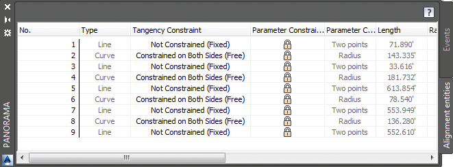
Figure 1-10: Panorama showing the Events and Alignment Entities tabs
Exercise 1.5: Explore Panorama
In this exercise, you will open the Event Viewer and Volumes Dashboard to become familiar with the Panorama.
If you have continued from the previous exercise, you can skip to step 2. Otherwise, if you haven’t already done so, go to the book’s web page at www.sybex.com/go/civil3d2015essentials and download the files for Chapter 1. Unzip the files to the correct location on your hard drive according to the instructions in the introduction. Then, follow these steps:
- Launch Civil 3D 2015, and open the file named
User Interface.dwg. - On the Home tab of the ribbon, expand the Palettes panel and click the icon for Event Viewer.

- Experiment with resizing, auto-hiding, and docking the Panorama window. You’ll find that it behaves much like other dockable windows in Civil 3D.
- Press Esc to clear any selections in the drawing. Click one of the contour lines in the drawing to display the Tin Surface: Existing Ground ribbon tab, and then click Volumes Dashboard on the Analyze panel.

- Close Panorama, and close the drawing without saving.
Because nothing changes in this drawing file as a result of the exercise steps, no User Interface – Complete file is necessary.
Using the Transparent Commands Toolbar
As you may already know, civil engineers and surveyors draw things a little differently than architects or mechanical engineers. They use things such as bearings, curve deltas, northings, and eastings to define geometry. The Transparent Commands toolbar enables Civil 3D users to draw things based on the special geometric concepts that are unique to civil engineers and surveyors.
For example, when drawing a line, you can use the Northing Easting transparent command to specify the first point and the Bearing Distance transparent command to specify the endpoint (see Figure 1-11).
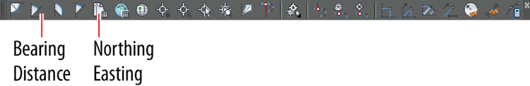
Figure 1-11: The Transparent Commands toolbar with red lines pointing to the Bearing Distance and Northing Easting transparent commands
Exercise 1.6: Use Transparent Commands to Draw Like a Civil Engineer
In this exercise, you will use one of the Transparent Commands to draw a line by bearing and distance.
If you haven’t already done so, go to the book’s web page at www.sybex.com/go/civil3d2015essentials and download the files for Chapter 1. Unzip the files to the correct location on your hard drive according to the instructions in the introduction. Then, follow these steps:
- Launch Civil 3D 2015, and open the file named
Line By Bearing.dwg. - Click the
Type a commandprompt on the command line. TypeLINE, and press Enter. - When prompted to specify the first point, click a point near the center of the screen.
- When prompted to specify the next point, click Bearing Distance on the Transparent Commands toolbar. Refer to Figure 1-11 for the location of this command.

- When prompted for a quadrant, either type
1and press Enter or click in the upper-right quadrant created by the crosshairs on the screen. - When prompted for the bearing, type
45and press Enter. - When prompted for the distance, type
500(150) and press Enter. Press Esc twice to exit the command. You have just drawn a line that is 500 feet (150 meters) long at a bearing of N 45° E. - Save and close the drawing.
To view the results of completing the exercise successfully, you can open Line By Bearing - Complete.dwg.
Using the Inquiry Tool
Most of the time, you’ll be the one providing the information for a drawing. Sometimes, however, you need your drawing to tell you something. That’s where the Inquiry Tool comes in. The Inquiry Tool is a separate window whose sole purpose is to give you information about things in the drawing. There is a long list of drawing items from which to choose, and beneath each item is a list of things that you can ask about (see Figure 1-12).
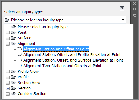
Figure 1-12: The Inquiry Tool showing a partial list of available inquiry types
Exercise 1.7: Use the Inquiry Tool to Answer Questions
In this exercise, you will use the Inquiry Tool to analyze the line that was drawn in the previous exercise.
If you haven’t already done so, go to the book’s web page at www.sybex.com/go/civil3d2015essentials and download the files for Chapter 1. Unzip the files to the correct location on your hard drive according to the instructions in the introduction. Then, follow these steps:
- Launch Civil 3D 2015, and open the file named
Inquiry.dwg. - On the Analyze tab of the ribbon, click the Inquiry Tool.

- Under Select An Inquiry Type, select Point ⇒ Point Inverse.
- When prompted to specify the first point, hold down the Shift key, right-click, and select Endpoint on the contextual menu that appears.
- Click the southwestern endpoint of the line you drew earlier.
- Use the Shift+right-click combination again to select Endpoint, and then click the opposite end of the line for the second point.
- Scroll down to the Direction and Horizontal Distance values in the Inquiry Tool window. Note that they show the same bearing and distance that you entered earlier.
Because nothing has changed in this drawing file, no Inquiry – Complete file is available.