Chapter 6
Displaying and Annotating Alignments
As you’ll find with nearly every design component you create for a land-development project, creating the design is only half the job. Alignments serve as the basis for further design of a linear feature, but they also serve as a means of expressing the geometry of the feature to reviewers and contractors. The alignment by itself doesn’t tell this story in enough detail and must therefore be stylized and annotated appropriately. In addition, alignments often serve as baselines used to express the location of other features within the project.
In this chapter, you’ll learn how to use various styles and annotations to convey important information about alignments.
In this chapter, you’ll learn to
- Apply alignment styles
- Apply alignment labels and label sets
- Create station/offset labels
- Create segment labels
- Apply tag labels and tables
Using Alignment Styles

As with other styles you have learned about, alignment styles are, as their name implies, used to control the appearance and behavior of alignments. By applying different styles, you can graphically distinguish between existing centerlines, proposed centerlines, and so on. You can even use styles to display alignments as something completely different, such as a property line or even a utility line. Figure 6-1 illustrates how styles enable alignments to represent many different things.
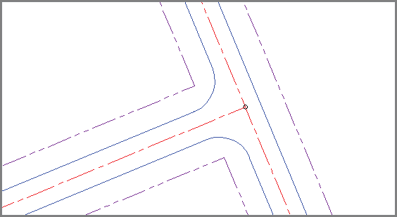
Figure 6-1: Different alignment styles are used to represent the right-of-way, edges of pavement, and centerlines in this drawing.
Alignment styles have two major ways of affecting the appearance of alignments. First, they control which components of the alignment are visible; and second, they control the graphical properties such as layer, color, and linetype of the components that are displayed.
Exercise 6.1: Apply Alignment Styles
In this exercise, you’ll use alignment styles to control the appearance of alignments.
If you haven’t already done so, go to the book’s web page at www.sybex.com/go/civil3d2015essentials and download the files for Chapter 6. Unzip the files to the correct location on your hard drive according to the instructions in the introduction. Then, follow these steps:
- Open the drawing named
Alignment Styles.dwglocated in theChapter 06class data folder.The drawing contains a dozen different alignments that are intended to serve different purposes. Currently, all the alignments look the same because they have been assigned a style of Standard.
- Select the alignment representing the centerline of Emerson Road, right-click, and select Properties.
- Change the style to C-ROAD-CNTR-E, as shown in Figure 6-2.
- Press Esc to clear the selection of the alignment. Select the Jordan Court centerline alignment, and change its style to C-ROAD-CNTR.
This displays this alignment as a simple series of lines and curves on the proposed road centerline layer.
- Change the style of the Jordan Court centerline alignment to C-ROAD-CNTR With Markers.
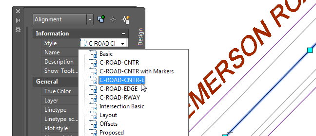
Figure 6-2: Assigning an alignment style in the Properties window
With this style, markers are placed at the beginning, end, points of curvature (PCs), points of tangency (PTs), points of reverse curvature (PRCs), and points of intersection (PIs). In addition, line extensions are displayed with the tangents extending to the PI markers. You would use this style for the polished look of a final plan but probably not for design.
- Change the style of the Madison Lane centerline alignment to Layout.
- For the alignments that run parallel to the Jordan Court centerline and extend the full length of the centerline, assign the C-ROAD-RWAY style.
This displays the alignments on the right-of-way layer, enabling them to take on the appearance of property lines.
- For the remaining alignments that represent the edges of pavement, change the style to C-ROAD-EDGE.
This displays the alignments on the edge-of-pavement layer.
- 9. Save and close the drawing.
You can view the results of successfully completing this exercise by opening Alignment Styles - Complete.dwg.
Applying Alignment Labels and Label Sets
Alignments (and, as you’ll learn later, profiles) have a special kind of annotation that is applied either to the entire alignment at once or to a range of stations within the alignment. This annotation repeats at specified increments or when specific types of geometry are encountered. This type of annotation is very useful because it changes as the alignment changes, even if new geometry is added or the length of the alignment changes. In all, you can add seven types of alignment labels in this way. This chapter doesn’t cover all seven types, but you’ll learn about the following three alignment label types:
- Major Station Labels Placed at the major station increment, which is larger than the minor station increment. They typically include a tick mark along with a numerical label calling out the station.
- Minor Station Labels Placed at the minor station increment, which is smaller than the major station increment. These typically consist of tick marks.
- Geometry Point Labels Placed at key geometric points along the alignment, such as the beginning of the alignment, ending of the alignment, places where there are curves, and so on.
Exercise 6.2: Apply Labels to Alignments
In this exercise, you’ll use the Add/Edit Station Labels command to add station labels, station ticks, and geometry labels to the Jordan Court alignment.
- Open the drawing named
Alignment Labels.dwglocated in theChapter 06class data folder. - Click the Jordan Court alignment. Then click Add Labels ⇒ Add/Edit Station Labels on the contextual ribbon tab.

- In the Alignment Labels dialog box, do the following:
- For Type, verify that Major Stations is selected.
- For Major Station Label Style, verify that Parallel With Tick is selected, then click Add.
- For Increment, enter 50 (20) to indicate the number of feet (meters) to increment, then click OK.
- Zoom in, and examine the labels that have been created.
Notice that a tick mark and label have been placed at 50-foot (20-meter) increments along the alignment.
- Click the Jordan Court alignment, and launch the Add/Edit Station Labels command as you did in step 2.

- In the Alignment Labels dialog box, do the following:
- For Type, select Minor Stations.
- For Minor Station Label Style, verify that Tick is selected, then click Add.
- Change Minor Station Increment to 10 (5) to indicate the number of feet (meters) to increment, then click OK.
- Examine the alignment once more.
Now you should see tick marks at 10-foot (5-meter) increments, which means there are four (three) minor tick marks between the major tick marks and labels.
- Launch the Add/Edit Station Labels command again, as you did in step 2. In the Alignment Labels dialog box, do the following:

- For Type, select Geometry Points.
- For Geometry Point Label Style, verify that Perpendicular With Tick And Line is selected, then click Add.
- In the Geometry Points dialog box, uncheck all boxes except Tangent-Curve Intersect, Curve-Tangent Intersect, and Reverse Curve-Curve Intersect.
- Click OK twice to dismiss the Geometry Points and Alignment Labels dialog boxes.
- Press Esc to clear the selection. Examine the alignment labels, and note the labels at the PCs, PTs, and PRC, as shown in Figure 6-3.
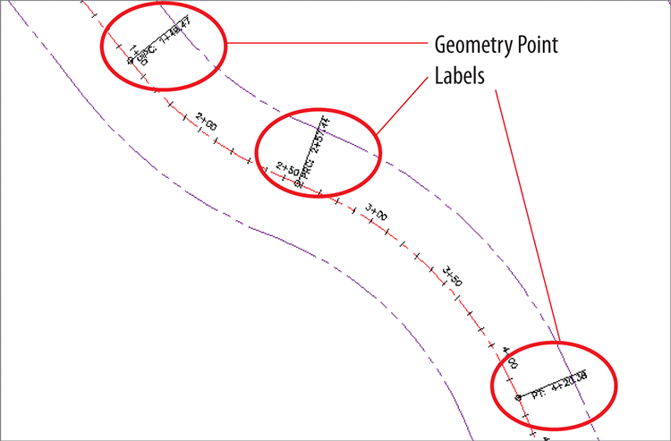
Figure 6-3: Geometry point labels displayed on the Jordan Court alignment
- Save and close the drawing.
You can view the results of successfully completing this exercise by opening Alignment Labels - Complete.dwg.
Using Alignment Label Sets
As you might guess, the collection of labels used in the previous exercise is quite common: station and tick at the major station, just a tick at the minor station, and labels calling out key geometric features. What if you could gather those three label types together in a nice, neat package and apply them all at once? That’s the exact purpose of a label set.
Exercise 6.3: Leverage Alignment Label Sets
In this exercise, you’ll use an alignment label set to capture the label configuration for Jordan Court and make it available for easy transfer to Madison Lane.
- Open the drawing named
Alignment Label Sets.dwglocated in theChapter 06class data folder. - Click the Jordan Court alignment. Then click Add Labels ⇒ Add/Edit Station Labels on the contextual tab of the ribbon.

- In the Alignment Labels dialog box, click Save Label Set.
- In the Alignment Label Set dialog box, on the Information tab, enter M50 Stations & m10 Ticks & Geometry Points (M20 Stations & m5 Ticks & Geometry Points) in the Name field.
- Click OK twice to close the Alignment Label Set dialog box and the Alignment Labels dialog box.
- Press Esc to clear the selection of the Jordan Court alignment. Click the Madison Lane alignment, and then click Add Labels ⇒ Add/Edit Station Labels on the contextual tab of the ribbon.

- In the Alignment Labels dialog box, click Import Label Set.
- Select M50 Stations & m10 Ticks & Geometry Points (M20 Stations & m5 Ticks & Geometry Points), and then click OK.
- Click OK to dismiss the Alignment Labels dialog box.
- Press Esc to clear the selection. Examine the Madison Lane alignment (see Figure 6-4), and note that the label set applied here is the same as the label set that was applied to Jordan Court.
- Save and close the drawing.
You can view the results of successfully completing this exercise by opening Alignment Label Sets - Complete.dwg.
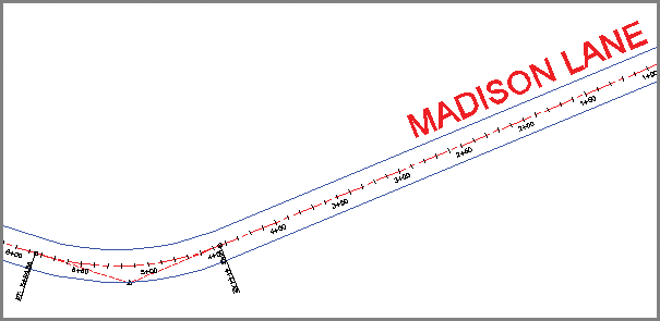
Figure 6-4: The Madison Lane alignment after the label set has been applied
Editing Alignment Labels
Working with alignment labels is a bit different than working with other labels because alignment labels exist in groups. If you click a major station label, for example, all the major station labels for the entire alignment will be selected. So, what if you want to change something about just one label? The answer is to use your Ctrl key when selecting individual labels in a group.
Another type of label edit that you’ll be introduced to in this chapter is flipping. Flipping a label simply means switching it over to the other side of the line.
Exercise 6.4: Edit Alignment Labels
In this exercise, you’ll edit the labels for Jordan Court such that the geometry labels are moved outside the right-of-way lines. You’ll also flip a geometry point label and grip-edit an individual station label to resolve a labeling conflict.
- Open the drawing named
Editing Alignment Labels.dwglocated in theChapter 06class data folder. - Click one of the geometry point labels on the Jordan Court alignment. Then click Edit Label Group on the contextual ribbon tab that appears.

- Click in the Style column to the right of Geometry Points. Select Perpendicular With Tick And Line – Offset, and click OK.
- Click OK to dismiss the Alignment Labels dialog box, and press Esc to clear the selection.
- While holding down the Ctrl key, click the first PC label, and then click Flip Label on the ribbon. The label is flipped to the opposite side of the road.

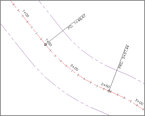
Figure 6-5: Changing the style of the geometry point labels improves their appearance and readability by moving them outside the right-of-way line.
- Zoom to the intersection of Madison Lane and Jordan Court.
- Click the 0+00 (0+000) station label of Madison Lane, and then click the square grip that appears above the label. Drag the grip to a clear area in the drawing.
The station label is more readable in its new location, and a leader appears that indicates the actual location of the station.
- Save and close the drawing.
You can view the results of successfully completing this exercise by opening AEditing Alignment Labels - Complete.dwg.
Creating Station/Offset Labels
As mentioned earlier, an alignment is often used as a baseline, enabling other features to express their locations in relation to that baseline. This is typically done with station offset notations, and, of course, the AutoCAD® Civil 3D® program provides you with labels to do just that. This type of label is referred to as a station/offset label.
Unlike the label groups you learned about earlier, station/offset labels stand alone and instead of being part of a set. They are capable of reporting the station and offset of a point that you select as well as the alignment name, coordinates of the point, and other types of information.
You can create station/offset labels as either fixed or floating labels. If they are fixed, then they hold their positions and update the station and offset values when the alignment is edited. If they are floating, then they maintain their station and offset values and move with the alignment when it’s edited. Like spot elevation labels, station/offset labels are paired with a marker.
Exercise 6.5: Create Station/Offset Labels
In this exercise, you’ll add station/offset labels to define the road geometry at the intersection of Jordan Court and Madison Lane.
- Open the drawing named
Station Offset Labels.dwglocated in theChapter 06class data folder. - Click the Jordan Court alignment, and then click Add Labels ⇒ Station/Offset – Fixed Point on the contextual ribbon tab.

- While holding down the Shift key, right-click and select Endpoint.
- Click the northern end of the northern arc. A new label that references the Jordan Court alignment is created at this location.
- While holding down the Shift key, right-click and select Endpoint. Then click the southern end of the southern arc.
- Press Esc twice to end the command and clear the selection of the alignment. Click the Madison Lane alignment, and then click Add Labels ⇒ Station/Offset – Fixed Point on the contextual ribbon tab.

- While holding down the Shift key, right-click and select Endpoint. Click the western end of the northern arc.
- While holding down the Shift key, right-click and select Endpoint. Then click the western end of the southern arc.
- Press Esc twice to end the labeling command and clear the selection of the alignment.
- Click one of the labels, and then click the square grip and drag it to a new location that is clear of other lines and text. Repeat this for the other labels to improve their appearance and readability.
The result should look similar to Figure 6-6.
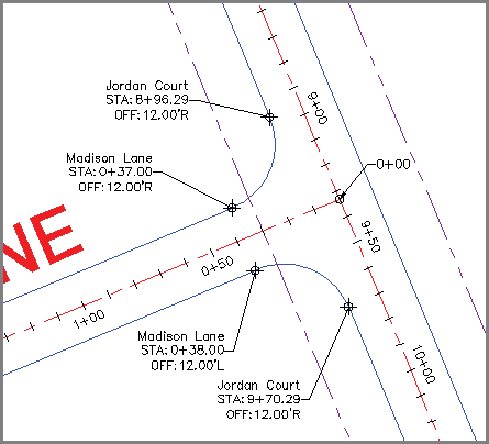
Figure 6-6: Station/offset labels applied to the edge-of-pavement arcs at the intersection of Madison Lane and Jordan Court
- Save and close the drawing.
You can view the results of successfully completing this exercise by opening Station Offset Labels - Complete.dwg.
Creating Segment Labels
So far, you have seen label groups that label the entire alignment at once and station/offset labels that are typically used to label something other than the alignment. What about the individual parts of the alignment? How do you tell reviewers and contractors how to re-create those alignments in the field? The answer is segment labels. Segment labels allow you to label things such as bearings and distances for tangents and curve data for curves. By providing this information as text in the drawing, you give viewers of the drawing the information they need to stake out the alignment in the field. You’re also sharing information about the geometric “performance” of the alignment that might answer questions such as these: Are the curves too sharp for the expected speed? Is the alignment parallel to other important features? Are intersecting roads perpendicular to one another?
Segment labels stand alone like station/offset labels; however, you can create them in bulk if you so desire. For example, all the tangents of an entire alignment can be labeled at once if you choose that option when creating the labels.
Exercise 6.6: Create Segment Labels
In this exercise, you’ll add segment labels to define bearing, distance, and curve information for the Madison Lane and Jordan Court alignments.
- Open the drawing named
Segment Labels.dwglocated in theChapter 06class data folder. - Click the Madison Lane alignment, and then click Add Labels ⇒ Add Alignment Labels.

- In the Add Labels dialog box, do the following:
- For Label Type, select Single Segment.
- For Line Label Style, verify that Bearing Over Distance is selected.
- For Curve Label Style, verify that Curve Data is selected, then click Add.
- Zoom in, and click one of the tangents of Madison Lane.
Notice the bearing and distance label that is created.
- Press Esc to end the labeling command. Click the newly created label, and then click Flip Label on the ribbon.
This swaps the position of the bearing and distance.

- Select the label again, and this time select Reverse Label.
- Click Add in the Add Labels dialog box. Then click the curve and the other tangent of Madison Lane to create two more labels in the drawing.
- Press Esc to end the labeling command. Click the curve label, and then click the label’s square grip and drag it to a clear location in the drawing.
- In the Add Labels dialog box, change Label Type to Multiple Segment. Change Curve Label Style back to Curve Data.
- Click Add, and then click anywhere on the Jordan Court alignment.
All tangents and curves are labeled at once.
- Move the curve labels for Jordan Court to open areas in the drawing so that they are easier to read (see Figure 6-7).
- Save and close the drawing.
You can view the results of successfully completing this exercise by opening Segment Labels - Complete.dwg.
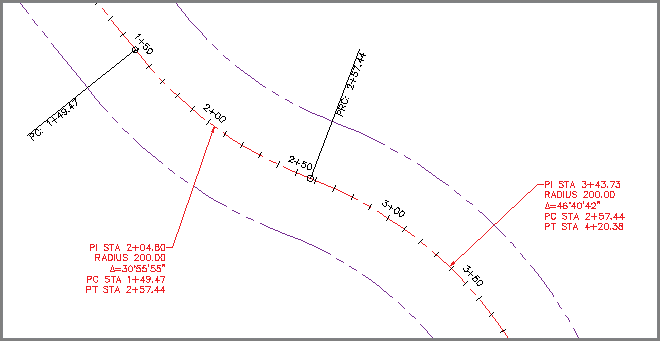
Figure 6-7: Curve labels added to the Jordan Court alignment. To improve readability, the labels have been dragged away from the alignment and into clear areas.
Using Tag Labels and Tables
Sometimes, it’s better to put all the geometric data for an alignment in a table rather than labeling it right on the alignment itself. This can clear up a cluttered drawing and provide space for other types of annotations. You can accomplish this in Civil 3D by using tag labels and tables.
A tag label is a special kind of label that assigns a number to a curve, tangent, or spiral. Common examples are C1, S1, and L1 for a curve, spiral, or tangent, respectively. Tag labels can be created ahead of time if you know you’re going to use a table, or you can convert regular labels to tag labels on-the-fly. In fact, you can convert just a few of the labels to tag labels and use a combination of a table and in-place labels to convey alignment information. This is common in cases where certain segments of an alignment are too short to have a label fit on them nicely.
As Murphy’s Law would have it, the numbers you get when creating tag labels are almost never what you want them to be. This is no fault of the software; in fact, the reason for this happening so frequently is that the software is doing its job. Each time you create a tag label, Civil 3D bumps the next tag number up by one. Because most designs are laid out and labeled more than once (lots more, in most cases), your next tag number is likely to be set to something other than 1.
Fortunately, Civil 3D is quite good at enabling you to correct your tag labels. There is even a Renumber Tags command designed for that specific purpose.
Exercise 6.7: Create Tag Labels
In this exercise, you’ll create and renumber tag labels for the Jordan Court alignment.
- Open the drawing named
Tag Labels.dwglocated in theChapter 06class data folder. - Click the Jordan Court alignment, and then click Add Labels ⇒ Add Alignment Labels on the contextual ribbon tab.

- In the Add Labels dialog box, select Multiple Segment as the label type.
- Verify that Circle Tag is selected for both Line Label Style and Curve Label Style.
- Click Add, and then click anywhere on the Jordan Court alignment. Press Esc to end the labeling command.
As you can see in Figure 6-8, curve and line tag labels have been created, but the numbering is not what it should be. You’ll address this in the next exercise.
- Open the drawing named
Renumber Tags.dwglocated in theChapter 06class data folder. - Click the Jordan Court alignment, and then select Renumber Tags on the contextual ribbon tab.

- On the command line, type
Sfor settings, and press Enter.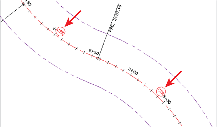
Figure 6-8: Curve tag labels on the Jordan Court alignment
- Change all values to 1 in the Table Tag Numbering dialog box, and click OK.
- Starting at the beginning of the Jordan Court alignment, click each tag label in order from start to end.
- Save and close the drawing.
You can view the results of successfully completing this exercise by opening Renumber Tag Labels - Complete.dwg.
Creating Tables
Once you have created all the tag labels and numbered them correctly, you’re ready to create a table. Civil 3D provides four types of alignment tables that you can insert into your drawing: line, curve, spiral, and segment. A segment table is a combination of the other three tables.
When you create a table in your drawing, you have full control over which data is included in it. You can choose to provide table data for the entire alignment, you can tell Civil 3D to seek out certain label styles and include them in your table, or you can handpick the labels from the drawing by selecting them directly.
As you’ll find with all Civil 3D tables, they are dynamically linked to the objects for which they display data. In the case of alignments, as the alignment is modified, the table updates automatically. There is even an option to create additional table entries as new tangents, curves, or spirals are created in the process of editing. Imagine how much time is saved by not having to go back and check all the numbers in a table each time an alignment is tweaked.
Exercise 6.8: Create a Table
In this exercise, you’ll create a table for the tag labels you created and renumbered in the previous exercise.
- Open the drawing named
Create Table.dwglocated in theChapter 06class data folder. - Click the Jordan Court alignment, and then click Add Tables ⇒ Add Segments on the contextual ribbon tab.

- In the Alignment Table Creation dialog box, click the Select By Label Or Style option.
- If you’re unable to read the label style names, click and drag the lower-right corner of the dialog box to increase its size. Then click and drag the line between the Label Style Name and Selection Rule column headings to widen the Label Style Name column. Repeat these actions as needed until you can see the full names of the label styles listed.
- Check the boxes in the Apply column for Alignment Curve: Circle Tag and Alignment Line: Circle Tag.
- Click OK. Click a point in an open area of the drawing to insert the table.
The table reflects the geometric data for the alignment (see Figure 6-9).
- Save and close the drawing.
You can view the results of successfully completing this exercise by opening Create Table - Complete.dwg.
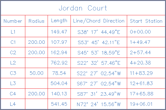
Figure 6-9: An alignment segment table for Jordan Court