Chapter 7
Designing Vertically Using Profiles
Now that the paths of the roads have been established as alignments representing their centerlines, we’ll look at the answers to these questions: What will it be like to travel along those paths? Will the terrain be steep or flat? Will it change much from one end of the road to the other? Will it require earth to be moved to smooth out the bumps in the road?
In Chapter 4, “Modeling the Existing Terrain Using Surfaces,” you learned how existing ground surfaces can be used to analyze the shape of the ground. Although surfaces can be quite effective for this purpose, you’re looking for something that tells you specifically what the terrain is like in relation to the road alignment. Once you have learned that, you’ll be looking for an effective way to redesign the terrain to create a nice, smooth road.
Whether you’re analyzing the terrain along an alignment or redesigning it, the tool that is most effective is the profile. Profiles allow you to show a slice through the ground along a specific alignment. This provides you with a clear and direct visualization of changes in terrain so that you can assess existing conditions and improve your design if necessary.
In this chapter, you’ll learn to
- Create surface profiles
- Display profiles in profile views
- Create design profiles
- Edit profiles
- Apply design check sets and criteria files
Creating Surface Profiles

One of the first steps in designing the vertical aspect of a linear feature is to analyze the shape of the existing terrain along that feature. You’ve learned how surfaces are used to create 3D models of the shape of the ground. You’ve also learned that there are many potential uses for surfaces other than displaying contours or labeling spot elevations. One of these uses is the creation of profiles from surface data, which helps with the design of linear features such as roads, channels, pipelines, and so on.
When a profile is created based on the data within a surface, it’s aptly named a surface profile. A surface profile maintains a dynamic link to the surface it references. In fact, a surface profile is tied to both the alignment and the surface used to create it. If either one changes, the surface profile is updated.
Exercise 7.1: Create a Surface Profile
In this exercise, you’ll create a surface profile along the Jordan Court alignment.
- Open the drawing named
Surface Profile.dwglocated in theChapter 07class data folder. - Click the Jordan Court alignment in the drawing, and then click Surface Profile on the contextual ribbon tab.

- In the Create Profile From Surface dialog box, verify that Jordan Court is selected as the alignment.
- Under Select Surfaces, select EG. Click Add, and then click OK.
- In Prospector, expand Alignments ⇒ Centerline Alignments ⇒ Jordan Court ⇒ Profiles. You should see EG – Surface (1) listed under Profiles.
- Right-click EG – Surface (1), and select Properties.
- On the Information tab of the Profile Properties dialog box, change Name to Jordan Court EGCL. Click OK.
Although Prospector shows you that a profile has been created, you have nothing graphical to view. To display a graphical representation of the profile in your drawing, you need a profile view, which takes us to the next section.
- Save and close the drawing.
You can view the results of successfully completing this exercise by opening Surface Profile - Complete.dwg.
Displaying Profiles in Profile Views
In the AutoCAD® Civil 3D® software, you must use a profile view to display a profile. A profile view is basically a grid that represents stations in the x direction and elevations in the y direction. The stations along the alignment and their corresponding elevations are plotted on this grid, and the resulting line represents changes in the terrain along the alignment. The profile view also includes various types of labels, such as axis labels and axis titles, to provide context to the display of the profile. Profile views can be further augmented with bands, which will be covered in Chapter 8, “Displaying and Annotating Profiles.”
Exercise 7.2: Create a Profile View
In this exercise, you’ll create a profile view to display the surface profile that you created in the previous exercise.
If you haven’t already done so, go to the book’s web page at www.sybex.com/go/civil3d2015essentials and download the files for Chapter 7. Unzip the files to the correct location on your hard drive according to the instructions in the introduction. Then, follow these steps:
- Open the drawing named
Profile View.dwglocated in theChapter 07class data folder. - Click the Jordan Court alignment, and then click Profile View on the contextual ribbon tab.

- In the Create Profile View – General dialog box, click Create Profile View.
- When prompted for the profile view origin, click a point in the open area to the east of the project.
A new profile view is inserted into the drawing, as shown in Figure 7-1.
- Save and close the drawing.
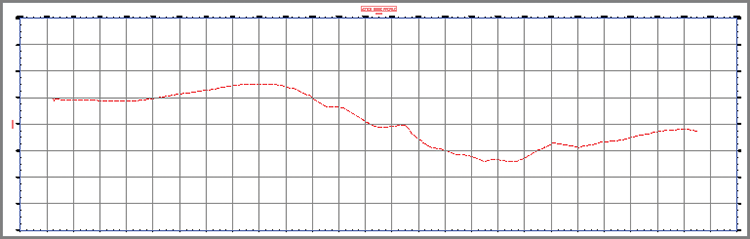
Figure 7-1: The newly created profile view
You can view the results of successfully completing this exercise by opening Profile View - Complete.dwg.
Now you have your first picture of the nature of the terrain along the Jordan Court alignment. As you study the profile, you see a relatively flat area at the beginning, a fairly steep drop into a low area, and then a gradual rise for the remaining third of the alignment. The appearance of the line is somewhat jagged, which indicates moderately rough terrain. In just a short time, you have created a graphical depiction of what it would be like to travel down the path of the road as it exists right now. From this image, you can begin to visualize the adjustments that will be needed to create a smooth and safe driving experience.
Creating Design Profiles
Earlier, you used a surface profile to determine the nature of the existing terrain along the path of Jordan Court. As the surface profile shows, the current state of this path isn’t suitable for driving, so it must be transformed into something with much more subtle geometry. In other words, a new profile must be designed for the road. In Civil 3D, this type of profile is often referred to as a design profile or layout profile.
Like alignments, design profiles consist of straight line segments (called tangents) and the curves that connect them. The curve geometry is a bit different, but essentially you can think of a design profile as an alignment turned on its side. The process of laying out a profile is very similar to laying out an alignment, right down to the Profile Layout Tools toolbar, which bears a striking resemblance to the Alignment Layout Tools toolbar.
Exercise 7.3: Design a Profile
In this exercise, you’ll create a design profile representing the finished ground centerline elevations for Jordan Court.
- Open the drawing named
Design Profile.dwglocated in theChapter 07class data folder. - Click one of the grid lines for the Jordan Court profile view, and then click Profile Creation Tools on the contextual ribbon.

- In the Create Profile – Draw New dialog box, enter Jordan Court FGCL for Profile Name.
- Verify that Profile Style is set to Design Profile and Profile Label set is set to _No Labels. Click OK.
- On the Profile Layout Tools toolbar, click the small black triangle on the far-left button to expand it, and then click Draw Tangents With Curves (see Figure 7-2).

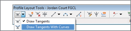
Figure 7-2: Invoking the Draw Tangents With Curves command
- Press and hold the Shift key, and then right-click. Click Osnap Settings at the bottom of the shortcut menu.
- In the Drafting Settings dialog box, uncheck all boxes except Object Snap On (F3) and Center. Click OK.
- Click the center of the circle marked A. Then click the remaining circles in order from left to right. Press Enter after clicking the circle marked G.
The newly created profile consists of a PVI at each point you clicked. Because you used the Draw Tangents With Curves command, all PVIs (except for the begin and end points) also include a vertical curve.
- Save and close the drawing.
You can view the results of successfully completing this exercise by opening
Design Profile - Complete.dwg.
Editing Profiles
As you learned in Chapter 5, “Designing in 2D Using Alignments,” it is common (and often recommended) to lay out a rough version of a design and then apply a series of refinements to achieve the final design. This is especially true with profiles because the first pass is usually an attempt to match existing ground as closely as possible without creating too many of your own bumps in the road. Why try to match existing ground? Quite simply, it’s cheaper. The closer your new road matches the existing terrain, the less earth will need to be moved to construct it. The cost of moving earth is measured by the volume of earth that is excavated, so less digging equals less cost.
After you create the initial profile that roughly matches existing ground, you must then refine the design based on various factors such as performance requirements for the road, avoiding overhead and underground obstacles, and ensuring that rainwater will drain properly. Many times, the adjustments you make are based not only on your own ideas but also on the input of others involved in the project. Whatever the case, a good set of tools for editing profiles is going to come in handy. Civil 3D provides a robust set of tools for editing profiles graphically and numerically.
Exercise 7.4: Edit a Profile with Grips
In yet another respect, profiles are similar to alignments in that they come equipped with specialized grips that enable editing to be done efficiently. In this exercise, you’ll use grips to edit the Jordan Court design profile.
- Open the drawing named
Graphical Editing.dwglocated in theChapter 07class data folder. - Click the blue Jordan Court FGCL profile to display its grips. Click the upright triangular grip located in the circle marked A1, and drag it to the center of the circle marked A2, as shown in Figure 7-3.
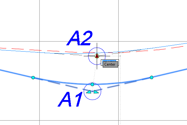
Figure 7-3: Moving a PVI grip
- At the circle marked B1, click the triangle grip on the right and drag it to the center of the circle marked B2, as shown in Figure 7-4.
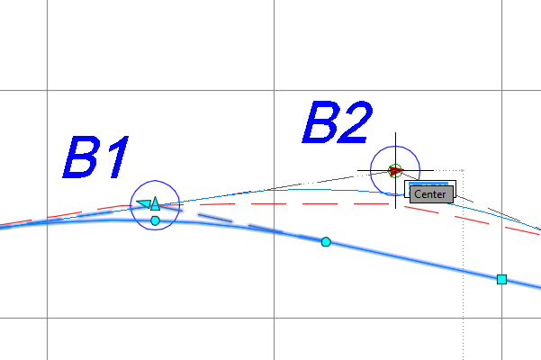
Figure 7-4: Moving a tangent slope grip
- Click the square grip at the center of circle C1, and move it to the center of circle C2, as shown in Figure 7-5.
- Click the circular grip located at the center of circle D1, and move it to the center of circle D2, as shown in Figure 7-6.
This is an example of moving the pass-through grip, forcing the curve to pass through a given point while adjusting the length of the curve.
- Click the circular grip at the center of circle E1, and move it to the center of circle E2, as shown in Figure 7-7.
This is an example of moving the endpoint grip of the curve, which also moves the start point to adjust the length of the curve.
- Save and close the drawing.
You can view the results of successfully completing this exercise by opening
Graphical Editing - Complete.dwg.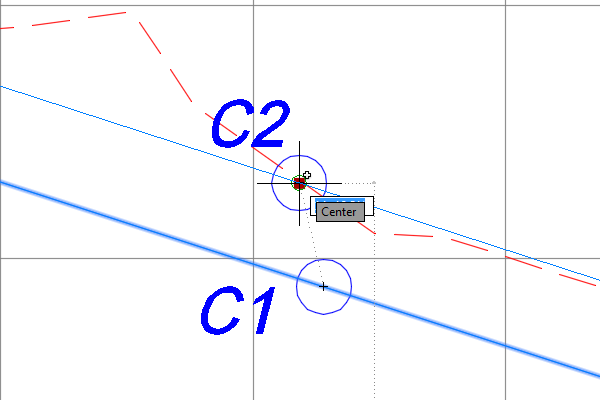
Figure 7-5: Moving a tangent midpoint grip
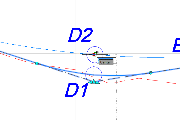
Figure 7-6: Moving the pass-through point grip
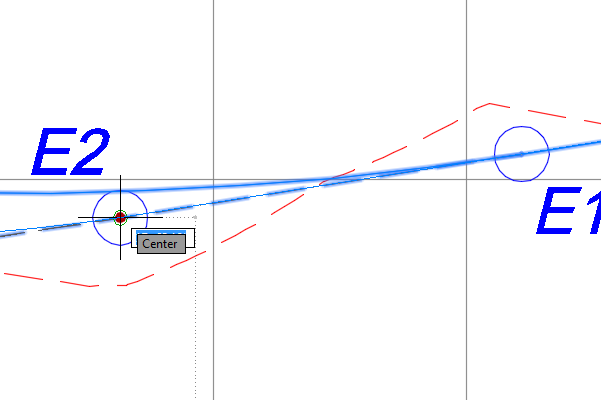
Figure 7-7: Moving the start point or endpoint grip
Exercise 7.5: Edit a Profile Using the Profile Layout Tools
Grips are wonderful tools for editing geometry that is already there, but what if you need to add a PVI or draw a curve? For that, you need the Profile Layout Tools toolbar (see Figure 7-8). This toolbar is the same one you would use to create a profile initially.
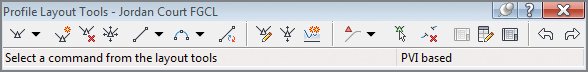
Figure 7-8: Profile Layout Tools toolbar
In this exercise, you’ll use the Profile Layout Tools to edit the Jordan Court profile to better match existing ground and to simplify the design.
- Open the drawing named
Editing Tools.dwglocated in yourChapter 07class data folder. - Click the Jordan Court FGCL profile, and then click Geometry Editor on the ribbon.

This opens the Profile Layout Tools toolbar.
- On the Profile Layout Tools toolbar, click Insert PVI. While holding down the Shift key, right-click and select Endpoint.

- Zoom in to the left end of the profile, and click the sharp break in the existing ground profile that is located at the center of the circle marked A.
- On the Profile Layout Tools toolbar, click Delete PVI. Then click in the circle marked B. Doing so deletes the PVI at this location and removes the slight bend in the profile.

- On the Profile Layout Tools toolbar, click Insert PVIs – Tabular.

- In the Insert PVIs dialog box, enter 19+10 (0+582) for Station and 174.00 (53.000) for Elevation.
- Press the Enter key to create a new line. Then enter 21+55 (0+655) for Station and 173.5 (52.750) for Elevation. Click OK.
- On the Profile Layout Tools toolbar, click the black triangle to the right of the curves button to view the curves menu. Select More Free Vertical Curves ⇒ Free Vertical Parabola (PVI Based), as shown in Figure 7-9.


Figure 7-9: Clicking the Free Vertical Parabola (PVI Based) command
- Click in the circle marked C. Type
150(45), and press Enter to provide the curve length. - Click in the circle marked D. At the command line, type
200(60) for the curve length, and press Enter. - Press Enter to end the command.
- Save and close the drawing.
You can view the results of successfully completing this exercise by opening Editing Tools - Complete.dwg.
Exercise 7.6: Edit a Profile Using Profile Grid View
At times, you may want to adjust your design by telling Civil 3D the exact dimension of a portion of the profile. You can do this in one of two different ways. The first is using Profile Grid View, which opens a tab in Panorama. This tab shows the geometry of the profile in table form and enables you to edit some of the values to adjust the design. The second way, using component-level editing, will be covered in the next exercise.
In this exercise, you’ll use Profile Grid View to make some edits to the PVI stations and elevations of the Jordan Court design profile.
If you haven’t already done so, go to the book’s web page at www.sybex.com/go/civil3d2015essentials and download the files for Chapter 7. Unzip the files to the correct location on your hard drive according to the instructions in the introduction. Then, follow these steps:
- Open the drawing named
Profile Grid View.dwglocated in theChapter 07class data folder. - Click the Jordan Court FGCL profile, and then click Geometry Editor on the ribbon.

- Click Profile Grid View to open the Profile Entities tab and display the numerical version of the profile geometry.

- Change the Station value for Item 3 to 2+70.00 (0+080.00) and the PVI Elevation value to 188.00 (57.00).
Change the remaining items as follows:
ItemStationPVI Elevation48+55.00 (0+260)196.50 (60.0)510+50.00 (0+320)188.50 (57.5)616+90.00 (0+515)164.00 (50.0)
- Close Panorama.
The drawing may not look very different than before because the changes you made were very subtle.
- Save and close the drawing.
You can view the results of successfully completing this exercise by opening
Profile Grid View - Complete.dwg.
Exercise 7.7: Edit a Profile Using Component-Level Editing
The second method for editing the profile design numerically is referred to as component-level editing. With this approach, you open the numerical data for a piece of the profile (such as a line or vertical curve) in a separate window. You do this by clicking the Sub-Entity Editor button on the Profile Layout Tools toolbar and then using the Pick Sub-Entity tool to choose the part of the profile you want to edit.
In this exercise, you’ll use component-level editing to make some more changes to the Jordan Court design profile.
If you haven’t already done so, go to the book’s web page at www.sybex.com/go/civil3d2015essentials and download the files for Chapter 7. Unzip the files to the correct location on your hard drive according to the instructions in the introduction. Then, follow these steps:
- Open the drawing named
Profile Component Level Editing.dwglocated in theChapter 07class data folder. - Click the Jordan Court profile, and then click Geometry Editor on the ribbon.

- Click Profile Layout Parameters on the Profile Layout Tools toolbar to display the Profile Layout Parameters dialog box. (This dialog box is blank when it first appears.)

- Click Select PVI, and then click near the curve at the lowest point on the Jordan Court FGCL profile.

- Change Profile Curve Length to 275 (80). Close the Profile Layout Parameters dialog box and the Profile Layout Tools toolbar.
Again, the drawing doesn’t appear to change much because the edit you made was so subtle.
- Save and close the drawing.
You can view the results of successfully completing this exercise by opening Profile Component Level Editing - Complete.dwg.
Using Design Check Sets and Criteria Files
You first learned about design criteria files and check sets in Chapter 5. These two features enable you to check your design on-the-fly to catch any errors or design flaws as you work. Of course, what’s considered right can differ from place to place and from design type to design type, so these checking tools are customizable. The task of setting them up is usually left to a CAD manager or one of the top CAD users in your company or organization. This is true of most Civil 3D customizations.
As discussed in Chapter 5, the actual details of how design criteria files and check sets are configured can be driven by government entities, such as a department of transportation or planning commission, or according to your own personal design standards or those adopted by your company. Whatever the case, you should be careful not to rely on them 100 percent. Even while using design criteria files and check sets, a solid understanding of design principles is a must. These tools are just a way of making sure you’re applying what you already know, not a substitute for knowing it in the first place.
Exercise 7.8: Apply a Design Check Set
As you learned earlier, a design check set is a collection of one or more design checks. For profiles, there are two types of design checks: line and curve. When a design check set is applied to a profile, Civil 3D flags any violations with a triangular yellow shield marked with an exclamation point. You can hover over the shield to get more information about the violation.
In this exercise, you’ll apply a design check set to the Jordan Court profile and then make some edits to address design violations.
- Open the drawing named
Design Check Set.dwglocated in theChapter 07class data folder. - Click the Jordan Court FGCL profile, and then click Profile Properties on the ribbon.

- In the Profile Properties dialog box, click the Design Criteria tab and check the box next to Use Criteria-Based Design.
- Check the Use Design Check Set box, and select Subdivision.
- Click OK to close the Profile Properties dialog box. Press Esc to clear the grips on the profile and note the two yellow shields near the right end of the profile, as shown in Figure 7-10.
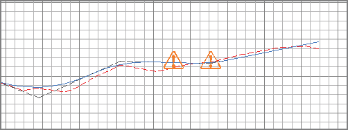
Figure 7-10: Warning symbols indicating design check set violations
- Zoom in to the area where the warning symbols are displayed. Hover the cursor over the symbol on the left.
The tooltip reports that the grade check is being violated for this tangent.
- Click the profile to display its grips. Then click the PVI grip to the left of the warning symbol and move it upward.
- Move the PVI down little by little until both tangent warning symbols disappear indicating that you have satisfied the design check for both tangents.
- Press Esc to clear the selection, and then hover your cursor over the remaining warning symbol.
- Click the profile to display the grips, and then click one of the circular grips at either end of the curve and move it outward to lengthen the curve. When you lengthen the curve enough, the warning symbol disappears.
- Save and close the drawing.
You can view the results of successfully completing this exercise by opening Design Check Set - Complete.dwg.
Exercise 7.9: Apply a Design Criteria File
As you did with alignments, you can assign design criteria files to a profile. The general behavior of design criteria files is the same as it is for design checks: they display warning symbols when certain design parameters aren’t met. However, behind the scenes, design criteria files are much more sophisticated than design check sets, and you can use them to check more types of geometric criteria.
In this exercise, you’ll apply a design criteria file to the Jordan Court profile and then make some edits to address design violations.
- Open the drawing named
Design Criteria File.dwglocated in theChapter 07class data folder. - Click the Jordan Court FGCL profile, and select Profile Properties on the ribbon.

- Click the Design Criteria tab. Check the boxes next to Use Criteria-Based Design and Use Design Criteria File.
- Click the button to the right of the file path, and select the file named
Autodesk Civil 3D Imperial (2011) Roadway Design Standards.xml(Autodesk Civil 3D Metric (2011) Roadway Design Standards.xml). Click Open. - Verify that the box next to Use Design Check Set is unchecked.
- Click OK, and press Esc to clear the selection.
- Hover your cursor over the warning symbol farthest to the left.
The tooltip reports that the minimum passing sight distance isn’t being met (see Figure 7-11).

Figure 7-11: Warning symbol with a tooltip reporting that the passing-sight-distance criterion isn’t being met
- Hover your cursor over the warning symbol at the lowest point of the profile.
- Click the Jordan Court FGCL profile, and then click Geometry Editor on the contextual ribbon tab.

- On the Profile Layout Tools toolbar, click Profile Grid View.

- In Panorama, scroll to the right until you can view the Minimum K For Headlight Sight Distance column.
Note that a warning symbol appears in the row for Item 6 and that the required K value is 26.000 (9.000), as shown in Figure 7-12.
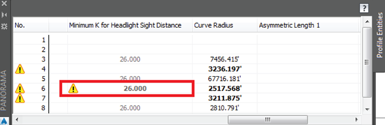
Figure 7-12: A warning symbol in Panorama indicating a violation of the headlight-sight-distance criterion
- Scroll to the left until you can see the K Value column. Change the K value for Item 6 to 26 (9).
- Change the Profile Curve Length for Item 6 to 225 (75). This generates a K value of 27.193 (9.010), so the warning symbol is still suppressed.
- Save and close the drawing.
You can view the results of successfully completing this exercise by opening Design Criteria File - Complete.dwg.