Chapter 12 Designing and Analyzing Boundaries Using Parcels
In the previous chapter, you completed the road-design portion of the example project by creating and displaying cross sections. With the roads in place, it’s now time to look at another aspect of the design: the layout of real-estate lots. Although the road design and lot layout are very different types of designs, they are still dependent on one another because the roads determine the front boundaries of the lots. In the example project, you won’t return to road design; but in a real project, there are often adjustments to the road layout that can affect the parcels as well as other design aspects.
As the designer in this project, you’ll be asked to design the layout of the single-family lots as well as open space areas, community areas, utility easements, and so on. The developer makes money by selling the lots, so the more lots there are to sell, the more profit that can be had. So why not make a thousand tiny little lots? Well, of course, if a lot is too small to fit a house, it will be nearly useless and won’t sell. In addition, other aspects determine minimum size requirements for lots, such as the market the developer is targeting and/or zoning laws. Your job as the designer will be to create as many lots as possible while meeting these minimum size requirements.
In this chapter, you’ll learn to
Understand parcels
Create parcels from objects
Create parcels by layout
Edit parcels
Understanding Parcels
Quite often, a land-development project involves the purchase, consolidation, or subdivision of a piece of real estate. Even if this isn’t the case, the boundary of the developed property must be accurately depicted in the design drawings. It must also be marked in the field to ensure that neighboring properties aren’t encroached on. Yet another potential aspect of a land-development project is accurately determining the location of rights-of-way and easements, whether existing or proposed. Through parcel objects and their associated commands and annotations, the AutoCAD® Civil 3D® software environment provides you with tools for creating, analyzing, and displaying legal boundaries efficiently and accurately.
Understanding Parcel Objects
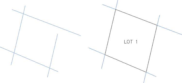
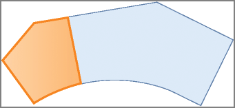
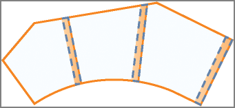
As you have seen with other Civil 3D features, Civil 3D makes use of specialized objects to perform specific tasks. Creating parcels is no different. It involves the use of specialized objects whose behavior makes the process of creating and modifying parcels as efficient as possible. The objects that are applied in this case are called parcel segments. You can think of parcel segments as lines and curves that have been identified as sides of a parcel. They can be drawn from scratch using a special toolbar, or they can be created by converting lines, arcs, and polylines. Parcel segments must be assigned to a site so Civil 3D understands that they should react to one another. When parcel segments in the same site form a closed shape, that shape becomes a parcel object. This is a unique arrangement because you can’t directly create a parcel object; instead, you create other objects to form a closed area, and then Civil 3D creates the parcel object for you (see Figure 12-1).
Figure 12-1: The four parcel segments on the left don’t form a closed shape; therefore, no parcel is created. On the right, a parcel object is created automatically, as shown by the black outline and the LOT 1 label.
In the same manner, any modifications to the fundamental objects that make up a parcel will result in an automatic update to the parcel itself. This is most evident when parcels are labeled with area, bearing, and distance information.
Understanding Sites
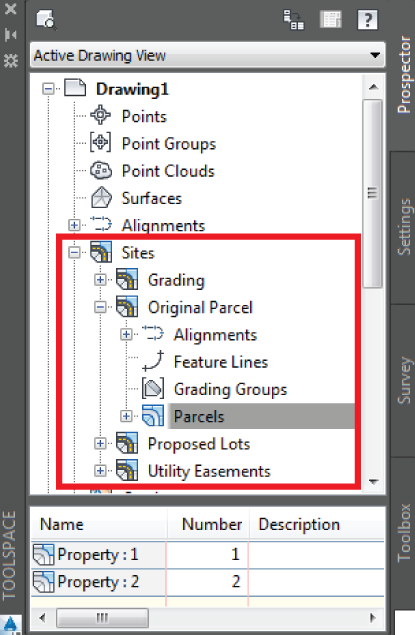
Placing objects within the same site is how you tell Civil 3D that you want these objects to “see” each other and interact. You can also prevent objects from interacting by placing them in different sites. The sites are listed in Prospector, and you can create as many as you need in a given drawing (see Figure 12-2).
Figure 12-2: Sites listed in Prospector, with the contents of one site expanded
When parcel segments are placed in the same site in such a way that they create one or more closed shapes, the closed shapes automatically become parcels. Alignments, feature lines, grading groups, and survey figures can also occupy sites. These objects are able to interact with parcels and with one another. For example, if an alignment crosses through a parcel, the alignment automatically subdivides the parcel to create two parcels. For this to take place, the parcel and the alignment must be in the same site. By the same token, you can prevent the alignment from subdividing the parcel by placing the alignment and parcel in separate sites. In the left image of Figure 12-3, the alignment and parcel are in different sites and therefore don’t interact to create two parcels from one. In the right image of Figure 12-3, the alignment has been moved to the same site as the parcel, causing it to be subdivided automatically.
Figure 12-3: The effect of sites on the interaction between an alignment and a parcel
Creating Parcels from Objects
One way you can create parcels is to use lines, arcs, and polylines that already exist in your drawing and convert them into parcel segments. This technique is often used when the parcel geometry is especially complex or must be drawn based on other geometry in the drawing. Civil 3D provides a few tools for drawing parcel segments directly, but many more drawing and editing commands are available in the AutoCAD® part of Civil 3D. For this reason, you may find it easier to create the necessary geometry using the AutoCAD drafting commands rather than the Civil 3D commands.
Converting basic AutoCAD entities to parcel segments is relatively simple. You launch the command from the ribbon; select the lines, arcs, and/or circles that you would like to convert; and then provide some information about the parcel segments you’re about to create. If the selected objects intersect to create closed shapes, Civil 3D takes care of the rest. You’ll know the parcels have been created when the labels appear in the drawing area and the parcels are listed in Prospector.
Exercise 12.1: Create Parcels from Objects
In this exercise, you’ll create parcels from geometry provided for you. The parcels you create will be the overall project parcel first, then the right-of-way parcel, and finally large areas that will be subdivided into individual lots at a later time.
Open the drawing named Creating Parcels from Objects.dwg located in the Chapter 12 class data folder.
On the Home tab of the ribbon, click Parcel ⇒ Create Parcel From Objects.
Click the green polyline representing the overall parcel boundary. Click the magenta polyline representing the southern right-of-way of Emerson Road. Press Enter.
In the Create Parcels From Objects dialog box, click OK to accept the default settings.
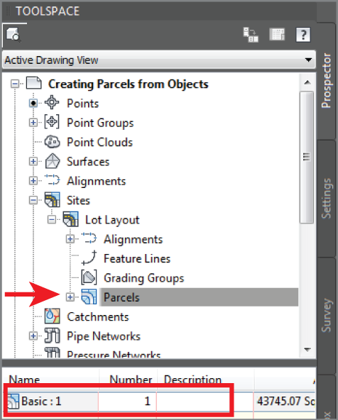
Open Prospector, and expand Sites ⇒ Lot Layout. Right-click Parcels, and select Refresh.
A plus sign appears next to Parcels, and a parcel named Basic : 1 should be listed in the item view area of Prospector (see Figure 12-4).
Figure 12-4: The newly created parcel shown in Prospector
If the item preview icon at the top left of Prospector isn’t depressed, click it.
Right-click Parcels, and verify that there is a check next to Show Preview. If there isn’t, click Show Preview.
Expand Parcels, and then click Basic : 1 listed beneath it.
A preview of the shape of the parcel is shown in the item view area.
Click one of the red polylines in the drawing, right-click, and choose Select Similar.
On the Home tab of the ribbon, click Parcel ⇒ Create Parcel From Objects.
In the Create Parcels – From Objects dialog box, change Parcel Style to Property and click OK.
In Prospector, right-click Parcels and select Refresh. Preview the parcels in the item view window as you did earlier with the Basic : 1 parcel.
Click one of the dashed right-of-way lines, right-click, and then pick Select Similar.
Again, on the Home tab of the ribbon, click Parcel ⇒ Create Parcel From Objects. Click OK to dismiss the Create Parcel – From Objects dialog box with the default settings.
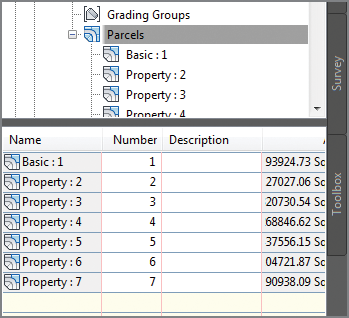
Refresh, and preview the parcels in Prospector again. Now there are seven parcels in all (see Figure 12-5).
Figure 12-5: Seven parcels are now listed in the Prospector item view.
Save and close the drawing.
You can view the results of successfully completing this exercise by opening Creating Parcels from Objects - Complete.dwg.
Creating Parcels by Layout
Earlier in this chapter, you read about the advantage of using basic AutoCAD drafting commands to produce parcel geometry. As mentioned, these commands are great for drawing lines and curves based on general geometric principles. But what if you need to create parcels that occupy a certain area, parcel segments that are perpendicular to a road frontage, or parcels that meet a minimum depth requirement based on zoning laws? These are all criteria that are specific to property boundaries, and they are all built into the Civil 3D Parcel Layout Tools toolbar. When you launch the Parcel Layout Tools from the ribbon, they appear on a specialized toolbar similar to what you have seen for alignments and profiles.
Using the Lot Line Tools
The first few buttons on the Parcel Layout Tools toolbar are used for basic parcel-segment drafting that is similar to using basic AutoCAD line and curve commands, as shown in Table 12-1. You can use these tools to draw parcels freehand or to retrace geometry that already exists in the drawing.
Exercise 12.2: Create Parcels Using the Lot Line Tools
In this exercise, you’ll draw new parcel geometry using the Parcel Creation Tools command. You’ll create a common area parcel near the entrance to the development as well as a parcel representing land that is to remain the property of the individual owner.
Open the drawing named Using the Lot Line Tools.dwg located in the Chapter 12 class data folder.
On the Home tab of the ribbon, click Parcel ⇒ Parcel Creation Tools.
On the Parcel Layout Tools toolbar, click Add Fixed Line – Two Points. Click OK to accept the defaults in the Create Parcels – Layout dialog box.
Zoom in to Jordan Court near station 4+00 (0+100). Hold down the Shift key, and right-click to open the Object Snap context menu.
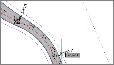
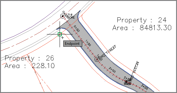
Click Endpoint. Then click the end of the magenta curve at station 4+20.38 (0+128.13), as shown in Figure 12-6.
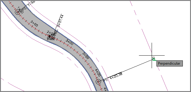
Hold down the Shift key, and right-click. Select Perpendicular.
Click the magenta back-lot line, as shown in Figure 12-7. Press Esc twice to end the command.
You have created a new parcel near the front entrance that will be used for a community clubhouse and administrative offices.
Figure 12-6: Snapping to the end of the curve to begin creating a new parcel line
Figure 12-7: Snapping to a location that is perpendicular to the eastern lot line
Click Parcel ⇒ Parcel Creation Tools on the Home tab of the ribbon.
Click Draw Tangent – Tangent With No Curves, and then click OK to dismiss the Create Parcels – Layout dialog box.
Using the Endpoint object snap, trace the fence line that surrounds the existing farm buildings. Begin at the north end of the fence, and work toward the south and west.
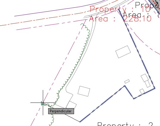
Once you have selected the last point on the fence, use the Perpendicular object snap to select the western boundary line, as shown in Figure 12-8.
Press Esc twice to exit the Parcel command.
Save and close the drawing.
You can view the results of successfully completing this exercise by opening Using the Lot Line Tools - Complete.dwg.
Figure 12-8: Completing the farm property boundary by clicking a point perpendicular to the west property boundary
Using the Parcel Sizing Tools
The next set of tools on the Parcel Layout Tools toolbar that you’ll learn about is by far the most powerful: the Parcel Sizing Tools. These tools enable you to lay out multiple lots within a predetermined area, with each lot meeting the size parameters you specify. These tools will create the bulk of the lots in a residential land-development design such as the example project you’re working on.
You can use the following three tools to create new lots based on size:
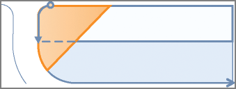
Slide Line – Create This tool creates one or more lots by sliding a line along the frontage until all size and dimension requirements are met.
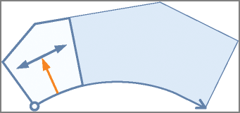
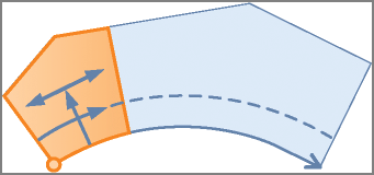
Swing Line – Create This tool creates one or more lots by rotating a line around a fixed swing point and intersecting it with a lot line across from the swing point. The result is one or more lots that radiate outward from the swing point.
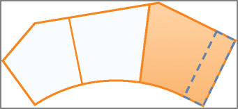
Free Form Create This tool creates a lot by attaching one end of a line to a parcel segment and extending that line along a specified angle (usually perpendicular) until it intersects another parcel segment.
Exercise 12.3: Create Parcels Using the Parcel Sizing Tools
In this exercise, you’ll create several new parcels using the parcel sizing tools on the Parcel Layout Tools toolbar.
Open the drawing named Using the Parcel Sizing Tools.dwg located in the Chapter 12 class data folder.
On the Home tab of the ribbon, click Parcel ⇒ Parcel Creation Tools.
On the Parcel Layout Tools toolbar, expand the button containing the parcel sizing tools, and click Slide Line – Create.
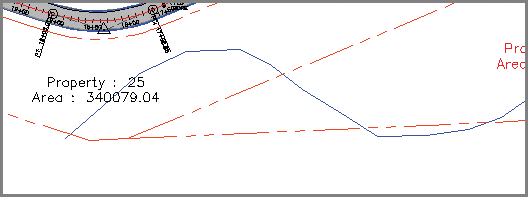
Click OK to dismiss the Create Parcels – Layout dialog box. When you’re prompted to select a parcel, click the label that reads Property : 25 at the southwest end of the project.
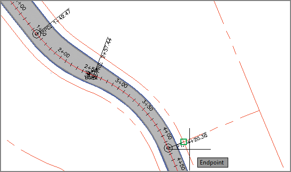
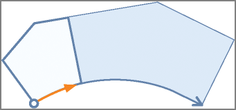
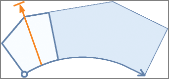
When you’re prompted to select the first point on the frontage, click the western endpoint of the lot line you previously created at station 4+20.38 (0+128.13), as shown in Figure 12-9.
Figure 12-9: Selecting the beginning point of the frontage
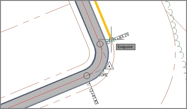
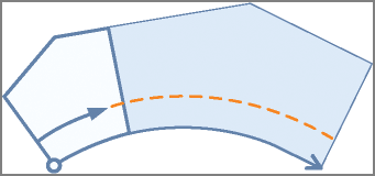
Move your cursor in a southeastern direction along the frontage line. Note the orange “highlighter” that follows your cursor. Snap to the endpoint of the curve at station 11+83.29 (0+360.67), as shown in Figure 12-10.
Figure 12-10: Selecting the endpoint of the frontage
When you’re prompted to specify the angle, type 90 at the command line, and press Enter.
A preview of the new parcel appears near the start point of the frontage.
Press Enter to accept the current sizing parameters and create the parcel. Press Esc to exit the current command but keep the Parcel Layout Tools toolbar open.
Click Swing Line – Create, and click the label that reads Property : 2 near the southeastern corner of the project.
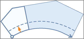
When you’re prompted for the start point of the frontage, snap to the northern endpoint of the Property : 2 parcel, as shown in Figure 12-11.
Figure 12-11: Selecting the beginning point of the frontage
When you’re prompted for the endpoint of the frontage, move your cursor in a westerly direction along the property line and snap to the western endpoint of the same parcel (see Figure 12-12).
Figure 12-12: Selecting the ending point of the frontage
When you’re prompted for the swing point, use an Endpoint object snap to select the property corner just south of the Property : 2 label.
A preview of the parcel is displayed using the current Minimum Area setting of 10890 Sq. Ft. (1500 sq.m.).
If the chevron at the right end of the Parcel Layout Tools toolbar is pointing downward, click it. If not, skip to the next step.
In the expanded area beneath the Parcel Layout Tools toolbar, type 1acre (0.4hectare) for the Minimum Area value, and press Enter. The preview is updated to reflect the new area.
Press Enter to create the parcel.
One scenario where this type of parcel might be used would be if an environmental agency requested a 1-acre (0.4-hectare) preservation area to mitigate environmental impacts elsewhere on the site.
Press Esc to clear the current command. On the Parcel Layout Tools toolbar, click Free Form Create. Move your cursor along the property line to the east of the Property : 25 label.
Note how the line preview attaches itself to the parcel segment and extends outward until it intersects another parcel segment.
With your cursor on the west side of the line, snap to the midpoint of the parcel segment. When you’re prompted for a direction, press Enter to specify perpendicular.
Press Esc twice to clear the current command and close the Parcel Layout Tools toolbar.
Save and close the drawing.
You can view the results of successfully completing this exercise by opening Using the Parcel Sizing Tools - Complete.dwg.
Using Parcel Sizing and Layout Parameters
The Parcel Layout Tools toolbar includes commands for creating new parcel geometry as well as editing it. The toolbar expands downward to reveal parameters that determine the dimensions of the lots that are created. This enables you to include size requirements in your parcel design that may have been requested by the developer or dictated by zoning laws.
The layout parameters available to you are listed here. The image next to each parameter matches the schematic preview shown in the bottom of the Parcel Layout Tools toolbar as you click each parameter:
Minimum Area This is the minimum area occupied by the lot. Minimum area is a common requirement that designers must meet to satisfy zoning requirements.
Minimum Frontage This is the minimum length of the lines or arcs that make up the side of the lot that is coincident with a road right-of-way. This is also a common parameter that designers must meet to satisfy zoning requirements.
Use Minimum Frontage At Offset Some zoning regulations allow the frontage to be measured at the building setback line rather than at the frontage line itself. This would enable you to create a larger number of smaller lots, especially when creating lots along the outside of a curve.
Frontage Offset This parameter is typically used to define the building setback line.
Minimum Width This is the minimum width allowed for the resulting parcel.
Minimum Depth This is the minimum depth allowed for the parcel, measured perpendicular to the frontage at its midpoint.
Use Maximum Depth This parameter prevents the development of exceedingly deep lots, potentially enabling the area to be subdivided more efficiently.
Maximum Depth This is the maximum depth allowed for the parcel, measured perpendicular to the frontage at its midpoint.
Multiple Solution Preference – Use Shortest Frontage When multiple solutions are possible, the one that produces the shortest frontage is selected.
Multiple Solution Preference – Use Smallest Area When multiple solutions are possible, the one that produces the smallest area is selected.
In addition to the parcel-sizing parameters, there are parcel-layout parameters that affect the creation of multiple parcels. The first is Automatic Mode, which determines whether parcels are created individually or all at once, as follows:
Automatic Mode – On Multiple parcels are created within the selected area based on the parameters that have been specified.
Automatic Mode – Off Parcels are created one at a time, and you’re prompted for information for each parcel.
The second parcel-layout parameter is Remainder Distribution, which determines what is done with the “leftover” area after all parcels that meet the size requirements have been created. The Remainder Distribution options are as follows:
Create Parcel From Remainder A new parcel is created that is smaller than the specified sizing parameters.
Place Remainder In Last Parcel The last parcel is oversized by adding the remainder to it.
Redistribute Remainder All parcels are oversized by a small amount so that the leftover area is spread across all parcels.
Exercise 12.4: Create Multiple Parcels
In this exercise, you’ll create multiple parcels by using the Slide Line Create command with Automatic Mode turned on.
Open the drawing named Using Parcel Sizing Parameters.dwg located in the Chapter 12 class data folder.
On the Home tab of the ribbon, click Parcel ⇒ Parcel Creation Tools. On the Parcel Layout Tools toolbar, change Automatic Mode to On.
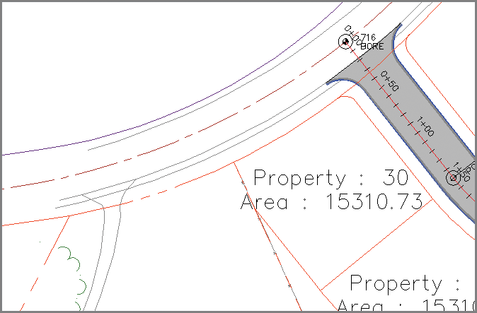
Click Slide Line – Create, and then click OK to dismiss the Create Parcels – Layout dialog box. When you’re prompted to select a parcel, click the label that reads Property : 30.
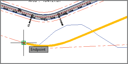
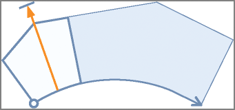
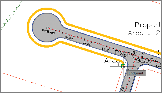
When you’re prompted for the start point of the frontage, snap to the endpoint of the right-of-way line at the entrance of Jordan Court, as shown in Figure 12-13.
Figure 12-13: Selecting the beginning point of the frontage
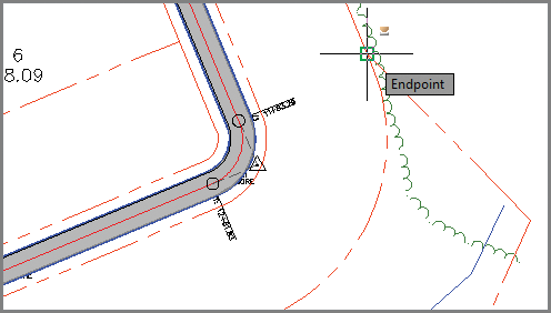
When you’re prompted for the endpoint of the frontage, move your cursor along the west right-of-way line of Jordan Court and then along the north right-of-way line of Madison Lane. Move your cursor around the Madison Lane cul-de-sac, and snap to the endpoint of the right-of-way line at the intersection of Madison Lane and Logan Court, as shown in Figure 12-14.
Figure 12-14: Selecting the ending point of the frontage
When you’re prompted to specify an angle, press Enter.
On the Parcel Layout Tools toolbar, type 0.333acres (or 0.135hectares) for Minimum Area, and press Enter. The preview updates.
Change the following settings (noting how the preview updates after each):
Minimum Frontage: 100 (35)
Frontage Offset: 25 (8)
Remainder Distribution: Redistribute Remainder
Multiple Solution Preference: Use Smallest Area
Press Enter to create the parcels. Press Esc twice to end the command.
Save and close the drawing.
You can view the results of successfully completing this exercise by opening Using Parcel Sizing Parameters - Complete.dwg.
Editing Parcels
As you have seen with other design elements, the ability to edit parcels is even more important than their initial layout. Civil 3D provides you with three fundamental tools to edit your parcel geometry: grips, Edit Geometry commands, and Parcel Layout Tools.
Editing Parcels Using Grips
Graphically editing parcels is fairly simple when compared to editing alignments or profiles. There are only two types of grips to learn: the square grip and the diamond-shaped grip. The square grip is simply the standard grip that allows movement in any direction with no restriction. The diamond-shaped grip is displayed on parcel lines that have been created using the Parcel Layout Tools. These grips slide one parcel line along another parcel line or curve while maintaining the angle (usually perpendicular) between the two lines.
Exercise 12.5: Edit Parcels with Grips
In this exercise, you’ll experiment with grip-editing parcel lines and observing their behavior.
Open the drawing named Editing Parcels Using Grips.dwg located in the Chapter 12 class data folder.
Zoom in to the parcel labeled Property : 28. Click the northern side of this parcel, and notice the square grips that appear on either end of the line.
Click the eastern square grip to select it. Move your cursor around the screen, and notice the behavior of this grip.
Hold down the Shift key, and right-click to reveal the object snap context menu. Select Nearest.
Pick a point somewhere along the property line that forms the eastern side of the lot.
Press Esc to clear your selection. Click the line that forms the southern boundary of this parcel.
Notice that a single diamond-shaped grip appears.
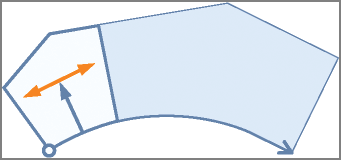
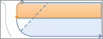
Click the diamond-shaped grip, and slide it along the parcel line it’s attached to. Slide it north to the curved areas, and notice how it stays perpendicular to the parcel segments it’s attached to (see Figure 12-15).
Figure 12-15: As it’s moved with the diamond-shaped grip, the parcel line stays perpendicular to the parcel segments it’s associated with.
Pick a new location for the line, and note the change to the parcel label.
Save and close the drawing.
You can view the results of successfully completing this exercise by opening Editing Parcels Using Grips - Complete.dwg.
Editing Parcels Using the Edit Geometry Commands
When you need to modify the parcel lines and curves themselves, you can use the commands found on the Edit Geometry panel of the Parcel ribbon tab. The commands included on this panel are as follows:
Insert PI Inserts an angle point into a parcel line segment.
Delete PI Removes an angle point from a parcel line segment.
Break Creates a gap in a parcel segment.
Trim Shortens a parcel segment using some other entity as a cutting edge.
Join Joins two parcel segments together.
Reverse Direction Changes the direction of the parcel segment.
Edit Curve Allows you to change the radius of a parcel curve segment.
Fillet Replaces an angle point with a parcel curve segment that is tangent at either end.
Fit Curve Replaces a series of parcel line segments with a parcel curve segment.
Stepped Offset Similar to the AutoCAD offset command, except that it prompts you for an elevation; the resulting entity is a polyline, not a parcel segment.
Exercise 12.6: Edit Parcels with the Edit Geometry Commands
In this exercise, you’ll improve the geometry of several parcels using the Edit Geometry commands on the ribbon.
Open the drawing named Editing Parcels Using Edit Commands.dwg located in the Chapter 12 class data folder.
Zoom in to the area of the farm buildings, and notice the small triangular parcel labeled Property : 26.
Click the Property : 26 label. If the Edit Geometry panel isn’t visible on the ribbon, click Edit Geometry.
Click Trim on the Edit Geometry panel of the contextual ribbon. When you’re prompted for the cutting edge, select the parcel segment that is drawn along the fence. Press Enter.
When you’re prompted for the objects to trim, click the west side of the small triangular parcel. The Property : 26 parcel disappears (see Figure 12-16), and the area of Property : 27 is updated
Figure 12-16: Trimming the parcel segment has removed the small triangular parcel.
Press Esc to clear the current command. Pan southward, and click the Property : 7 parcel label. Click Edit Curve on the ribbon.
Click the curve just north of the Property : 7 label. In the Edit Feature Line Curve dialog box, enter 250 (85) for the radius value and click OK. The parcel is updated.
Press Esc twice to clear the current command and the current selection. Zoom in to the western end of the Property : 2 parcel.
Click the north boundary of the NoProperty : 2 parcel, and then click Delete PI on the ribbon. Click the triangle marker at the western end of the parcel line to delete the PI at that location.
Press Esc twice to end the previous command, and then click the parcel line again to reveal its grips. Click the westernmost grip, and snap it to the center of the red circle.
The parcel geometry has been improved (see Figure 12-17).
Figure 12-17: The western end of the parcel has been simplified.
Save and close the drawing.
You can view the results of successfully completing this exercise by opening Editing Parcels Using Edit Commands - Complete.dwg.
Editing Parcels Using the Parcel Layout Tools
For the most advanced parcel editing, you can look to the Parcel Layout Tools toolbar. This toolbar includes some of the same tools the Edit Geometry panel of the Parcel ribbon tab includes, such as Insert PI and Delete PI. You’ll also find editing versions of the parcel-sizing commands that you used earlier to create parcels. The Slide Line – Edit and Swing Line – Edit commands work much like their Create counterparts, but instead of creating new parcel lines, they slide or rotate existing parcel lines to meet new size requirements. In addition, you can create a parcel union that combines multiple parcels into a single identity. There is also a command that will dissolve this union, returning the component parcels to their individual status.
Exercise 12.7: Edit Parcels with the Parcel Layout Tools
In this exercise, you’ll use a few of the Parcel Layout Tools to edit parcels.
Open the drawing named Editing Parcels Using the Layout Tools.dwg located in the Chapter 12 class data folder.
Click the Property : 28 parcel label, and then click Parcel Layout Tools on the ribbon.
On the Parcel Layout Tools toolbar, type 0.5acres (or 0.20hectares) for the minimum area, and press Enter.
Expand the Parcel Sizing Tools, and click Slide Line – Edit. Click OK to dismiss the Create Parcels – Layout dialog box.
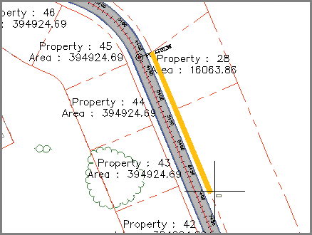
When you’re prompted to select a lot line, click the southern boundary line of Property : 28.
When you’re prompted to select a parcel to adjust, click somewhere in the Property : 28 parcel.
When you’re prompted for the start point of the frontage, snap to the northwest corner of the Property : 28 parcel.
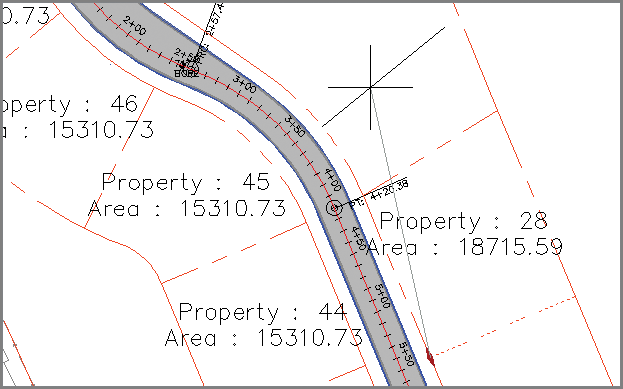
Move your cursor southward along the right-of-way line, and click somewhere near station 7+00 (0+210), as shown in Figure 12-18.
When you’re prompted to specify the angle, press Enter. A preview of the resized parcel is shown.
Press Enter to complete the command and resize the parcel.
Figure 12-18: Defining the frontage for the parcel-editing command
Press Esc three times to clear the current command and clear the current selection. Click the Property : 27 label, and then click Parcel Layout Tools on the ribbon.
On the Parcel Layout Tools toolbar, click Parcel Union.
When you’re prompted for the destination parcel, click the Property : 3 label. The Property : 27 label disappears, and the area of Property : 3 is updated.
Expand the Parcel Union icon, and select Dissolve Parcel Union.
Click the Property : 3 label. Two new parcels are created to replace the original parcels 3 and 27.
Save and close the drawing.
You can view the results of successfully completing this exercise by opening Editing Parcels Using the Layout Tools - Complete.dwg.