Chapter 17
Designing New Terrain
With the completion of the pipe networks, the design of the road is nearly finished. It’s now time to move on to the next area of the design: the shaping of the land, or grading, of the adjacent areas. In Chapter 9, “Designing in 3D Using Corridors,” you designed a 3D model of the road in the form of a corridor. This model will serve as a basis for much of the adjacent design that will take place, such as the shaping of individual lots and grading in the stormwater management area.
Each of these areas has unique design objectives. The individual lots will be shaped so that homes can be built on them without requiring significant earthmoving. The stormwater management area will require a pond to serve as a means of collecting and treating the stormwater runoff. These designs will serve as opportunities for you to study the two primary grading tools contained in the AutoCAD® Civil 3D® software: feature lines and grading objects.
In this chapter, you’ll learn to
- Understand grading
- Understand feature lines
- Create feature lines
- Edit feature lines
- Understand grading objects
- Create grading objects
- Edit grading objects
Understanding Grading
Grading is the term that is most often used to describe the shaping of the land as a construction or design activity. From a design perspective, it’s usually considered different than corridor design, which is also a form of terrain shaping but most often used for long, uniform, linear designs such as roads, channels, and so on. The term grading is typically used to describe shaping the land in small areas or modeling features that aren’t long and uniform.
The final product of a grading design is a surface—the same type of object you used to model the existing terrain in Chapter 4, “Modeling the Existing Terrain Using Surfaces.” As you may recall, to create a surface representing existing ground (EG) elevations, you use breaklines drawn along linear terrain features such as curb lines, ditch lines, and so on. You can use the Civil 3D tools to make these breaklines from data collected in the field by surveyors. To create a design surface, you draw breaklines along curbs and ditch lines that are going to be built in the field. The process is fundamentally the same as creating an EG surface except that, in this case, the linear features are part of your design. For example, in Figure 17-1, you see the grading design for a pond represented by the red and blue contours. Civil 3D tools were used to draw the edges of this pond according to the required design specifications such as size, shape, depth, and so on. The objects representing the edges were then used to build a pond surface.
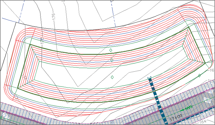
Figure 17-1: A grading design for a pond
Understanding Feature Lines
In Chapter 4, you used survey figures to serve as breaklines in the EG surface. For a design surface, you’ll use feature lines for most of your breaklines. Survey figures and feature lines are fundamentally similar: They are three-dimensional linear objects that can be named, stylized, and shown in Prospector. The primary difference is that you design feature lines, whereas survey figures are driven by data collected in the field.
Understanding Sites
When working with feature lines, you have to consider the use of sites. Feature lines in the same site are “aware” of one another and will try to interact if the opportunity presents itself. For example, if one feature line crosses over another feature line in the same site, one of the feature lines will bend so the two share the same elevation at the intersection point. The point where they intersect is called a split point. In cases where this interaction needs to be prevented, you can simply place each feature line in its own site. Figure 17-2 shows two crossing feature lines in plan view (left) and 3D view (right). Because these two feature lines are in the same site, a split point is created, causing the red feature line to bend so that it can match the green feature line.
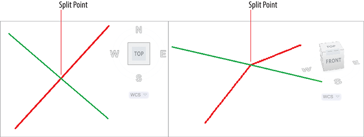
Figure 17-2: Two crossing feature lines that occupy the same site
Understanding Feature-Line Geometry
Feature lines have two types of points that define their geometry: PIs and elevation points. A PI is represented by a square grip and can be modified in all three dimensions. An elevation point is represented by a circle grip and has more constrained editing behavior. Figure 17-3 shows both types of grips on the same feature line. The elevation of an elevation point can be edited, but its location in plan view must slide along the feature-line geometry determined by the PIs. This constrained behavior is actually quite handy because you can create many elevation points on a simple plan view shape such as a rectangle.
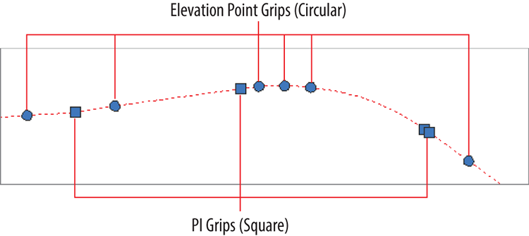
Figure 17-3: A plan view of PI and elevation-point grips on a feature line
Creating Feature Lines

Civil 3D provides a comprehensive set of tools for creating feature lines. They can be drawn from scratch, by converting an AutoCAD® polyline, or by extracting them from more complex Civil 3D objects such as corridors or profiles. When drawing a feature line from scratch, you must provide the elevation of each PI. For all other methods, the elevations are obtained from the object you have selected.
Exercise 17.1: Create Feature Lines
In this exercise, you’ll create feature lines representing elevations along a lot boundary as well as elevations for a building pad within the interior of the lot. You’ll create one feature line from a corridor, another from scratch by drawing it, and a third by selecting objects in the drawing.
- Open the drawing named
Creating Feature Lines.dwglocated in theChapter 17class data folder.This drawing is zoomed in to lot 25 in the top-right and bottom-right viewports. Also notice that the corridor layer has been thawed to reveal the road corridor.
- On the Home tab of the ribbon, click Feature Line ⇒ Create Feature Line From Corridor.

- When prompted on the command line to select a corridor feature line, in either the top-right or bottom-right viewport, click the edge of the corridor that aligns with the front of lot 25.
The Create Feature Line From Corridor dialog box opens.
- Verify that Site is set to Lot Grading. For Style, select Lot Grading – ROW, and then click OK.
The new feature line is displayed as a thick red line.
- Press Esc to end the previous command. On the Home tab of the ribbon, click Feature Line ⇒ Create Feature Line.

- On the Create Feature Lines dialog, for Style, select Lot Grading, and then click OK. When prompted to specify the start point, in the top-right viewport, use the Center object snap to select the center of the red circle at the north corner of lot 25.
- When you’re prompted to specify an elevation, press Enter. When prompted to specify the next point, in the top-right viewport, use the Endpoint object snap to pick the west corner of lot 25.
- When prompted to specify an elevation on the command line, click
Surfaceto invoke the Surface option. - Verify that EG is selected, and click OK.
- Press Enter to accept the elevation.
- When prompted to specify the next point, on the command line, click
Arcto invoke the Arc option. When prompted to specify the arc endpoint on the command line, clickSecondpntto invoke the Secondpnt option. - When prompted to specify the second point, in the top-right viewport, use the Nearest object snap to select a point along the back line of lot 25.
- When prompted to specify the endpoint of the arc, in the top-right viewport, use the Endpoint object snap to select the south corner of lot 25.
- When prompted to specify the elevation, at the command line, click
SUrfaceand press Enter to accept the default elevation of 190.456 (58.027). - When prompted to specify an arc endpoint, at the command line, click
Line. When prompted to specify the next point, in the top-right viewport, use the Center object snap to pick the circle at the east corner of lot 25. - When prompted to specify the elevation, press Enter. Press Esc to end the command.
- On the Home tab of the ribbon, click Feature Line ⇒ Create Feature Lines From Objects. When prompted to select an object, click the rectangle at the center of lot 25, and press Enter.

- On the Create Feature Lines dialog, check the box next to Style, and select Lot Grading. Click OK.
- Save and close the drawing.
You can view the results of successfully completing this exercise by opening Creating Feature Lines - Complete.dwg.
Editing Feature Lines
Civil 3D provides an extensive set of tools for editing feature lines. The tools are divided into two categories represented by two panels on the Feature Line ribbon tab: Edit Geometry and Edit Elevations (see Figure 17-4).
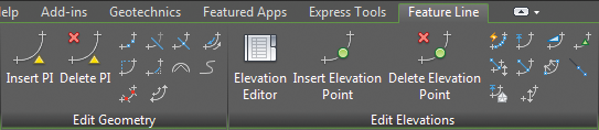
Figure 17-4: The Edit Geometry and Edit Elevations panels of the Feature Line ribbon tab
Using Edit Geometry Commands
The feature-line geometry editing commands provided by Civil 3D are as follows:
- Insert PI Use this command to insert a new PI at a point you specify. A PI can be edited in all three dimensions.

- Delete PI Use this command to remove PIs from the feature line.

- Break Use this command to break one feature line into two feature lines. You can do this by creating a gap between the two feature lines, or you can have them meet end to end.

- Trim Use this command to shorten a feature line by making it end precisely at another object.

- Join Use this command to join two or more feature lines to make one feature line. If there is a gap between the two feature lines, it must lie within a certain tolerance or they won’t be joined.

- Reverse Use this command to change the direction of the feature line. This swaps the beginning and ending points as well as reverses the direction of stationing. This can affect editing and labeling.

- Edit Curve Use this command to change the radius of a feature-line curve.

- Fillet Use this command to add a feature-line curve where there is currently a PI. The command includes options to set the radius of the curve and to create multiple fillets at once.

- Fit Curve Use this command to replace a series of line segments with an arc. This helps to simplify the feature line by replacing multiple points with an arc. This command differs from the Smooth command in that you can control where curves are created. Also, the curves it creates are static, meaning they don’t change when adjacent geometry changes.

- Smooth Use this command to replace PIs with curves. This command is different from the Fit Curve command in that it creates curves for the entire feature line and the curves are dynamic, meaning they remain tangent as the feature line is modified.

- Weed Use this command to simplify a feature line by reducing the number of vertices. The command includes several options for determining which vertices to remove.

- Stepped Offset This command creates a new feature line that is parallel to another. The command includes several options for determining the elevations of the new feature line.

Exercise 17.2: Edit Feature Lines with Geometry Commands
In this exercise, you’ll edit the feature line you created in the previous exercise and then join it to another feature line.
- Open the drawing named
Editing Feature Line Geometry.dwglocated in theChapter 17class data folder. - Click the green feature line. If the Edit Geometry panel isn’t visible, click Edit Geometry on the ribbon.

- Click Insert PI. When you’re prompted to specify a point, use the Center object snap to select the center of the blue circle.

- When prompted to specify an elevation, on the command line, click
Surfaceto invoke the Surface option.The Select Surface dialog box opens.
- Verify that EG is selected, and click OK. Press Enter to accept the elevation shown on the command line.
- When prompted to specify the next point, use the Center object snap to select the center of the red circle.
- When prompted to specify an elevation on the command line, click
Surfaceto invoke the Surface option. Press Enter again to accept the surface elevation. - Press Esc twice to clear the previous command. Click the green feature line, and then click Fit Curve on the ribbon.

- When prompted to specify a point on the command line, click
Pointsto invoke the Points option. - When prompted to specify a start point, use the Center object snap to select the center of the blue circle.
- Use the Center object snap to select the center of the red circle. Press Esc twice to end the command and clear the selection.
- Click any feature line in the drawing, and then click Break on the ribbon.

- When prompted to select an object to break, click the blue perimeter feature line for lot 25.
- When prompted to specify a second break point, on the command line, click
First pointto invoke the First point option. - Use the Endpoint object snap to select the back corner where lots 25 and 26 meet.
- When prompted to select the second break point, repeat the previous step to select the same point again. Press Esc twice to end the command and clear the selection.
- Click the blue feature line at the back of lot 25, and then click Join on the ribbon.

- Click the green feature line, and then press Esc twice to end the command and clear the selection.
The green changes to blue, indicating that the feature lines are joined to create a single feature line (see Figure 17-5).
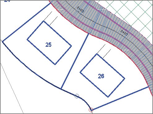
Figure 17-5: The result of editing the feature lines in this exercise
- Save and close the drawing.
You can view the results of successfully completing this exercise by opening Editing Feature Line Geometry - Complete.dwg.
Using Edit Elevation Commands
The feature-line elevation-editing commands provided by Civil 3D are as follows:
- Elevation Editor Use this command to open the Grading Elevation Editor tab in Panorama. From here, you can perform a number of edits while viewing all the feature-line data at once.

- Insert Elevation Point Use this command to create one or more elevation points on a feature line.

- Delete Elevation Point Use this command to simplify a feature line by removing elevation points from it.

- Quick Elevation Edit Use this command to interactively edit the elevations and slopes of a feature line. The command uses tooltips to show you elevations, slopes, and slope directions.

- Edit Elevations Use this command to edit individual points and segments on the command line.

- Set Grade/Slope Between Points Use this command to set a constant grade through multiple points. You do this by specifying a start point and an endpoint, and the command calculates the elevations of any points in between.

- Insert High/Low Elevation Point Use this command to have Civil 3D calculate a high or low point on a feature line. You do this by selecting two points and specifying the slope that should be projected from each point. Civil 3D then calculates the intersection of the two slopes and creates a point at the correct location and elevation. This command is especially useful for setting high and low points along curb lines to control drainage.

- Raise/Lower By Reference Use this command to adjust all the elevations of a feature line simultaneously by specifying a reference point and an elevation difference.

- Set Elevation By Reference Use this command to calculate the elevations of individual points on a feature line by specifying a reference point and an elevation difference for each point.

- Adjacent Elevations By Reference Use this command to project the elevations from one feature line to another while providing an elevation difference, if desired. This command is especially useful for parallel feature lines such as curb lines or wall lines.

- Grade Extension By Reference Use this command to calculate the elevation of a point on a feature line by extending the grade of another feature line.

- Elevations From Surface Use this command to project a feature line onto a surface. This command has the option to create elevation points at locations where the feature line crosses triangle edges in the surface. When this option is used, the feature line becomes an exact match to the terrain represented by the surface.

- Raise/Lower Use this command to edit all the elevations of a feature line simultaneously by providing an elevation difference.

Exercise 17.3: Edit Feature Lines with Elevation Commands
In this exercise, you’ll use the feature-line elevation-editing commands to place the lot 25 building pad at the correct elevation and to make the back-lot lines for lots 25 and 26 match existing ground elevations more closely.
- Open the drawing named
Editing Feature Line Elevations.dwglocated in theChapter 17class data folder. - Click any feature line in the drawing. If the Edit Elevations panel isn’t visible, click Edit Elevations on the ribbon.

- Click Quick Elevation Edit. Place your cursor over the north corner of lot 25.

- Place your cursor at each corner of lot 25, and take note of the elevations.
- Press Esc twice to end the current command and clear the feature-line selection. Click the building pad feature line of lot 25.
- On the ribbon, click Raise/Lower By Reference.

- When prompted to specify a reference point, invoke the Endpoint object snap, and place your cursor on the south corner of lot 25, but don’t click the mouse.
- Look at the coordinate readout at the bottom center of your screen. If the third value in the coordinate readout is 0.0000, press the Tab key. Keep pressing the Tab key until the value reads 190.4564 (58.027), as shown in Figure 17-6.
The Tab key allows you to toggle between the parcel geometry, which is at elevation zero, and the feature lines, which are at true design elevations.
- With the proper value shown in the coordinate readout, click the point to snap to it.
- When prompted to specify a point on the huilding pad feature line, click the south corner of the building pad feature line. When you’re prompted to specify the grade, type 2 and press Enter.
If you watch the lower-right viewport carefully, you’ll see the feature line move upward to join the perimeter feature line.
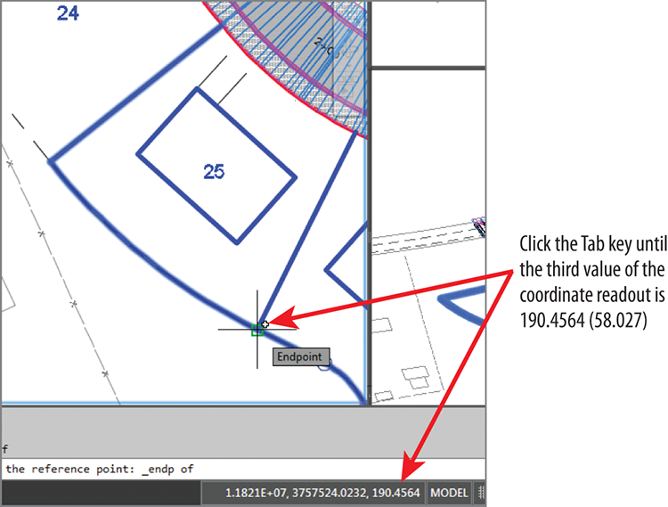
Figure 17-6: Using the Tab key and coordinate readout to select the correct elevation

- Press Esc to clear the previous selection. Click the feature line that represents the rear of the lots, and then click Elevations From Surface on the ribbon.
- On the Set Elevations From Surface dialog, verify that EG is selected and that the box next to Insert Intermediate Grade Break Points is checked. Click OK.
- At the command line, click
Partialto invoke the Partial option. Select the feature line representing the rear of the lots. - When prompted to specify the start point, click the west corner of lot 25, and then click the south corner of lot 26 to specify the endpoint.
- Press Enter to complete the command.
A number of circular grips are now visible on the feature line (see Figure 17-7). These represent additional elevation points that were required for the feature line to match the surface precisely.
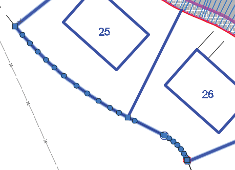
Figure 17-7: Circular grips mark elevation points added to match the feature line to the surface.
- Save and close the drawing.
You can view the results of successfully completing this exercise by opening Editing Feature Line Elevations - Complete.dwg.
Understanding Grading Objects
At times, you’ll want Civil 3D to calculate the location, shape, and elevations of feature lines rather than designing them yourself. Examples of this situation would be projecting a slope through a certain distance or elevation or finding the intersection of a slope with a surface. For these cases, Civil 3D provides the grading object. Figure 17-8 shows a pond design composed of several grading objects, each one using a different set of parameters to calculate an edge that defines the shape of the pond.
A grading object is a collection of feature lines whose geometry, location, and elevation are calculated by Civil 3D based on design parameters that you have applied to a feature line. That’s quite a daunting definition, so here’s a look at it broken down into several parts:
- A grading object is a collection of feature lines (and other things not important to name at this time), so it behaves as one object. The feature lines in this collection have many of the same characteristics as individual feature lines as well as some unique characteristics that relate to being part of a grading object.
- Everything about a grading object is calculated by Civil 3D. Very similar to the way Civil 3D calculates a corridor, grading objects can’t be edited directly, but they respond automatically when their design parameters are edited. This is a little different from an individual feature line, which you can grip-edit at will.
- You assign the design parameters to a feature line. To create a grading object, you start by picking a feature line in the drawing. The design parameters you provide, such as slope, distance, elevation, and so on, are projected from this feature line to create the resulting grading object. A feature line that serves as the basis for a grading object is called a baseline.
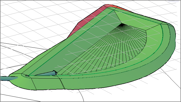
Figure 17-8: A pond design composed of grading objects
Understanding Grading Criteria
The design parameters you apply to a grading object can require multiple pieces of information. For this reason, Civil 3D utilizes a system of grading criteria, which enables you to refer to a set of instructions by name rather than having to re-specify them for each grading design. For example, you might have criteria with the name Curb, which instruct Civil 3D to project upward at a very steep slope for a very short distance. Similar criteria with names like Pond Embankment, Ditch Slope, and so on might be created alongside your Curb criteria. You can organize your named grading criteria even further by grouping them into grading criteria sets. For example, you might have one criteria set for pond grading, another for parking lots, another for athletic fields, and so on. Figure 17-9 shows grading criteria that would be used to create the inside slope of a pond.
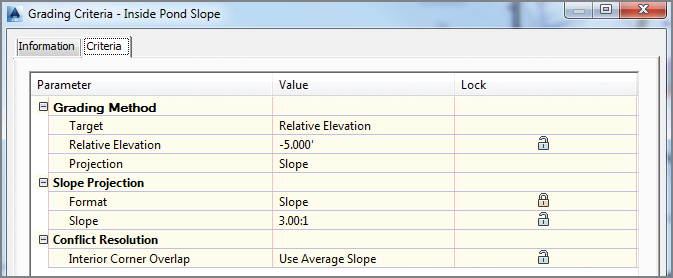
Figure 17-9: An example of grading criteria typically used for the inside slope of a pond
Understanding Grading Groups
A grading group is a named collection of grading objects that enables you to perform certain important functions with multiple grading objects simultaneously. For example, you can create a surface from a grading group or calculate cut and fill values by comparing a grading group to a surface in the drawing.
Understanding Grading Objects and Sites
Like feature lines, grading objects must exist in a Civil 3D site. When two or more grading objects occupy the same site, there is potential for them to interact. There is also the potential for grading objects to interact with other feature lines in the same site. This interaction can benefit some designs, but there are cases where this interaction will cause the design to be incorrect. Therefore, it’s important to proactively manage sites while you’re working with grading objects and feature lines.
Creating Grading Objects
You begin creating a grading object by launching the Grading Creation Tools command. This opens the Grading Creation Tools toolbar (see Figure 17-10), which is similar to the Alignment Layout Tools and the Network Layout Tools toolbars that you used in previous chapters. Like those toolbars, the Grading Creation Tools toolbar provides the commands to configure your design, create new design objects, and edit those objects.
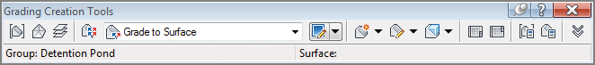
Figure 17-10: The Grading Creation Tools toolbar
Exercise 17.4: Create Grading Objects
In this exercise, you’ll build a pond using grading objects.
- Open the drawing named
Creating Grading Objects.dwglocated in theChapter 17class data folder.The drawing is zoomed in to the proposed location of a stormwater detention pond. You’ll use grading objects to build a model of the pond, starting with the green feature line that represents the top inside edge of the pond.
- On the Home tab of the ribbon, click Grading ⇒ Grading Creation Tools.

- On the Grading Creation Tools toolbar, click Set The Grading Group. Select Pond, and click OK. On the Site dialog, select Pond and click OK.

- On the Create Grading Group dialog, type Pond in the Name field. Verify that Automatic Surface Creation is turned on, and then click OK. Click OK to dismiss the Create Surface dialog box.
- Expand the criteria list, and choose Grade To Relative Elevation, as shown in Figure 17-11.
- Expand the list of creation commands, and click Create Grading, as shown in Figure 17-12.

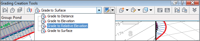
Figure 17-11: Selecting grading criteria on the Grading Creation Tools toolbar
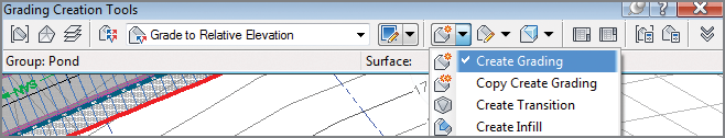
Figure 17-12: Selecting the Create Grading command
- When prompted to select a feature, click the green feature line. When you’re prompted to select the grading side, click a point inside the feature line.
- Press Enter to apply the grading to the entire length.
- When prompted for the relative elevation value, type -7 (-2.13), and press Enter. When you’re prompted for a format, press Enter to accept the default of Slope.
- When you’re prompted for a slope, type 3 and press Enter to apply a slope of 3:1.
After a pause, a new grading object is created that represents the inside slope of the pond. A surface is also created, and it’s displayed as red and blue contours in plan view.

- Expand the list of creation tools, and select Create Infill. Click a point near the center of the pond.
The 3D view now shows that the pond has a bottom.
- Select the Grade To Distance criteria.
- Expand the list of creation tools, and select Create Grading. When you’re prompted to select a feature, click the same green feature line that you picked in step 9.

- When prompted for the grading side, pick a point outside the pond. Press Enter to apply the grading to the entire length.
- Press Enter to accept the default distance of 10.000' (3.000m). When you’re prompted for a format, type G to invoke the Grade option, and press Enter.
- Press Enter to accept the default grade of 2 percent.
- On the Grading Creation Tools toolbar, click Set The Target Surface. In the Select Surface dialog box, select EG and click OK.

- Select the Grade To Surface criteria. Expand the list of creation tools, and select Create Grading.

- Click the outside edge of the grading object created in step 18. Press Enter at all prompts to accept the default values.
This creates a 3:1 daylight slope that intersects with the EG surface. This also completes the surface for the pond, as indicated by the red and blue contours (see Figure 17-13).
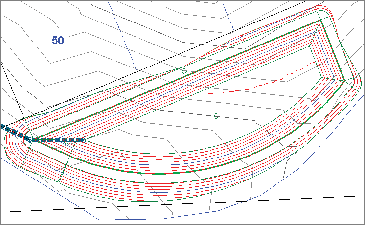
Figure 17-13: Contours representing the pond design
- Save and close the drawing.
You can view the results of successfully completing this exercise by opening Creating Grading Objects - Complete.dwg.
Editing Grading Objects
Because of the dynamic nature of grading objects, any edits to a feature line that serves as a grading-object baseline will automatically trigger an update of the grading object. This makes most grading-object editing fairly easy. In addition, there are two tools you can use to edit the criteria that were used to create the grading object: Grading Editor and Edit Grading. The Grading Editor command opens Panorama, enabling you to edit the criteria in a table format. The Edit Grading command is a command-line interface.
Exercise 17.5: Edit Grading Objects
In this exercise, you’ll edit the pond grading objects that you created in the previous exercise.
- Open the drawing named
Editing Grading Objects.dwglocated in theChapter 17class data folder. - Click the green feature line that represents the inside edge of the pond berm. Click the grip at the northeast corner, and then use the Center object snap to select the center of the red circle to the east.
The grading object recalculates, based on the new shape of its baseline. The grading-group surface also updates, enabling the contours to match the new shape as well.

- With the feature line still selected, click Raise/Lower on the Edit Elevations panel of the ribbon.
You’re prompted to specify an elevation difference.
- Type -1 (-0.3) and press Enter to lower the feature line by 1' (0.3m).
The entire grading group and associated surface update. Now the bottom of the pond is too low and needs to be raised.
- Press Esc to clear the selection of the feature line. On the Modify tab of the ribbon, click Grading.

- Click Grading Editor, and then click a point within the inside embankment of the pond.

The edges of the grading object are highlighted to help you make your selection.
- On the Grading Editor tab of Panorama, type -6 (-1.83) for Relative Elevation, and press Enter.
- On the Grading tab of the ribbon, click Edit Grading. Click a point within the area representing the top of the berm.

- When you’re prompted to specify a distance, type 12 (3.6) and press Enter.
- Press Enter twice to accept the previous settings. Press Enter a third time to end the command.
The grading group and surface update to accommodate the wider berm. The pond model now reflects the wider berm along with the shape and elevation changes made in earlier steps (see Figure 17-14).
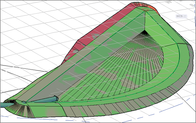
Figure 17-14: The pond model after several edits
- Save and close the drawing.
You can view the results of successfully completing this exercise by opening Editing Grading Objects - Complete.dwg.