EXPERIMENT 8
8.1Object: No-Load Test on a Separately Excited D.C. Generator (Magnetization Characteristic)
8.2Experimental Setup
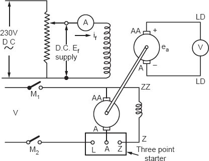
A separately excited D.C. generator coupled mechanically with a motor is used to obtain a magnetization characteristic. The generator is run at rated speed, and the open circuit voltage is measured by a voltmeter. Field current is measured by an ammeter in the separately excited winding of the generator.

Figure 8.1
The ranges of the ammeter and voltmeter will depend on the specifications of the generator. The no-load voltage will go on increasing with field current if and will reach a maximum point and become constant due to saturation. The field current if is increased from zero to some value till ea becomes constant. The if is then decreased and ea is measured correspondingly. The if is brought to zero and ea is noted. Experimental remits are tabulated.

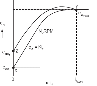
Figure 8.2
This experiment is made to find the voltage induced in the machine. The induced voltage will be
| ea = Kif | (8.1) |
The constant K of the machine can be obtained as follows:

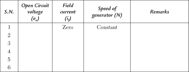
EXPERIMENTAL RESULTS (if increasing)

A graph between if and ea is plotted as shown in Figure 8.2. It is called an initial magnetization curve, from point X and Y. The decrease of voltage ea with if is also plotted to obtain curve YZ.
The magnetization curve is shown in Figure 8.2. The curve XY is called the open circuit characteristic of a separately excited generator.
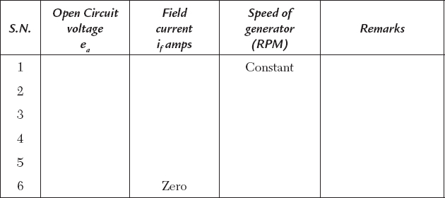
EXPERIMENTAL RESULTS (if decreasing)

8.3Discussion
The experiment is made to find a constant K volts per field ampere for the machine, maximum voltage ea max and the maximum excitation current if max. The YZ curve encloses an area that will give us the hysteresis loss for a half cycle of field current reversal.
8.4Questions and Answers on the Experiment
Q1. What information do we obtain from the magnetization curve?
Ans. A value of generated EMF is obtained at a given field current and speed. The EMF varies with field current if and speed; we have
| ea =Kif, K = ea/if | (8.3) |
K is a constant of machine volts per field amperes. The determination of constant K is obtained. A voltage due to residual flux is also obtained.
Q2. How does the magnetization curve change when we change the speed?
Ans. The curve as a whole rises with the increase of speed and goes down with decrease of speed.
Q3. What factors affect the shape of the magnetization curve?
Ans. The number of turns on poles, size, shape, and materials of the poles, air gap length, and rotor core dimensions and material affect the shape of the magnetization curve.