EXPERIMENT 12
12.1Object: Open-Circuit Test and Short-Circuit Test on a Single-Phase Transformer
12.2Experimental Setup
Open-circuit and short-circuit tests are performed to determine the power losses and the parameters of the transformer. Moreover, the power factor at open-circuit and short-circuit conditions is also an important requirement.
12.2.1Open-Circuit Test
An open-circuit test is performed by applying a full voltage in the transformer at the high voltage side. Power transformers are connected to the high voltage side for the whole time and the low voltage side may create an open circuit for a period. The readings in the wattmeter are read at full voltage.

Figure 12.1
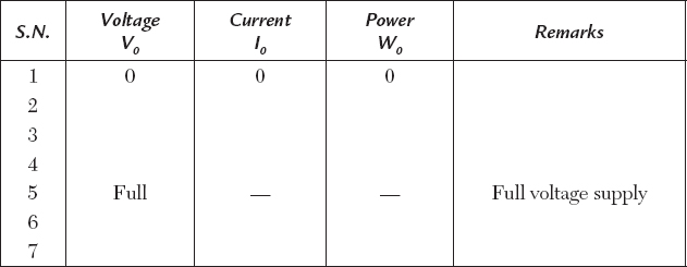
A circuit diagram is shown in Figure 12.1. The readings are tabulated at full voltage. The voltage supply is increased from 0 V to more than full voltage, and wattmeter readings are tabulated.
EXPERIMENTAL RESULTS

If we increase the voltage from 0 V to some value more than full voltage in the primary, we must remember the reading at full voltage and note it in the table at S.N. 5, for example.
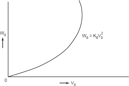
The voltage is increased from the auto-transformer. A graph is plotted between the voltage V0 and power loss W0.
The W0 is called iron loss in the case of the transformer. The graph is shown in Figure 12.2. It may be shown that the iron loss
W0 = K0V02 for the curve,
where K9 is a constant.

Figure 12.2
12.2.2Calculation of Parameters and an Open-Circuit Equivalent Circuit
The power input will be dissipated in the form of loss because there is no output. The W0 will be
| W0 = V0I0 cos ϕ0 | (12.1) |
where cos ϕ0 is the power factor at no-load condition and will be:


Figure 12.3
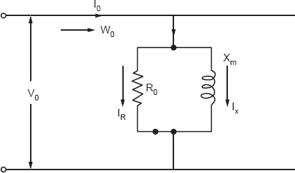
Figure 12.3 will be the equivalent circuit of the transformer at no-load.
The no-load current I0 will be divided into two branches of R0 and Xm, as follows:
| IR = I0 cos ϕ0 | (12.3) |
| IX = I0 sin ϕ0 | (12.4) |
The parameters R0 and Xm will be

12.2.3Discussion on Open Circuits
The open-circuit test itself is a full test and is performed to determine iron loss and the open-circuit equivalent circuit of a transformer. The iron loss W0, equivalent circuit, and no-load power factor are determined.
12.2.4Short-Circuit Test
A short-circuit test is performed to determine copper loss, the short-circuit power factor, and the equivalent circuit at short-circuit conditions.
The experimental circuit is shown in Figure 12.4.

Figure 12.4
A 20% reduced voltage is supplied to the transformer. For example, if full voltage is 230 V, 46 V will be supplied to the transformer. Approximately 50 V will be enough. A full current is adjusted in the ammeter, and the voltage is reduced to about 20%.
Readings in the instruments are observed. The Is, Vs, and Ws are designated for short-circuit current, voltage, and power. The results are tabulated as follows.
EXPERIMENTAL RESULTS

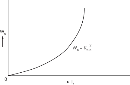
The reading Ws stands for copper loss and varies with the current Is. We plot a graph between current Is and Ws in Figure 12.5.

Figure 12.5
It may be shown that
Ws = KsIs2
where Ks is a constant. The equivalent circuit of the transformer under short-circuit conditions is shown in Figure 12.6.

Figure 12.6
The parameters R and X will be found from simple series circuit principles.


The resistance R and X will be
| R = Z cos ϕ | ||
| X = Z sin ϕ | (12.8) |
12.2.5Discussion
Copper loss, short-circuit power factor, and equivalent circuit under short-circuit conditions are determined as shown previously.
12.3Questions and Answers on the Experiment
Q1. If the O.P. and S.C. tests are made on 60 c/s instead of 50 c/s, what will be the effect?
Ans. The reactance will be high.
Q2. In a short-circuit test a watt meter reads 200 W at a short-circuit of 15 A. What will be the readings of the wattmeter at 30 A of current?
Ans.

Q3. Do O.C. and S.C. tests provide accurate regulation?
Ans. We obtain approximate regulation by a phasor diagram when the impedance is calculated from the two tests.
Q4. How will we calculate efficiency by open-circuit and short-circuit tests?
Ans. The efficiency will be

Pi, iron loss is constant Pc; copper loss determined at a short-circuit current can be multiplied by the square of the load fraction K, where
