EXPERIMENT 19
19.1Object: No-Load Test and Short-Circuit Test on a Three-Phase Alternator
19.2Open-Circuit Test and Short-Circuit Test on a Three-Phase Alternator
An open-circuit test and a short-circuit test are performed on a three-phase alternator to find the synchronous impedance of the alternator. If the resistance of the machine is negligibly small, we determine the reactance, which will be equal to the impedance.
Iron loss and copper loss are determined by these two tests. The open-circuit test will provide us the iron loss while the short-circuit test gives us the copper loss. The open-circuit characteristic and short-circuit characteristic are plotted from the test results.
19.3Experimental Setup
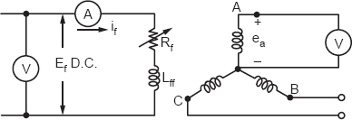
An open-circuit test will require us to run the alternator without load. Full voltage is applied to the D.C. side of the exciter. A voltmeter will be connected in one of the phases.

Figure 19.1
The field current if is varied by Rf, the field rheostat, and various readings of ea are obtained by the voltmeter.
EXPERIMENTAL RESULTS
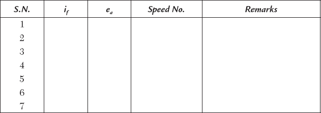
The input to the exciter will be Ef if watts, and this input will be consumed in the iron loss and field copper loss. We call it the no-load loss. The excitation voltage Ef can be varied to obtain the no-load loss in the alternator.
Since there is no current in the armature of the alternator, there is no problem of any loss in this side. The open-circuit characteristic can be plotted between if and ea, the open-circuit voltage in Figure 19.2.
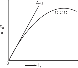
Figure 19.2
19.4Short-Circuit Test
The short-circuit test is performed by connecting ammeters in three phases of the alternator and supplying a reduced voltage in the exciter. Figure 19.3 represents an experimental setup for a short-circuit test. The short-circuit current is read in one of the phases at reduced voltage.
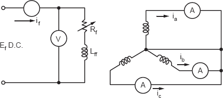
Figure 19.3
EXPERIMENTAL RESULTS
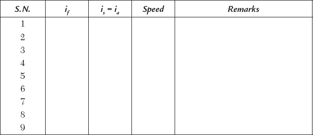
A graph between if and is is plotted, which is called the short-circuit characteristic (S.C.C.).
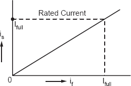
Figure 19.4
The no-load loss and short-circuit loss are plotted for the alternator.
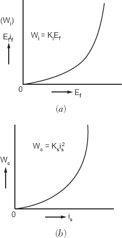
Figure 19.5
19.5Determination of Synchronous Impedance
The synchronous impedance can be calculated from the open-circuit test and short-circuit test. A combined graph is drawn for the O.C. and S.C. tests in Figure 19.6.
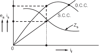
Figure 19.6
The synchronous impedance will be:

The impedance is calculated at every value of if and corresponding ea. The synchronous impedance is also plotted with if. The results are presented in Figure 19.6.
19.6Discussion
The no-load test and short-circuit test are performed to find the synchronous impedance of the generator. The other results that may be obtained by these tests are the no-load loss variation with excitation voltage and the short-circuit loss variation with short-circuit current.
19.7Questions and Answers on the Experiment
Q1. Why is the impedance not constant?
Ans. The impedance varies with the field current. The reactance changes with the flux in the air gap or winding and, therefore, the impedance will change.
Q2. What is a synchronous reactance?
Ans. The synchronous reactance Xs is the reactance at synchronous speed and the field current.
Q3. What is a short-circuit ratio (S.C.R.)?
Ans. The short circuit ratio is:

Q4. What is a synchronous speed?
Ans. The synchronous speed will be:

It is directly proportional to the frequency of the supply and inversely proportional to the number of poles.
Q5. What do you understand by synchronous and synchronism?
Ans. To follow the step-by-step movement of two items. The soldier’s hands and legs are in synchronism. When they move they make a left-right. If one of the hands or legs is out of order, the entire group will lose synchronism.
Similarly, the synchronous motor or generator has a field and rotor moving in synchronism. If there are n-machines the problem of synchronism will be analogous to the soldier’s left-right