EXPERIMENT 20
20.1Object: A Load Test on a Three-Phase Synchronous Generator
20.2Regulation by an Actual Load Test
A load test on a three-phase synchronous generator is performed to determine the regulation at a given power factor and the terminal voltage. This method is called regulation by actual load test.
The test is simple. We run the alternator at no load and adjust the field current to obtain a no-load voltage Ea, which is measured by a voltmeter. When load is applied the Ea will change. The Ea will be obtained at the given voltage and power factor.

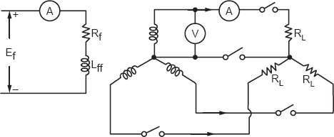
Figure 20.1
20.3Experimental Setup
We read the specifications of the drive of the generator, and the nameplates are noted. Determine the range of the instruments. A voltmeter and ammeter will be required in the load circuit and the same for the field circuit. We read the ammeter and voltmeter when the load is switched. The load may be three lamps or six lamps connected in each phase. Four lamps connected in each phase is shown in Figure 20.2.

Figure 20.2
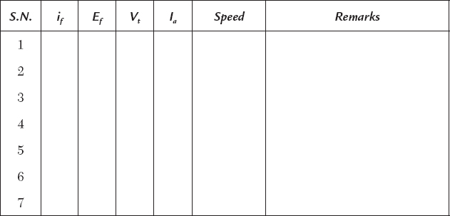
The experimental results are tabulated for every lamp switching. Let the transient decay and then read the instruments under a steady state.
EXPERIMENTAL RESULTS
20.4A Load Characteristic of the Alternator
A load characteristic of the alternator may be plotted as given in Figure 20.3. The load or V-I curve is not unique but has different forms depending on the power factor of the loads.
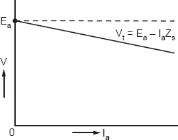
Figure 20.3
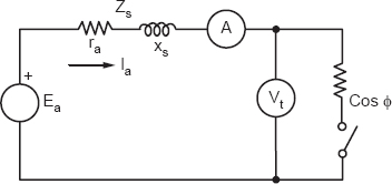
Figure 20.4
The voltage Ea at a particular load will be different from the no-load voltage. The EMF can be determined from a phasor diagram and an equivalent circuit shown in Figures 20.4 and 20.5.
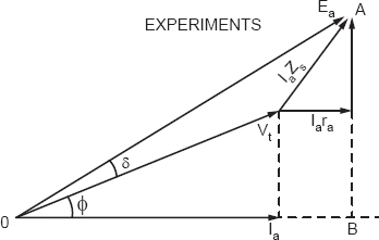
Figure 20.5
The Ea will be (from triangle OAB):
Ea2 = (Vt cos ϕ + Iara)2 + (Vt sin ϕ + IaXs)2
As a matter of fact, we may read Ea from the triangle OAB and the power angle δ.
20.5Regulation
The regulation will be obtained as follows:

20.6Discussion
A load test is performed on an alternator to determine the regulation and V-I characteristics. Whenever we specify the regulation, the V-I curve is not as important. As a matter of fact, the regulation is one from of the V-I curves.
Determining the regulation is our objective, but to draw the V-I curve will be an additional result.
20.7Questions and Answers on the Experiment
Q1. What is load?
Ans. The load is a current taken by a device. Most often the load means the load impedance of the device. The lamp will be a load. It may either be specified by the current or impedance. A 100-watt lamp will take a current of 46 mA at 220 V and will be specified by an impedance of 484 Ω.
The load will be either 484 Ω or 46 mA. For simplicity we specify the current as the load.
Q2. How do you connect single-phase loads to the three-phase generator to maintain the balance?
Ans. We connect the loads in alternate phases turn by turn.