EXPERIMENT 23
23.1Object: To Determine Regulation of a Three-Phase Alternator for Full Load at a Power Factor Using the Zero Power Factor Method or the Potier Triangle Method
23.2This Test Requires an Open-Circuit Characteristic and a Zero Power Factor Load Test on the Alternator
Zero power factor loads are synchronous motors for the reactors. We use three reactors for the Z.P.F. (zero power factor) load.

Figure 23.1

Figure 23.2
A zero power factor curve is drawn between the field current if and the voltage on the terminals, V.
23.3Experimental Setup
A circuit diagram for the Z.P.F. test is represented in Figures 23.1 and 23.2. Open-circuit and Z.P.F. tests are performed one by one as follows:
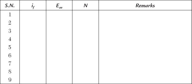
EXPERIMENTAL RESULTS 1

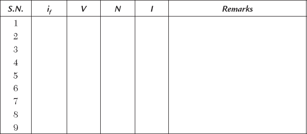
Readings of experimental results are entered into two tables. The speed in the open-circuit test is kept constant equal to the full speed. However, this is a synchronous machine.
EXPERIMENTAL RESULTS 2

The speed will remain constant at the synchronous speed.

Figure 23.3
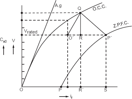
The O.C.C. and Z.P.F. curves are drawn in Figure 23.3. The air gap line A-g is drawn tangent to the O.C.C. OP is the exciting current corresponding and the full-load, short-circuit current. Draw OʹPʹ and mark the point Pʹ′. Draw O′P′ between the two curves such that O′P′ equals OP. Draw a parallel line O′Q to the A·g line and mark the point Q on the O.C.C. Join QP′ and draw a perpendicular line from Q to R and mark the QR line.
The QR will give the leakage reactance drop (IXL). O′R will be the exciting current required to overcome the leakage reactance drop, and RP′ will be the exciting current to overcome the armature reaction effect at rated current.
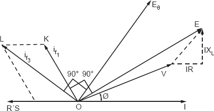
A phasor diagram will be drawn to determine the E0 required to calculate the regulation at a power factor ϕ. E is the induced voltage when the armature reaction is neglected, and V is the terminal voltage, IXL; leakage reactance drop IR; is the resistance drop. From the O.C.C. corresponding to the induced voltage E, OK is the

Figure 23.4
exciting current required to produce flux for the induction of E. The if1 leads the E by 90°. R’S or R’P is the exciting current to overcome the armature reaction. This current if2 will be in phase opposition to the current I. R’S = if2 required to overcome the armature reaction.
A sum of if1 and if2 will be if3 which will be represented by OL. if3 will be the total exciting current required to produce rated voltage and the given power factor. From the O.C.C. find the Eo corresponding to OL or if3. In this way the Eo is found and used in the regulation calculation.

Figure 23.5
Thus, the regulation will be:

23.4Discussion
The zero power factor method is used to find the regulation of an alternator. Most often the alternator problems are serious at zero power factor loads. Zero power factor means inductive loads like reactors, synchronous motors, and inductors.
23.5Questions and Answers on the Experiment
Q1. Why do we use the Potier triangle method for regulation?
Ans. The effect of armature reaction and leakage reactance is taken into account, while in the simple method, these two factors are ignored.
Q2. Why do we call it the zero power factor method?
Ans. We use a load of zero power factor.
Q3. What are the loads which have a zero power factor?
Ans. Synchronous motors, reactor coils, autotransformers, mutual inductors, and so forth.
Q4. Is the power factor zero for these loads? Why?
Ans. No, the p.f. is nearly zero. It may be 0.2 or 0.1 in value, and as compared to 1, it may be assumed as zero.