EXPERIMENT 31
31.1Object: For the Given Current Transformer and Burden to Find the Ratio and Phase Angle Error at
(a)100% Rated Current and
(b)50% Rated Current by the Mutual Inductance (Absolute) Method
31.2A Current Transformer Is a Current Operated Device as an Ammeter
A current transformer is a current operated device as an ammeter and, therefore, it has to be connected to a current source. If it is connected to a voltage source, it must be connected in series with a fairly high impedance.
31.3The C.T. Testing Apparatus
This consists of a number of primary shunts (non-inductive heavy current resistance) immersed in an oil-filled tank. The tank can be water cooled. Motor driven stirrers along with a thermo-switch are also provided for further cooling.
The primary shunts are provided with one negative and two positive buses. Only the negative and lower positive bus are used. The second positive bus is provided to facilitate the testing of the shunts. Any suitable shunt may be chosen and can be connected to the lower positive bus bar through the connecting block.

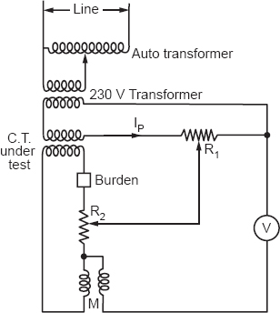
Figure 31.1
Observations

Calculations
For 100 % rated current
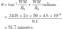
Phase angle error
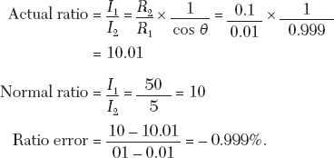
Ratio Error
Galvanometer. A vibration galvanometer is required to obtain the null point since the voltage drops to be balanced are very small. The accuracy of the experiment will depend upon the sensitivity of the galvanometer. In fact, the null position may not be obtained at all if the galvanometer is not sensitive enough to detect the unbalanced voltage in the circuit.
Apparatus. Current transformer, burden, resistance, shunt, and mutual inductance.
Procedure. Make connections as shown. Adjust the current in the primary circuit of the C.T. (under test) to 100% rated current. Obtain the null point by varying R2 and M. Note the corresponding readings. Similarly, adjusting the current in the primary circuit to 50% rated current again obtains the null point, and note the values of R2 and M.
Calculations
Phase angle error

For 50% rated current
Phase angle error

The ratio error will be the same.

Also

Results: For the given current transformer and burden the ratio error
and phase angle error for 100% rated current = 51°7’
and for 50% rated current = 1°
31.4 Questions and Answers on the Experiment
Q1. What are the factors on which the ratio and the phase angle error depend? How are they minimized?
Ans. A phase angle error of 0 C.T. depends on:
1.There is a difference in the current ratio and turns ratio. It depends on the magnitude of the exciting current of the transformer, and the secondary current and point of the secondary circuit. This error comes into consideration in the current measurement; it is necessary that the secondary current shall be displaced by the primary current by 180° The C.T. has a phase angle error ϕ. The phase angle error depends upon the value of the magnetizing current component Im.
In order that the number of exciting ampere turns I0 Tp shall be a small proportion of the total primary ampere turns, we take a single bar as a primary. Now to get high ampere turns of the order of 500 to 1000, the current should be very high. Metals or alloys of high permeability and loss can be used for the core, for example, Ma metal for as low as 100 A with good performance.
The winding should be close together in order to reduce the secondary leakage reactance, as this increases the ratio error. The ratio error is made less positive as the power factor is reduced. Also, the phase angle error is obviously reduced with reduction of power, since n s moves more into phase with I0 as it is increased.
Q2. Why can’t the secondary circuit of the current transformer be left open circuited?
Ans. The number of primary ampere turns is a fixed quantity if the primary current is fixed. If, therefore, a C.T. has its secondary terminals open when current is flowing in the primary, a very high flux density is produced in the core owing to the absence of back EMF. The ampere turns due to the current in the secondary winding with consequent operate. Also, when high magnetizing forces are suddenly removed from the core, they leave behind a considerable residual magnetization in the core, causing an appreciable change in the ratio and phase angle error.
Q3. Give the vector diagram of a C.T. operating at a:
(i)purely resistive load
(ii)purely reactive load.
Ans. where,

Rs = Resistance of secondary winding
Ks = Reactance of secondary winding
Es = Secondary induced voltage
Tp = No. of primary turns
Ts = No. of secondary turns
Vs = Secondary terminal volume
Is = Secondary current
Is = Primary current
θ = Phase angle of C.T.
δ = Phase angle of burden
α = Angle between Io and ϕ
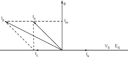
Figure 31.2
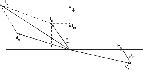
Figure 31.3
Q4. If an air gap is cut in the core of a C.T., how will its performance change?
Ans. If an air gap is cut in the core of a C.T., the reluctance of the air path as well as the magnetic path will increase considerably. This will require a large amount of exciting current. A large exciting current will make the actual ratio more than the nominal ratio and will also increase the phase angle error, which directly depends upon magnetizing current.
If we neglect the angle δ the angle between the secondary current and secondary induced voltage, which is fairly small compared to the phase angle, then:

Q5. What are the materials used for the core of the current transformer?
Ans. To minimize the ampere turns required, the core must have a low reluctance, small iron loss, and the flux density used in core should be small, not greater than 1000 lines/cm2. Ma metal, a nickel iron alloy containing copper, has the properties of very high permeability, low loss, and small retentivity. All of which are advantageous for C.T. But it has a disadvantage in that its maximum permeability (about 90,000) occurs with a flux density of about 3500 lines/cm2. Silicon steel is the other material with a maximum permeability of about 4500 at 5000 lines/cm2.
The alloy permendur (45% iron, 45% cobalt, and 2% vanadium) has a very high saturation point. Mostly mu metal is used for the core. The other materials used are hot rolled silicon, iron, cold rolled silicon, silicon iron, 36/64 alloy, ratio metal, special ratio metal, and mu metal.
Q6. What is the utility of this experiment?
Ans. The ratio and phase angle error of the current transformer should be determined with great accuracy, because C.T.s are used in relays. Errors of a C.T. should be correctly known.