
QUESTIONS AND ANSWERS IN ELECTRICAL ENGINEERING
Q1. What is the life of an electric lamp?
Ans. The life of an electric lamp is 1000 hours of burning. A fluorescent lamp (tube light) has a life of 3000 hours of burning.
Q2. What is the resistance of human body?
Ans. The resistance of the human body in dry conditions is 10,000 ohms and 1,000 ohms in wet conditions.
Q3. Why do we connect electric equipment to earth?
Ans. A dead part of a piece of equipment is connected to earth for a safety of the human body and animals. The dead part is the part which does not have a current. When a live part (current-carrying part) unfortunately touches the dead part, a current will go to earth and the human body will be safe.
Q4. Why does the human body feel a shock when a voltage is touched to the body?
Ans. A shock is felt due to the wear and tear of the muscles. A current flows through the body. The resistance of a body is 10,000 ohms. If a voltage of 220 volts is caught by a hand, a current of 220 mA will flow. A current of 22 mA is fatal for the body. If the body is dry, a resistance will be 10,000 ohms and the current through the body will be 22 mA. A death will occur whether the body is dry or wet.
Q5. Which are more dangerous, D.C. shocks or A.C. shocks? Why?
Ans. A.C. shocks are more dangerous than D.C. shocks. This is due to more wear and tear in the body. The frequency of A.C. current damages the body more than D.C.
Q6. What is the resistivity of the earth?
Ans. The resistivity of the earth varies from 100 ohms to 10,000 ohms. The resistivity will depend on the type of soil.
Q7. A 1000-watt heater has a wire length of 50 meters. If we use a half-length of 25 meters, what will be the capacity of the heater?
Ans. The capacity will be 2000 watts when we use a half-length of wire of 25 meters.
Q8. Explain fully why the capacity of the heater is doubled when we use the half-length of wire.
Ans. The power is given by

where V is voltage and R is resistance. The resistance will be half (R/2). Therefore,

If W1 = 1000 W, then W2 = 2 × 1000 = 2000 W.
Q9. Which one electric lamp has more resistance when a 100-watt lamp and a 60-watt lamp are given?
Ans. The 60-watt lamp has more resistance than a 100-watt lamp.
Q10. What will be the resistances of a 100-watt lamp and a 60-watt lamp?
Ans. The resistance of the lamps when used for a 230-volt supply will be

The resistance of a 60-watt lamp will be

Q11. Why are D.G. series motors not started at no-load?
Ans. The series motors are not started at no-load because the speed at no-load will be infinitely high. The shaft of the motor will fly away and an accident might be caused.
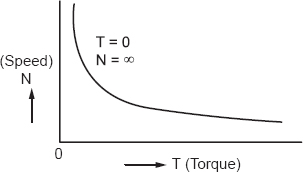
Figure 11.1
It is always advisable to load the motor before starting it.
Q12. Why is a current transformer not kept open circuited?
Ans. A current transformer is never kept open circuited when it is connected in the circuit, because the primary winding has one turn and the secondary has many number of turns. A high voltage will be induced in the large number of turns and it will cause a shock to the worker. Therefore, keep the current transformer connected with secondary winding. High current in the primary causes insulation damage.
Q13. What is a transducer?
Ans. A transducer is an energy converter; electrical machines are the transducers.
Q14. What are material transducers?
Ans. Material transducers are formed using materials such as ferro electric materials, piezoelectric materials, magnetostrictive materials, and so on. The materials convert one energy form to the other. Electro-mechanical energy conversion is possible with the help of material transducers.
Q15. Can a D.C. series motor also run on A.C. supply?
Ans. Yes, a D.C. series motor can also run on A.C. supply. The example is A.C. series motors, called universal motors.
Q16. Why is shunt field winding made of thinner wire and why does it have a large number of turns, whereas series field winding is thicker and has fewer turns?
Ans. This is made because high resistance may be obtained in the shunt winding and low resistance in the series field winding.
Q17. Why is the speed of a D.C. series motor not controlled by connecting a variable resistance in series with the armature?
Ans. The power loss will be high and power input to the armature will be very small.
Q18. Is the voltage drop in a D.C. shunt generator with load more as compared to a separately excited D.C. generator?
Ans. There is no effect on the voltage drop. The voltage drop will remain the same in both the cases.
Q19. Why is the D.C. series motor suitable for traction purposes?
Ans. The high speed in the starting and direction can be changed by reversing the current.
Q20. A rotating shunt generator is not developing voltage between its terminals. What would be a reason?
Ans. Shunt field rheostat resistance may be more than the critical resistance for the machine.
Q21. How will you obtain linear commutation in a D.C. machine? Name methods.
Ans. We use interpoles to reduce the induced voltage in the coil undergoing commutation.
The inductance of the coil should be zero, so that current cannot be retarded.
Q22. What type of power transformer at a generating station for bulk power transfer is used? Whether step up, step down, or 1:1 ratio?
Ans. Step up transformer.
Q23. Transformers are usually of what type of distribution? Whether step down, step-up, or 1:1 ratio.
Ans. Step down.
Q24. Does the efficiency of the transformer depend on load current?
Ans. Yes, the efficiency increases with load current and reaches to maximum value and then decreases with load current.
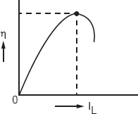
Figure 24.1
Q25. How many type of magnets are there? Which type of magnet is used for lifting load?
Ans. There are two type of magnets; one is an electromagnet and the other a permanent magnet. Permanent magnets are used for lifting the loads of iron materials.
Q26. At what speed reluctance does a motor produces average torque?
Ans. At a specific speed.
Q27. Why do we connect a lamp in the neutral wire and switch in the phase wire?
Ans. If we touch the lamp it will not give shock when connected in the neutral. If we connect the lamp in phase it will give a shock when we change it. If the switch is connected in phase, it does not give a shock because it is insulated.
Q28. Make a circuit diagram of a house wiring with three lamps and three switches.
Ans. The diagram is shown in Figure 28.1. The switch has two points and the lamp has also two points which are connected as shown in the diagram.
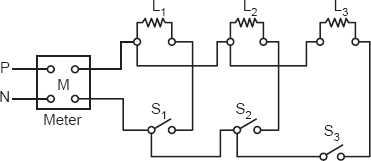
Figure 28.1
L1, L2, L3 are the lamps and S1, S2, S3 are switches.
Q29. Why do we prefer the magnetic field in an electromechanical energy converter over an electric field?
Ans. The production of an electrostatic field will require a large air gap as compared to the electromagnetic field. The size of the machine will be very large if the electric field is produced.
Q30. How many parallel paths are used in a wave connected armature winding?
Ans. Two parallel paths.
Q31. How many parallel paths are used in a lap connected armature winding?
Ans. Parallel paths are equal to the number of poles used in the lap winding.
Q32. What will happen to the speed of shunt motor, if the polarity of D.C. supply to its terminals is changed?
Ans. The speed will remain the same in RPM and direction. The change of polarity of the D.C. shunt motor does not affect the speed direction.
Q33. What will be the magnitude of induced voltage of a D.C. shunt generator when the shunt field resistance is decreased?
Ans. The voltage will increase in magnitude because the field current will increase:
| Ea | = Kif, | |
| where | Ea | = induced voltage |
| K | = constant and | |
| if | = field current. |
Q34. What will happen to the speed of a series motor when the number of turns in its field winding is decreased?
Ans. The speed of the D.C. series motor will increase.
Q35. How will you connect the compensating winding? Either in parallel or in series.
Ans. In series with the armature.
Q36. What is the inductance of a magnetic circuit?
Ans. The inductance of a magnetic circuit is the rate of change of flux with respect to current.

If there are N number of turns, we have

Q37. What is a physical inductance? How does physical inductance differ from the effective inductance? What is the effective inductance?
Ans. The physical inductance is found from the configuration of a magnetic circuit

| where | L | = inductance in Henrys |
| N | = number of turns | |
| μo | = 4π × 10– 7 H/m | |
| μr | = relative permeability | |
| A | = area of cross-section, m2 | |
| Lm | = mean length of magnetic path. |
The effective inductance is obtained from a voltage induced or current:
 | |
| or |  |
| or |  |
The two inductances may differ in a slight numerical values due to measurement errors.
Q38. What is a physical resistance? What is an effective resistance? How does physical resistance differ from the effective resistance?
Ans. The physical resistance is directly proportional to the length of a wire and inversely proportional to the area of cross-section
 | |
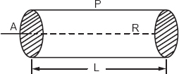 | |
| Figure 38.1 | |
| where | R = resistance |
| P = constant of proportionality | |
| L = length in meters and | |
| A = area of cross-section, m2. |
The effective resistance will be given by the measurement of voltage and currrent.
| R = V/I |
These two may differ due to temperature and measurement errors.
Q39. What is a physical capacitance? Define effective capacitance and point out differences between these two.
Ans. Physical capacitance is determined from the physical configuration of a capacitor with its dielectric
 | |
| where | C = Capacitance in Farad. |
| C = Capacitance in Farad. | |
| εo = Permittivity of vacuum, F/m. | |
| εr = Relative permittivity. | |
| A = Area of plate. | |
| d = Separation between the plates. | |
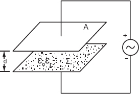 | |
| Figure 39.1 |
The effective capacitance is determined by the measurement of current and voltage

The charge on the plate will be
Q = CV
Or

The two capacitances must be equivalent if they differ, this is due to the measurement errors.
Q40. Why we do use insulators on the poles of a telephone line and electric line?
Ans. The poles are earthed and the conductor carrying current will be in the contact to the ground, and a short-circuit will take place if there is no insulator. The insulator separates the conductor from the ground and confines the current in the conductor path. Both telephone lines and electric lines are insulated through the insulators.
Q41. Which material is used to make the line insulators?
Ans. Porcelain material is used to make the insulators.
Q42. Which material is used to make the switches of house wiring?
Ans. Bakelite material is used to make the switches used in house wire.
Q43. In what manner are electric lamps connected? (Either in series or in parallel.)
Ans. Electric lamps are connected in parallel.
Q44. Which type of lamp has a higher life?
Ans. A fluorescent lamp (tube light) has higher life than the ordinary lamp. Tube light works well up to 3000 hours while an ordinary lamp works for 1000 hours.
Q45. Why we do use a choke and starter in tube light connections?
Ans. The choke and the starter are used to start the tube light burning. The starter gives a switching action to the choke to produce a voltage of the order of 1000 volt.

The supply voltage of 230 V and 1000 V induced in the choke will start the tube light burning.
Q46. What is the direction of electromagnetic torque produced in the generator with reference to the rotation of the rotor?
Ans. Opposite direction.
Q47. Why do we install the motors and generators on a foundation base?
Ans. The action and reaction are equal and opposite. We apply an action of prime-mover force to a generator. The generator produces the internal torque on the forces. The internal forces working on the stator do not take part in the effective motion. The stator forces require the fixation of the stator body, otherwise the machine will fly away.
Q48. In a 230/110 V transformer a 230 V D.C. supply is given. Will the transformer produce 110 V D.C.?
Ans. No, the transformer will be burned due to a very high current flow. There will be no voltage induced to oppose the 230 volt D.C. The resistance of the transformer is very small of the order of 0.1 ohms. A current of 2300 A will flow, which will burn the insulation of wires and the winding.
Q49. Explain how a current in the secondary side increases when load is switched on a transformer?
Ans. The increment of current in the secondary side of a transformer is taken from the primary source of power. Its mechanism is simple. Let a demand of current be I2 in the secondary side. This demand will disturb the steady state working of the transformer. The flux due to this current will increase the increment of flux in the primary winding. The voltage will be decreased. The source voltage will inject the equivalent current from the source of power.
Q50. Why does a transformer on a substation hum?
Ans. A transformer has humming (making a noise) due to air pockets in the core. If a core of a transformer is loose in packing, the stampings will make a noise due to vibrations. The core is formed by packing the laminations which are varnished. There is every possibility of air existence between two laminations. The magnetic stresses will act in the air to vibrate the laminations. This makes the humming in a transformer.
Q51. How will you determine the windage and friction losses in a motor working on electric supply?
Ans. The determination of friction and windage loss is a complicated problem. We may determine it with a simple method. Let the motor run at no-load. Use a shunt motor or induction motor. Do not use the series motor. Go on reducing the supply voltage slowly. The motor will stop at a certain voltage and current. Note the voltage and current. The product of voltage, V and current, I will be the power input to the motor. This input power is consumed in the windage and friction losses. Thus, we determine the windage and friction loss in the motor. This experiment may be made on both D.C. and A.C. motors.
Q52. What is iron loss?
Ans. Iron loss is a power loss in the iron core of a machine. Iron core has a resistance and a path to flow eddy currents. The hysteresis and eddy current loss of power is termed the iron loss. It is called iron loss conventionally because it is dissipated in the iron material. If we use a core of ferrite, even then the loss will be termed iron loss. Most suitable it is called core-loss. It may be energy or power, depending on the calculations.
Q53. What is no-load loss?
Ans. The no-load loss of power occurs at the zero load. This is due to the voltage of the supply available to the machine. The magnetic parts are excited at no-load and the power I2R is dissipated in the iron parts.

Figure 53.1
The load loss is also due to the windage and friction in the rotating machines. Therefore, the no-load will be
No-load loss = Iron loss + Friction loss + Windage loss.
The loss varies with the voltage, V as shown in Figure 53.1.
The load loss W0 varies,
W0 = K0 V02 watts.
Q54. What is copper loss?
Ans. The copper loss of power is dissipated in a winding of a machine. There is a physical resistance of the winding. This will cause a loss of power I2R watts, when current, I flows through it. This is termed copper loss conventionally because windings of copper materials are used. If we use a winding of aluminum wire, the loss of power will be called copper loss and not aluminum loss. The conventional name is well recognized. If the windings are used with a resistance wire of nickel, chromium, and iron, the loss will be still called copper loss. Most suitably this loss is called winding loss and the wires are called winding wires.
Q55. How will you recognize a D.C. fan and an A.C. fan when these are running?
Ans. The D.C. fan has a bottom part which moves with the blades of the fan. In the A.C. fan the bottom part does not move and remains fixed. If you are in a train, observe the fan. This is a D.C. shunt motor. The bottom part rotates with the blades of the fan. If you are in an office, observe the A.C. fan; it does not have a moving part in the bottom.
This is due to the commutator used in a D.C. fan.
Q56. Why do we use a starter for a motor?
Ans. A starter is used to control the input current in a motor. A high current should not be given in the motor. Back EMF in the motor develops slowly in the starting process. If we supply 230 volts suddenly to the motor, without a presence of back EMF, an enormously high current will flow. This will cause the motor to burn.
Q57. Where will you use a three-point starter? Name three points. Make a simple diagram.
Ans. We will use three-point starter for a shunt motor. The three points are L, A, Z, as shown in Figure 57.1.
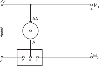
Figure 57.1
Q58. A 100 kW, 230 volt, 1200 RPM generator has a connected load of 50 kW. How much power is generated by the generator? If we connect two loads on the generator, consuming power 50 kW and 50 kW in parallel, how much power will the generator generate? If a 50 kW load is off, how much power will the generator generate? Where has the power gone?
Ans. 50 kW equal to the connected load. At 100 kW, the sum of the power of connected loads will be generated. The power cut has gone in saving the fuel at the prime mover side.
Q59. Why do we use a current transformer with a wattmeter when performing a short-circuit test on a transformer?
Ans. Wattmeter current coil capacity is about 5 amps and, therefore, more current will cause a damage to the coil. In the short-circuit test a current of more than 5 A flows. For the safety of the current coil of a wattmeter, we use a current transformer.
Q60. Make a neat diagram to connect a current transformer with a wattmeter.
Ans. Figure 60.1 represents a neat diagram of a C.T. with a wattmeter.
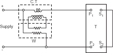
Figure 60.1
Q61. Where will you use the D.C. series motor?
Ans. D.C. series motors may be used for cranes and hoists. Digging, cutting, and punching machines have series motors. Traction motors are series motors.
Q62. Where are the shunt motors used?
Ans. D.C. fans, paper mills, cloth mills, and rolling mills have shunt motors which move the rollers. The fans in trains have shunt motors.
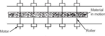
Figure 62.1
Q63. How will you perform a short-circuit test on a single-phase transformer?
Ans. We will supply a 20% approx. reduced voltage to the transformer and note the current and power input. If voltage is 230 volts, supply 46 volts or 50 volts and read current and wattage. This will be a short-circuit test.
Q64. Which type of power loss do you measure by performing a short-circuit test?
Ans. We measure copper loss.
Q65. At what current is this copper loss determined? What will be the copper loss at half the load? If the copper loss is 40 watts at 10 A of current, what will it be at 5 A?
Ans. At the full load, one quarter of the full load copper loss–10 watts.
Q66. How will you perform a no-load test on a transformer?
Ans. We will supply a full voltage and keep the other winding open and then read the current and watts in the instruments.
Q67. Which type of power loss do you measure by the open-circuit test?
Ans. We measure the iron loss at the full voltage.
Q68. At what voltage this iron loss is determined? What will be the iron loss at the half voltage? If the iron loss is 80 watts at 230 volts of supply voltage, what will it be at 115 volts?
Ans. At the full voltage, one quarter of the full voltage iron loss—20 watts.
Q69. How does copper loss vary with the current? How does iron loss vary with the voltage? Make their graphs.
Ans. The copper loss varies as the square of the current and the iron loss as the square of the voltage.
| Wc = KcI2 | |
| and | Wi = KiVo2 |
where Wc—copper loss; Kc—constant; I—current; Wi—iron loss; Ki—constant, and Vo—open circuit voltage.
The graphs are shown in Figures 69.1 and 69.2.
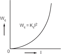
Figure 69.1
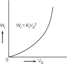
Figure 69.2
Q70. The iron loss takes place for 24 hours in a transformer, why?
Ans. The primary winding of the transformer is connected to the voltage supply for 24 hours. The secondary side may be open for a short time, but the primary winding has supply for 24 hours in a day.
Q71. We make the core of a transformer with laminations (stampings) which are varnished, why?
Ans. To reduce the iron loss the eddy current loss is reduced. The path of eddy currents is broken by the varnish insulation and thus reduces the loss.
Q72. What is a difference between a current transformer and a voltage transformer?
Ans. If the secondary of the current transformer is open, it will be working as a potential transformer. The primary of the C.T. has only one turn while there are many turns in the P.T. The primary of the C.T. is connected in series with the load, while that of the P.T. is parallel to the load. A schematic diagram is shown in Figure 72.1.
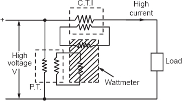
Figure 72.1
Q73. Which material is used to make a core of a current transformer and why?
Ans. Mu metal is used to make a core of the current transformer. The permeability of the Mu metal is very high of the order of tens of thousands.
Q74. Why do we use only one turn in the primary of the current transformer? Why is the turn chosen very thick?
Ans. We choose one turn winding because the induced voltage must be zero, so that the load voltage may not be reduced. A thick conductor is selected to obtain zero resistance, so that the voltage drop may be zero. One turn has another reason of current ratio. There is a large current in the primary and a small one in the secondary. The secondary turns will be smaller if we choose the primary turn.
 | |
| If I2 = 5, I1 = 100, N1 = 1, then | |
 | |
| If we choose N1 = 1, then N2 = 40. | |
Q75. What are the applications of a current transformer?
Ans. A current transformer is used with a relay winding to supply 5 amps of current from the line current which is very high.
A current transformer is used with a current coil of a wattmeter where a power of high current is to be measured.
A current transformer is used as a current source to generate a high current from 5 amps of current. For example, we have a C.T. of ratio 100:5. If we supply 5 amps of current in the secondary, we obtain 100 amps in the primary.
Q76. Why are current transformers and potential transformers called instrument transformers?
Ans. Because these transformers are used with instruments to extend the range. Whenever the power measurement is made in high voltage and high current lines, these C.T. and P.T. must be used with energy meters.
Q77. How will you determine the ranges of an ammeter, a voltmeter, and a wattmeter when you perform an experiment on a machine?
Ans. We read the nameplate of the machine and find the rated current, voltage, and power output. If the current rating is 20 amps, an ammeter of 0–25 amperes will be required. If the voltage is 230 volts, a voltmeter of 0–300 will be needed. If the power output rating is 4.6 kW, a wattmeter of rating 0.5 kW will be sufficient.
Q78. What is creeping error in an energy meter?
Ans. The disc of an energy meter moves when there is no load. This is due to the voltage applied on the voltage coil of the energy meter. It is not possible to disconnect the voltage coil from the supply and the creeping of the energy meter cannot be avoided. If the voltage rises due to certain reasons, the disc will move more. Sometimes it is noted that the disc is making a complete rotation in the same time period.
Q79. What are the differences between an energy meter and a wattmeter?
Ans. The energy meter has a gear system and a mechanism to record the RPM. In the wattmeter there is a spring control in the needle.
Q80. Why do we use a disc in the induction type of instrument?
Ans. Induction principle requires an interaction of two fluxes in the aluminum disc to produce a torque. Ammeter, voltmeter, wattmeter, and energy meters of an induction type are provided with an aluminum disc in which the eddy currents of two types interact to produce a moment to rotate the disc.
Q81. On what factors does the magnetizing MMF of a transformer depend?
Ans. Core dimensions, permeability, primary voltage, and number of turns.
Q82. What is a magnetizing inductance of a transformer?
Ans. The magnetizing inductance of a transformer is due to the core flux and the number of turns. The rate of change of core flux with respect to the current is called the magnetizing inductance.
Q83. What is a leakage inductance of a transformer?
Ans. The leakage inductance is due to the leakage flux. The rate of change of leakage flux with respect to current is called the leakage inductance.
Q84. Name the factors on which the efficiency of a power transformer depends.
Ans. The power factor of the load and the percentage of load.
Q85. What is a skin effect in a wire?
Ans. A current flow on the skin of a conductor is more than the current flow in the center. This is because the frequency and the inductance of the core of conductor are higher than the skin. A low reactance is offered by the skin while it is higher by the center core.
Q86. What is the proximity effect?
Ans. The effect of the current of the side by the conductor is called the proximity effect. The flux of the side by the conductor reduces the flux in one-half and increases the other half.
Q87. What is linkage? What is the relation between linkage and the voltage?
Ans. The product of flux and number of turns is called linkage. The voltage is obtained by the rate of change of linkage per second.
Q88. If there are 10 turns and 10 lines of flux, what will be the value of linkage? If the 100 lines change to 80 lines in 0.10 second, what will be the voltage induced?
Ans. The linkage ψ = Nϕ
= 10 × 10 = 100 turn.maxwell
The voltage

The volts will be e = 2000 × 10−8 volts
As 108 maxwell = 1 weber.
Q89. What is a law of induction?
Ans. The Faraday’s law of induction is stated that:
The induced voltage in a coil is given by the rate of change of flux per second:

Q90. What is a law of interaction?
Ans. The law of interaction gives us a force produced by a current in a magnetic field. The force produced by a current in a magnetic field on a conductor will be:
F = BLI sin α
where F—Force, B—Flux density, L—length, and I—current, α—angle the axes of current and flux.
Q91. In the light of induction and interaction, state that it is impossible to generate a direct current power using electromagnetic devices.
Ans. Induction is made through dϕ/dt if ϕ is constant the dϕ/dt will be zero and, therefore, the D.C. voltage cannot be generated by the electromagnetic devices.
Q92. Why is the disc of an induction instrument made of non-magnetic material?
Ans. To reduce the attraction force on the disc. If we choose magnetic material disc a force of attraction will be more than the force of interaction or torque.
Q93. Why is an induction cup type structure superior to the disc type structure in relays?
Ans. Because it has a lower moment of inertia and a better magnetic circuit.
Q94. What is a power factor of an ideal dielectric material?
Ans. Ideal dielectric has a zero-power factor.
Q95. What is a power factor of an ideal choke coil?
Ans. Ideal choke coil has a zero-power factor.
Q96. What is a power factor of an electric lamp?
Ans. Electric lamp of ordinary nature has 0.98 power factor which is assumed to be unity. Tube light has 0.6 power factor.
Q97. What is the specified power factor made by M.P.E.B. Jabalpur for consumers?
Ans. 0.85 is the specified power factor by the M.P.E.B., Jabalpur for consumers.
Q98. Why do we improve the power factor?
Ans. We improve the power factor to extend the capacity of the electrical installation.
Q99. What will be the best location of a power factor improving capacitor?
Ans. At the receiving end of Figure 98.1 is a diagram for the best location of the power factor improving device (capacitor).
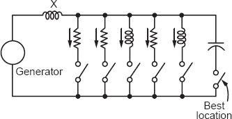
Figure 99.1
Q100. What is insulation resistance?
Ans. For an ideal dielectric, the insulation resistance will be infinite. For a lossy dielectric it will be in mega-ohms or of the order of 1012 Ω.
Insulation resistance is the resistance through which a small current flows through the volume and surface of an insulation. A parallel combination of volume resistance and surface resistance is called an insulation resistance.
Q101. Find the insulation resistance of the capacitor shown in Figure 101.1. The volume resistivity is Ps = 5 × 10¹² Ω = m and the surface resistivity, Ps = 1018 Ω.
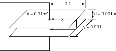
Figure 101.1
Ans. The volume resistance will be

The surface insulation resistance will be

Q102. Draw the electrical equivalent circuit of an ideal capacitor and lossy capacitor.
Ans. The electrical equivalent circuit of an ideal capacitor is shown in Figure 102.1 and that for a lossy capacitor in Figure 102.2.
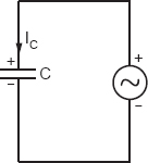
Figure 102.1

Figure 102.2
Q103. What is the name of the switch used for starting the motors?
Ans. Knife switch.
Q104. Why is the knife switch not made with one solid strip? Why do we use a spring attached supplementary strip?
Ans. To reduce the spark. If the knife switch is suddenly open or closed, a heavy spark will take place, with one strip case. The supplementary strip attached with a spring gives a time lag and the spark is reduced.
Q105. What is a hysteresis loss?
Ans. The hysteresis loss is the loss of power or energy in the form of heat when an iron specimen is given a cyclic current.
We supply a direct current to an iron specimen in the cyclic order shown in Figure 105.1.
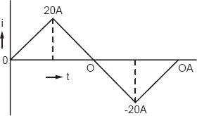
Figure 105.1
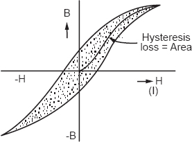
Figure 105.2
This power is absorbed in setting up the iron particles in a direction. The hysteresis loss can be found by a formula
Wh = Kh B 1.6 f
where Wh—hysteresis loss, Kh—constant, B—Flux density, f—frequency cycles per second.
Q106. What is eddy current loss?
Ans. The eddy current loss is the power or energy in the form of heat produced in a magnetic specimen. This I2R loss is in watts, if I is the eddy current and R, resistance to the eddy current offered by the iron path are noted.
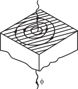
Figure 106.1
The eddy currents are due to the induced voltage which is caused by the pulsating flux.
RELAYS
Q107. What is the operating time of the instantaneous relay?
Ans. The time lapsed from the instant of energization to the instant of closing of contacts will be the operating time of the relay.
Q108. What is an order of the operating time of the instantaneous relay?
Ans. Of the order of 20 to 100 m-sec.
Q109. Why is it called instantaneous relay?
Ans. Due to a small operating time, it is called an instantaneous relay.
Q110. How does operating time depend on the energized current?
Ans. Practically independent of the value of current.
Q111. In which supply system is the instantaneous relay used?
Ans. It can be used for an A.C. supply system as well as for a D.C. supply system.
Q112. What is meant by snap action of attracted armature relay?
Ans. The process of armature getting attracted toward the magnet with a jerk is called snap action.
Q113. How can the current setting of the relay be changed without changing the number of turns on the coil?
Ans. (1) By changing the air gap lengths.
(2) By changing the tension in the spring.
Q114. Why is the reset value smaller than the pickup value?
Ans. Because at the time of resetting the length of air gap is smaller as compared to that while picking up.
Q115. For 50 c/s, A.C. supply, what will be the frequency of the vibration of the armature?
Ans. 100 c/s.
Q116. What is the practical utility of determining pickup and reset values?
Ans. This helps in determining the error between actual values and those written on the plug settings.
Q117. What is the reset value in D.C. relay?
Ans. Zero.
Q118. What arrangement is provided in the relay to save the C.T. from being open circuited when the plug setting is changed?
Ans. The upper electromagnet has a primary and secondary winding. The primary is connected to the secondary of C.T. in the line to be protected and is provided with tappings. These tappings are connected to plug setting bridge which is usually energized to give seven selections of tapping. The overcurrent range being 50 to 200% on steps of 25% of the element which tends to operate; therefore, when the pin is withdrawn to change the setting while the plug in service, the relay adopts a high setting, thus ensuring that the secondary is not open circuited while the relay operates.
Q119. Where do we use the directional overcurrent relays?
Ans. Overcurrent relays are the most widely used in the protection of electric machines, apparatus, transformers, and the transmission lines from overload.
Q120. What is setting current?
Ans. The minimum current at which the relay operates is known as the setting current.
Q121. What is a pickup value?
Ans. The pickup value is the setting current. It is expressed as a percentage of rated current of the line or apparatus protected.
Q122. What are the difficulties encountered in the differential protection of a transformer?
Ans. Different ratio C.T. are required at the primary and secondary, so as to balance the current and phase angle. This will cause difficulties in calculations. The C.T. ratio should be changed for different types of transformer connections. In tap changing, the C.T. ratio should be changed for every tapping. At the time of switching the magnetizing current of the transformer is very high, which will create unbalancing, and so the relay will operate. The C.T. and its ratio may be changed with different types of connections.
Q123. Why is the operating coil connected to the midpoint of the restraining coil?
Ans. Only then it will not operate by occurrence of any fault outside the protected zone. Because the current in the secondaries of both the transformers will be the same and no current will flow through the relay. This care must be taken under normal conditions.
Q124. In how many ways can the slope of the bias characteristic be changed?
Ans. The slope can be changed by changing the restraining factor Rf:

where Nr and No are the number of turns in the restraining coil and operating coil, respectively. It can be changed by changing Nr or No. The AT of the restraining coil can be changed, since the current (I1-I2) remains constant.
Q125. Why is it preferred to take on the X-axis of the time current characteristic of the relay multiples of the pickup value instead of the actual value of the current in amps?
Ans. The time current characteristics are the inverse definite minimum time type, since the time of operation is inversely proportional to the current and tends to definite minimum time as the current increases without limit, so that the multiple of the pickup value of current is taken along the X-axis. The multiple of the pickup value current is preferable to the actual value of the current. The actual value gives the quantity while the current setting multiplies the number of times of the relay current.
Q126. What are the conditions which must be satisfied before the overcurrent element is operated?
Ans. The directional overcurrent relay is set to operate for the condition when the current flowing in the given direction increases above the preset value. When the current in that direction increases over the given value, the direction at the element operates first and the circuit of the overcurrent element completes and hence the overcurrent element operates. This will complete tripping the circuit breaker, and the faulty element is cut off from circuit.
Q127. What is meant by directional control?
Ans. The directional element is fitted with the overcurrent relay for directional control. The directional control wants that the relay operate for the current flow in a given direction and not in the opposite direction. This type of arrangement is called directional control and is obtained by the directional element.
Q128. How would you reverse the directional features of the relay?
Ans. The torque generated in the relay will be: T = VI cos ϕ which is the power equation. The voltage, current, and power factor angle α will give us the torque. The reversal of the directional feature is that ϕ should exceed 90°. The torque will reverse.
T = K ϕ1 ϕ2 sin α = K VI sin (90 – α)
= K VI cos α.
Q129. What is a relation between iron loss and copper loss at the maximum efficiency of electrical machines?
Ans. Copper loss in watts equals the iron loss in watts at the maximum efficiency.
Q130. If we use a generator at overload, what will happen?
Ans. The losses will be more and the power generated will not be economical. Excessive overloading may cause the insulation failure.
Q131. Why do we use a commutator in D.C. machines with a brush gear?
Ans. In the conductor A.C. voltage is induced. We convert A.C. voltage to D.C. voltage by the commutator and brush gear.
Q132. If the brush gear is not fixed but rotated with the speed of the armature, what type of voltage will be obtained?
Ans. We will obtain the same voltage which exists inside the armature. No commutation will take place.
Q133. If the speed of the armature and that of the brush gear is not equal, which type of voltage will be obtained?
Ans. A.C. voltage of relative speed frequency will be obtained. The difference of the two speeds will appear as the frequency of the A.C. voltage.
Q134. Why do we use a soft iron cylinder in moving coil instruments of a permanent magnet type?
Ans. The moving coil is fitted in the iron cylinder. The fitting of the coil is for one purpose. The other purpose is for magnetic shielding for the moving coil.
Q135. What arrangement of damping is provided in the moving coil permanent instruments?
Ans. Damping is made by eddy currents induced in the aluminum form upon which the moving coil is wound.
Q136. Which type of instruments are used only for D.C. measurement?
Ans. Moving coil permanent magnet voltmeters and ammeters are made to measure D.C. voltage and D.C. current.
Q137. Which type of instrument is used for A.C. measurement only?
Ans. Induction type voltmeters, ammeters, and watt meters are made for A.C. measurement only.
Q138. Name the types of instrument which are used for both A.C. and D.C. types of measurement.
Ans. Moving iron type, electrodynamometer type, electrostatic type, and hot wire type instruments can measure both the A.C. and D.C. A common scale is provided for the measurements and marked A.C./D.C.
Q139. In order that the power loss in the instrument shall be small, the ammeter resistance must be small and the voltmeter resistance large. Justify this.
Ans. The power loss in the ammeter which measures a current will be given by
(P)A = I2RA watts
where RA is the resistance of ammeter coil. Obviously, the RA must small.
To measure the current I, the RA must be small to reduce the loss of energy.
The power loss in the voltmeter which measures a voltage, V will be given by

Obviously, to reduce the power loss (P)V, the voltmeter resistance RV must be large.
Q140. Name the type of error when a moving iron instrument is used for both A.C. and D.C. measurements.
Ans.(i) Hysteresis error
(ii) Stray magnetic fields.
(i)The readings are higher when descending values of current or voltage are measured than when ascending values are observed. This error may be reduced by making short iron parts.
(ii)Other magnetic fluxes can disturb the deflection of the needle. It can be reduced by magnetic screening by iron case or iron shield.
Q141. What is the law of resistance variation?
Ans. The law of increase of resistance of platinum with increase of temperature has been found to be:
| Rt = Ro[1 + αt + βt]2 | |
| where | Rt = resistance at temperature t° C. |
| Ro = resistance at temperature 0° C. |
alpha and β are the constants. Callender found that for pure platinum material α = 0.0037 and β = 0.00000057. A single constant α is used for the common applications and measurements
| Rt = Ro(1 + αt) |
This law is sufficiently accurate for small temperature changes.
Q142. In the broadest sense, instruments may be divided into how many classes?
Ans. Two classes:
(i)Absolute instruments; and
(ii)Secondary instruments.
The absolute instruments measure the quantity in terms of constants of instruments and the deflection. Tangent galvanometers and Rayleigh current balances are the examples. The secondary instruments measure the quantity in terms of the deflection of the instrument.
Q143. How many types of secondary instruments are used?
Ans. There are three types secondary instruments.
(i)Indicating
(ii)Integrating
(iii)Recording.
A common voltmeter, ammeter, and wattmeter are the indicating instruments.
Energy meter and ampere-hour meter are the integrating instruments, and path tracing of a quantity with time is made by the recording instruments.
Q144. A consumer had a claim that his meter reads much more than what he used to consume. The meter was repaired and it was found that the bill was 10% of the original bill, in spite of the constant consumption of the house owner. The company wanted to check the consumer’s activities and again the meter was checked and the bill was the same as the original bill. What had been done with the meter in between checking?
Ans. The connections of the current coil were changed. The 10% bill might be due to the voltage coil or creeping errors.
Q145. The pole of a D.C. machine is laminated and the yoke is not laminated, why?
Ans. The poles have the changing flux in the air gap, therefore, to reduce the eddy current losses the poles are laminated. The yoke has constant flux with no changes, therefore, eddy current loss is absent. We need not to make it laminated.
Q146. What is a stacking factor?
Ans. The ratio of iron content in the laminated varnished core is called the stacking factor. The factor is about 90% or 0.9. Due to stampings the net iron material is reduced to 90% and 10% will be varnish and air, etc.
Q147. What is impregnation? Why are insulating materials impregnated?
Ans. Impregnation is a process by which we fill the varnish or solidifying liquids into the pores of a material like clothes and papers. Solidifying liquids like the tung oil and linseed oils are useful for impregnation. Paraffin is the most useful impregnating liquid.
The cloths, papers, wood, and so on are impregnated to fill the pores of air. Air is a weak dielectric and it must be removed from the pin-hole. The mechanical and electrical properties of materials are improved through impregnation.
Q148. What is street main? What is consumer’s main? Which main has the higher current capacity?
Ans. Street main is the electric line installed on the street. This is one type of distributor. The consumer main is the connecting wire which connects the street main to the consumer house wiring.
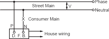
Figure 148.1
The street main has a higher capacity of current than the consumer main.
Q149. What is a feeder? What is a distributor? Which one link has higher current capacity?
Ans. A feeder is a line to feed the power from a generator to a substation transformer. It can be defined as a connecting link between a generator and the generator bus.
The distributor is a link which distributes power to the consumer. The street main may be a distributor from which the consumers take the power. Figure 149.1 will give a picture of feeders and a distributor.

Figure 149.1
Q150. What is an infinite bus bar? Why is an alternator connected to an infinite bus-bar?
Ans. The infinite bus-bar is a very large bus-bar where an infinite number of loads are connected in parallel. The average power factor, frequency, and voltage may be assumed constant. For a practical example, the connection of millions of lamps, fans, heaters, and other domestic appliances form a nature of infinite number of loads.
The control problem of an alternator becomes simple if we connect it to the infinite bus bar. The voltage and frequency of the alternator become constant, the red power and reactive power can be controlled by controlling the coal input and excitation, respectively.
Q151. Make a block diagram of an alternator to represent the inputs and outputs. How will you control the four outputs by two inputs available in an alternator?
Ans. The block diagram of an alternator is represented in Figure 151.1. There are four output variables and two input variables.
if: field current.
T: torque are the inputs.
P: real power in watts.
Q: reactive power in volt-amperes.
V: voltage and
f: frequency c/s are the output variables.
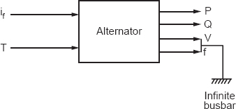
Figure 151.1
It is impossible to control four output variables with two input variables. Therefore, we must connect the voltage and frequency to the infinite bus bar where these may be kept constant.
Q152. Why do we call alternators synchronous machines?
Ans. The rotating magnetic field and the D.C. field of the rotor are in synchronism. Synchronism can be realized when the soldiers of a company make a left-right. The hands and legs are in synchronism, that is, moving without time lag.
Similarly, the field of the stator and the field of the rotor moves at one speed only. Therefore, we call it the synchronous machine. The synchronous speed is fixed by the poles and frequency:
If f = 50 and P = 8, then

The rotor of the alternator must be moved at 750 RPM only to keep the machine in synchronism.
Q153. Where will you use a synchronous motor?
Ans. We use synchronous motors in paper mills and cotton mills, which require a constant speed.
Q154. A direct current cannot pass through a capacitor but alternating current can pass, why?
Ans. The capacitor offers a high impedance to the current, therefore, the current will be zero. As a matter of fact the impedance is infinite:

Since ω = 0 for a D.C. supply.

If we give a supply of 50 c/s to the capacitor, the reactance will be finite and the current will flow. In the D.C. case the capacitor does not allow the current flow. The current will practically be zero, due to the open circuit.
Q155. If we supply a direct current to an A.C. network, what will happen?
Ans. The network will become a resistive network. The inductances will work as short-circuited and capacitances will be open circuited.
Q156. What is a reactance diagram? How does the reactance diagram become useful on a D.C. network analyzer?
Ans. In the case of A.C. networks, if the resistance of the systems is neglected, the reactance remains in the circuit. The circuit with the reactances only is called the reactance diagram. The reactance diagram is useful on the D.C. network analyzer to calculate the short-circuit current. We replace the reactance by the resistances on the analyzer.

Figure 156.1
(a) Impedance diagram
(b) Reactance diagram
(c) D.C. network analyzer diagram.
Q157. How will you recognize a Megger and a Megger Earth tester?
Ans. A Megger has only two points while the Megger Earth tester has three points. One point of the Earth tester is connected to the earth electrode.
Q158. Why do we measure the resistance of the earth electrode by Megger Earth tester but not with the simple Megger?
Ans. The resistance of the earth electrode or earth wire is not only meaningful, but we wish to measure the resistance of the earth vicinity, up to the length of 150 feet. The charge accumulated on the equipment must go to the earth immediately. The resistance will be a sum of R1 + R2 + R3 = RE. We call it the resistance of the earth connection.
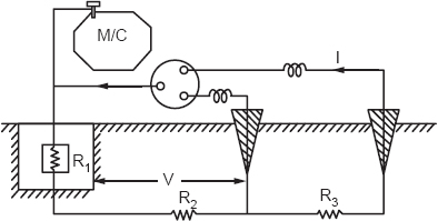
Figure 158.1
Q159. When there was no earth tester, how was earth resistance measured?
Ans. The earth resistance was measured by supplying 500 volts between the earth electrode and one peg of iron, 150 feet apart, by a generator. The current was measured by an ammeter flowing through the peg. A voltage was measured by a voltmeter between the earth electrode and a second peg at 75 feet away. The resistance calculated was
RE = V/I.
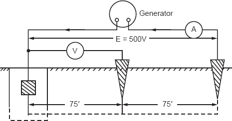
Figure 159.1
This was the primitive method to measure the earth resistance.
Q160. Why do we measure the earth resistance of an electric pole stay wire and stay peg in summer, winter, and rainy seasons?
Ans. To check the poles, whether the resistance is zero or nearly zero. If the resistance of the pole is not zero, install an earth wire and ground it by a coil. If the earth resistance of the pole is more than 1000 ohm, it must be reduced or dismantle it. The possibility of shock hazard is more if the insulator fails.
In all three seasons the earth resistance of the poles and stay wires must be recorded, for the safety of human beings and animals.
Q161. Why do we provide a plate in the bottom of an electric pole?
Ans. The plate is provided so that a proper contact of the earth may come with the pole body. The charge will go to the earth at a greater rate.
Q162. Why do we use a stay-wire with an electric pole?
Ans. This is used to support the pole against extra tension produced by a terminating line.
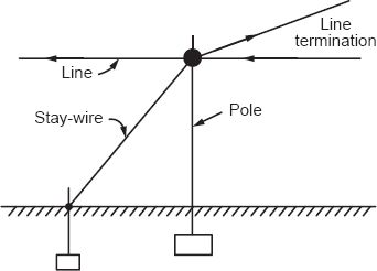
Figure 162.1
Q163. What is a thimble and where we do use it? Why do we use the thimble?
Ans. It is a M.S. oval type ring with a channel. The thimble is used for the binding of stay wire with the stay-peg through elbow. The thimble is used to save the life of the stay wire binding. By relative motion due to wind and animals, the stay wire gets friction. Its life will be reduced and may break at any time, paralyzing the electrical installation.
Q164. What is the length of a stay-peg?
Ans. About 6 feet in length for ordinary distribution.
Q165. How many types of line joints do you know?
Ans. Splicing: used for stranded line conductors.
Married joint: used for hard draw copper conductors
Scarf joint.
T-joint: used for terminating a line.
Q166. How many methods are used to make a house wiring?
Ans. Loop method and cut-method are the two methods generally used. In the cut method the wire is cut and in the loop method the wire is not cut into pieces, but a loop is used.
Q167. How many types of wiring do you know for installations?
Ans. Casing-capping wiring, batten wiring, cleat wiring, pipe wiring or conduit wiring, under wall wiring, etc.
Q168. Why do we provide a groove on the top of an insulator used in a telephone line or electric line?
Ans. The groove is provided to support the conductor and the binding of the conductor on the insulator is facilitated.
Q169. Why do we provide a petticoat to the insulators?
Ans. A petticoat is provided to safeguard the conducting pin short-circuited in the rainy seasons. The length of water flow stream is broken. The water will not reach the pin. The water is a good conductor and link of water stream conductor, and the link of water stream will make a short-circuit between the conductor and the pin or the pole and the earth.
Q170. Why do we keep the Carbon brushes in a magnetic neutral axis?
Ans. For a linear commutation and sparkless working of the machine is obtained. A maximum voltage is generated at this position. This also fixes the armature winding at 90° angle from the pole-axis or magnetic axis.
Q171. If we keep the brushes just under the poles or on the magnetic axis how much voltage will be generated in the armature winding?
Ans. Zero voltage will be induced in the winding as the linkage will be zero.
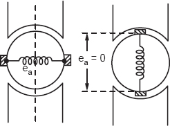
Figure 171.1
Q172. What is a commutation? What is a commutating coil?
Ans. Commutation is the process through which a current in a coil changes with time or brush length when the coil passes through the brush.
The coil which passes through the brush in a short period called the short-circuited coil or the commutating coil.
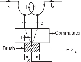
Figure 172.1
Figure 172.1 represents the short-circuited coil, C, which will be under the commutation for time period X for the brush length. The complete armature is throwing current to the brush at this state.
Q173. What is a dark commutation? Derive an equation for the dark commutating current in a simple manner.
Ans. Dark commutation is a sparkless commutation named a linear commutation. Current passes linearly in the coil under commutation and there is no chance of throwing sparks through the brushes.
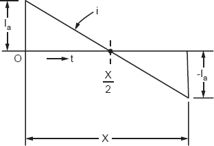
Figure 173.1
The derivation will be simple. We use Figure 173.1. The currents I1 and I2 will pass through the commutator segments producing uniform current density:
Or

Or

Q174. Which type of motor is used in the fans used in trains?
Ans. D.C. shunt motors.
Q175. The speed torque curves of a D.C. shunt motor and induction motor are similar–discuss. Where would these curves be suitable?
Ans. The speed falls slowly when a load is applied; this is called the shunt characteristic.
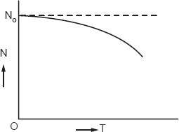
Figure 175.1
This is suitable for the centrifugal pumps, flour mills, and electric fans.
Q176. Define the magnetic flux line.
Ans. A line of magnetic flux originates from a north pole and reaches to the south pole and again to the north pole making a closed path. It is very necessary to make the closed path for the line for its existence.
Q177. Why do we use a yoke in the D.C. machine?
Ans. A yoke is used to make the path of flux complete. The flux-lines originate from the north pole and reach to the south pole through the air gap and the armature. From the south pole they reach to the north pole through the yoke.
Q178. Why do we choose diamagnetic materials as conductors?
Ans. Diamagnetic materials are such in which flux cannot enter. These repel the flux and eddy current losses are reduced.
Copper, silver, and aluminum are the diamagnetic materials. These have negative susceptibility, –Xm.
Q179. How can we find resistivity of mixtures?
Ans. The resistivity of mixtures is found by the logarithmic law of mixing. If the contents are specified by their resistivities, ρ1, ρ2 and ρ3 and volume constants V1, V2 and V3, we may find the total resistivity as follows.
V loge ρ = V1 loge ρ1 + V2 loge ρ2 + V3 loge ρ3 where V and P are the total volume and resistivity.
Q180. How will you find the permittivity of mixtures?
Ans. We may find the permittivity of mixtures by the logarithmic law of mixing. If ϵ1, ϵ2 and ϵ3 are the permittivity of the contents, and V1, V2 and V3 volumes, we have
V loge ϵ = V1 loge ϵ2 + V2 loge ϵ2 + V3 loge ϵ3.
Q181. How will you find the permeability of mixture magnetic materials?
Ans. By the logarithmic law of mixing as given above.
Q182. How will you determine the conductivity of mixtures?
Ans. The logarithmic law of mixing will be used as given above.
Q183. Which type of dielectric materials are used for the common purposes of power systems? Name some of them and mark their dielectric constant.
Ans. Paper, clothes, woods, asbestos, mica, rubber, ebonite bakelite porcelain, plastics, resins, etc., are common materials. The permittivity is between 1 and 4. The paper cloth, oils, woods, asbestos, etc., have permittivity of about 2.2.
Q184. Do you use the materials at a raw state? If you use the cloth as the insulator, will it work satisfactorily? If not, which process do you apply to the materials?
Ans. Materials are never used as dielectrics in the natural state but are impregnated by the solidifying liquids. Linseed and tung oils are commonly used vegetable oils for impregnation. Paraffin and wax are also used for the purpose.
Q185. Why do we use oil in a power transformer?
Ans. There are two main purposes for using oil in the power transformer.
(i)Cooling purpose, the heat is carried by the liquid in the contact to the winding up to the tank surface from where it is radiated.
(ii)Windings are insulated from the tank surface by the oil. The oil has a higher dielectric constant, 2.2, than air. It provides the higher capacitance.
Mineral oils are used as transformer oils, and cooling and insulating oils are called transformer oils.
Q186. What is a power oil? Do you consider transformer oil as a power oil?
Ans. Oils used in circuit breakers, switches, autotransformers, and other devices for cooling purposes and for quenching of the arc are called power oils. Transformer oil is also a type of power oil.
Q187. Why do we not use vegetable oils for the transformers?
Ans. Vegetable oils have higher viscosity and fast aging.
Q188. Why do we use a current transformer with wattmeter current coil in the short-circuit test on a transformer?
Ans. When a current coil rating is less than the current in the circuit, a current transformer of suitable ratio is used as shown in Figure 188.1.
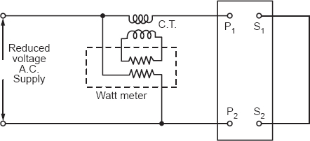
Figure 188.1
The coil of the wattmeter may be burned due to more current. It is for the safety of the instrument.
Q189. A wattmeter is used to measure the power using a current transformer. The multiplying factor of the wattmeter is 0.5 and the C.T. ratio is 20/5. Find the power taken by the circuit if the reading of the wattmeter is 120 watts.
Ans. If the multiplying factor is q and the C.T. ratio is a, then the power taken will be
W × q × a = Wa
120 × 0.5 × 4 = 240 watts.