Chapter 14
It’s the Brakes!
In This Chapter
 Understanding how a basic brake system is set up
 Knowing the difference between drum brakes and disc brakes
 Looking at the parking brake
 Exploring ABS and other electronic braking systems
This chapter deals with an automotive system that most people take for granted even though it may be the only system in your vehicle that can kill you if you don’t keep it in good repair. As you’ve probably guessed — especially if you read chapter titles — I’m talking about your brakes.
As with the other basic automotive systems covered in this book, I deal with brakes in two parts: This chapter covers the general theory behind brakes and braking systems, and Chapter 15 tackles the hands-on information you need to repair and maintain them.

Brake System Basics
One reason that today’s vehicles are the safest in history is that, since 1968, all vehicles come equipped with dual brake systems to ensure that if one set of brakes fails, the other set can still stop your car (see the “Dual brakes” sidebar later in this chapter). Your vehicle also has a dashboard light to warn you if your brakes are malfunctioning. A growing number of modern vehicles not only are equipped with hydraulic brake systems but also feature electronic brake systems that operate even more safely and efficiently.
Because electronic brake systems employ most of the same hydraulic parts as hydraulic systems, I start with the basics and get to the more advanced systems later in this chapter.
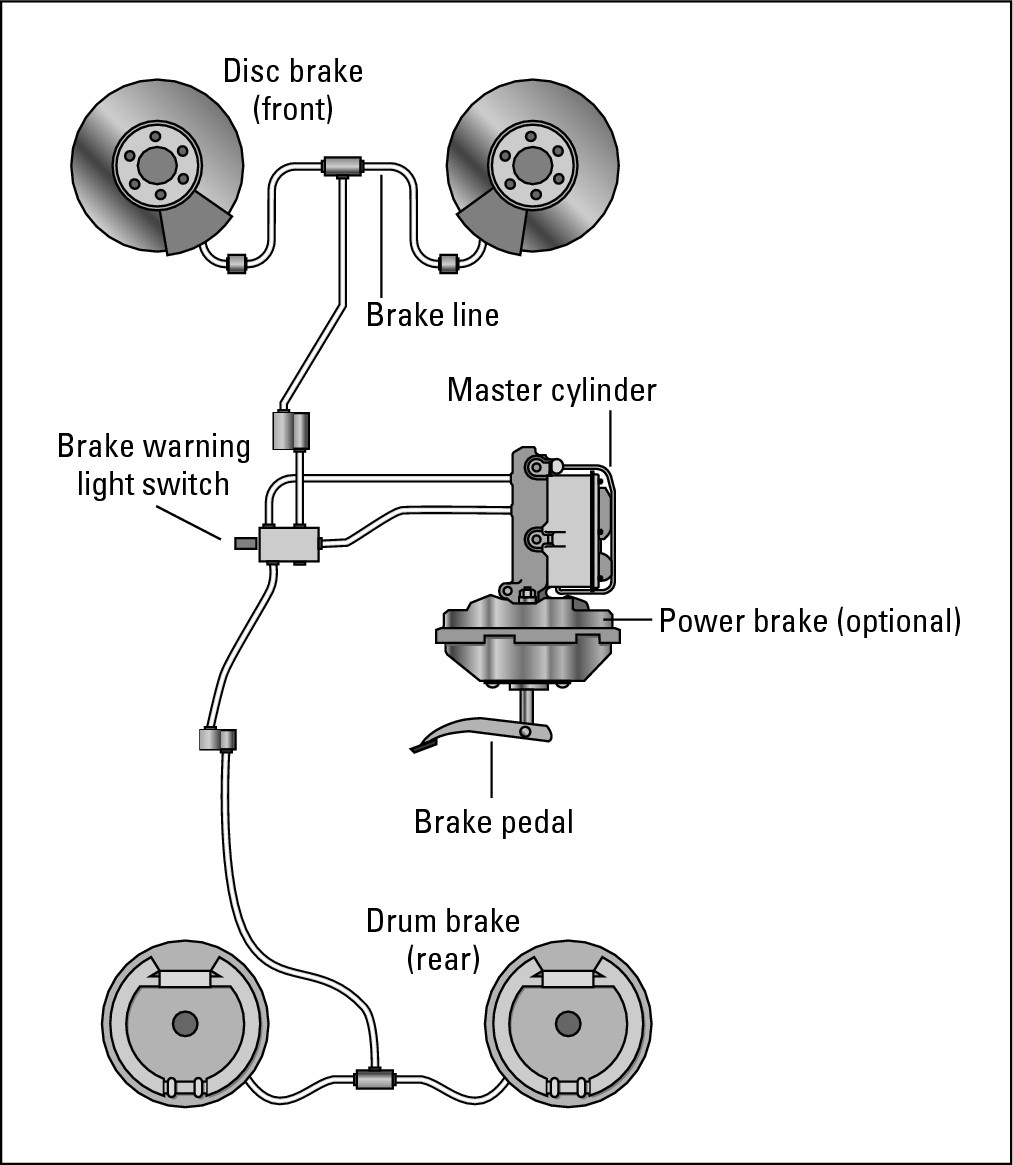
Figure 14-1 shows a basic brake system with a brake booster, disc brakes on the front wheels, and drum brakes on the rear wheels. Your vehicle may have disc brakes all around, but the principle is the same in any case.
|
Figure 14-1: A brake system with drum brakes at the rear and discs up front. |
|
The following sections take a look at each of the components of a basic hydraulic brake system, starting with the first point of contact between you and your brakes and working down the line to the brakes themselves.
The brake pedal
The brake pedal in your vehicle is attached to a shaft that leads to the brake master cylinder. When you step on the brake pedal, small pistons in the master cylinder force brake fluid out of the master cylinder and into the brake lines. (I tell you how to buy the proper brake fluid and work with it safely in the “Flushing and Changing Brake Fluid” section in Chapter 15.)

Power brakes
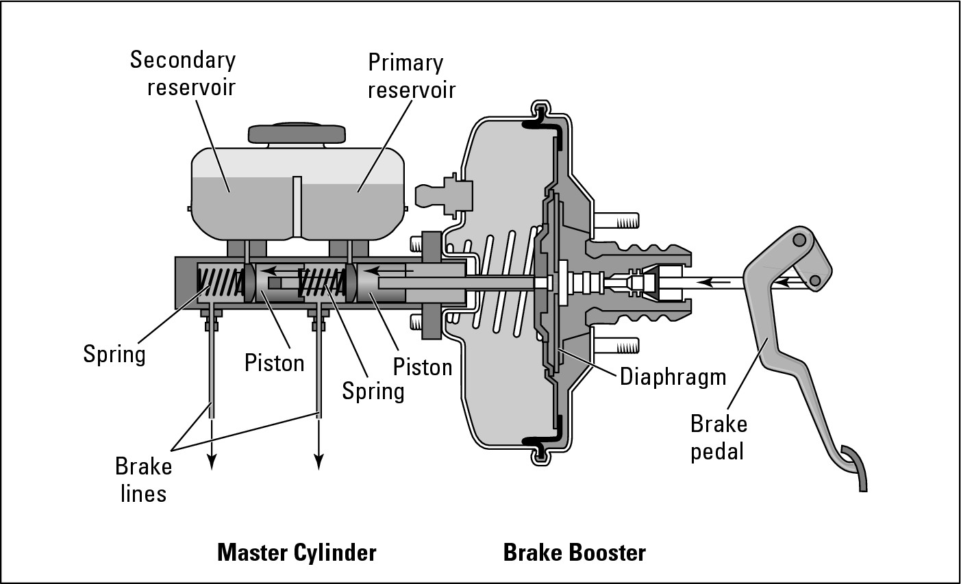
Today, most vehicles have power brakes with a brake booster located between the brake pedal and the master cylinder to increase the force applied to the pistons in the master cylinder so that your car can stop with less effort on your part (see Figure 14-2). The two most common types of power brake boosters are vacuum-assisted boosters, which use engine vacuum and atmospheric pressure to do the job; and hydraulic-assisted boosters (commonly referred to as hydro-boost units), which use hydraulic pressure from the car’s power steering to accomplish the same thing. Some vehicles with anti-lock braking systems (ABS) have a hydraulic pump to generate pressure for booster operation. (You can find a section on ABS later in this chapter.)
|
Figure 14-2: When you step on the brake pedal, the brake booster activates the master cylinder. |
|
Your owner’s manual can tell you what kind(s) of brakes you have on your vehicle, in case you don’t already know, but seeing for yourself is more fun. Later in this chapter, I cover each type of brakes in detail.
The brake master cylinder
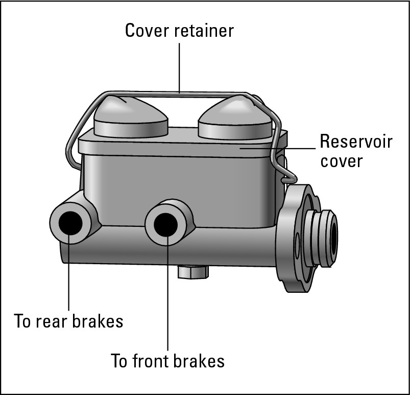
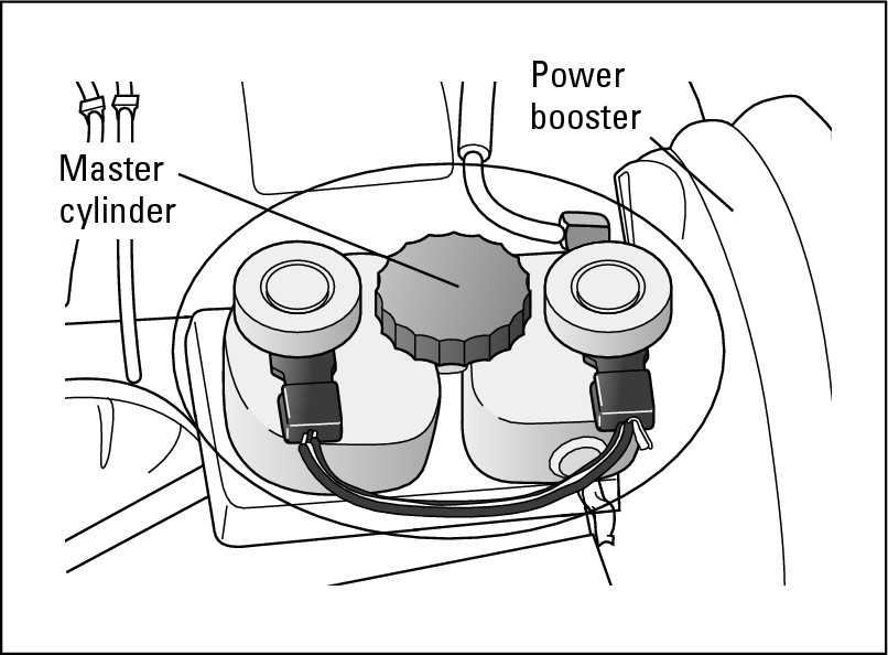
Under the hood of your car, usually up near the firewall on the driver’s side, you should see either a metal box (see Figure 14-3) or, on most newer vehicles, a plastic container (see Figure 14-4). This is the brake master cylinder (refer to Figure 14-2). It’s filled with brake fluid and is connected to your brake pedal, with brake lines leading from it to the four wheels of your vehicle. Stepping on the brake pedal activates the brake power booster, which activates the pistons in the master cylinder, forcing brake fluid out of the master cylinder into the brake lines. When you release the pedal, the fluid flows back into the master cylinder. In Chapter 15, I show you how to open and check the master cylinder safely. This task is also part of the monthly under-the-hood check in Chapter 2.
|
Figure 14-3: A metal master cylinder. |
|
|
Figure 14-4: A plastic master cylinder. |
|

Dual brakes
A dual brake system simply means that the inside of the master cylinder is divided into two compartments, each filled with brake fluid. On a vehicle with rear-wheel drive, one compartment has brake lines that lead to the brakes on the front wheels; the other compartment has lines leading to the brakes at the rear wheels (refer to Figure 14-3). If a leak or a block develops in one set of lines, the fluid in that com- partment is lost or useless. But the other compartment and set of brakes can still stop your vehicle. It may not stop smoothly, but it will stop, and in such a case, that’s all that counts! This simple modification has saved countless lives.
Most front-wheel drive vehicles have a diagonally split hydraulic brake system that ties the right-front wheel with the left-rear wheel and the left-front wheel with the right-rear wheel. That’s because the front brakes on front-wheel drive vehicles do almost 90 percent of the braking. By diagonally splitting the hydraulic system, you always have one front brake and one rear brake operating in the event of a hydraulic failure.
Brake lines
The brake lines run from the master cylinder along the frame of your vehicle to each wheel. The lines are made of steel except for the portions that lie right near your front wheels and your rear axle. These portions are made of rubber or synthetic material that’s flexible enough to contend with the greater amount of movement that takes place in these areas as the suspension system works and the wheels turn when you steer.
Brake fluid
Although electronic brakes using electric motors to do the work are in development, brake systems today still are activated by hydraulic fluid called, you guessed it, brake fluid. You can make your brake system work better and live longer if you change the fluid — or have it changed by your mechanic — once every 24 months, regardless of mileage. Brake fluid soaks up moisture from the atmosphere. As this water contaminates it, the boiling point of the brake fluid lowers until it can reach a point where it begins to boil as brake heat builds up. When that happens, the air bubbles in the boiling fluid cause the brakes to fail, a situation nobody wants. Chapter 15 tells you how to change brake fluid.
The parts discussed thus far are common to most hydraulic brake systems. Now for some of the major differences: When you press the brake pedal and force the brake fluid from the master cylinder into the brake lines, what happens next depends on the type of brakes you have. For many years, cars had drum brakes (see Figure 14-5) on all four wheels. As you can see in Figure 14-1, some vehicles have drum brakes on the rear wheels and disc brakes (see Figure 14-8) on the front wheels. Today, many vehicles have four-wheel disc brakes, and most have the power brakes described earlier in this chapter. Anti-lock braking systems (ABS) also have become popular, and I get to them shortly.
Drum Brakes
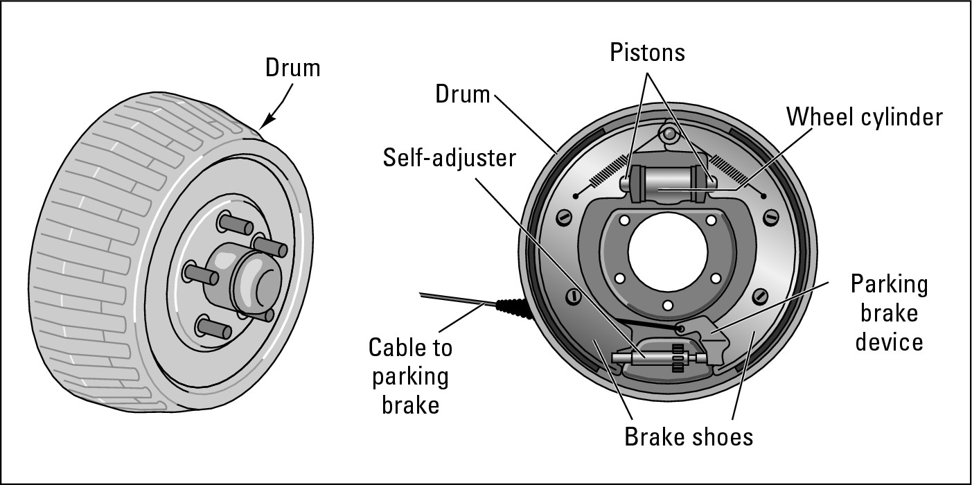
Drum brakes, shown in Figure 14-5, are the oldest type of brakes still on the road. Their main advantage is that they require less hydraulic pressure to stop your vehicle because the brake shoes tend to screw themselves into the brake drums after the pistons in the wheel cylinders push them there. The following sections get you acquainted with what’s inside drum brakes and how they work. Chapter 15 shows you how to access a drum brake and check its condition.

|
Figure 14-5: Anatomy of a drum brake. |
|
Brake drums
Brake drums are hollow steel cylinders located in back of each wheel (refer to Figure 14-5). Because the lug bolts that go through them are the same as the ones that go through the wheels of your vehicle, the drums turn when the wheels turn. If you keep your brakes in good condition and replace your brake linings before they become too worn, your brake drums should last for the life of your vehicle. If drums become worn, they can be “reground” or “turned” to a smooth surface — unless they’re worn more than their manufacturer’s recommendation (usually more than .060 of an inch), in which case the drums must be replaced. Chapter 15 shows you how to inspect your brake drums and get a fair deal if they need work.
Wheel cylinders
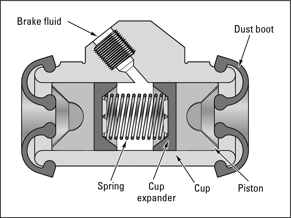
As you can see in Figure 14-6, wheel cylinders are small but powerful mechanisms located inside each brake drum on the brake backing plate.
|
Figure 14-6: Anatomy of a wheel cylinder. |
|
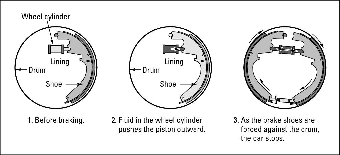
The brake fluid that’s forced through the brake lines by the piston in the master cylinder goes into the wheel cylinders. The fluid then activates the two small pistons located inside each wheel cylinder by forcing them farther apart. The pistons emerge from either end of the wheel cylinder and push against the brake shoes. Figure 14-7 shows how the wheel cylinders work.

|
Figure 14-7: A drum brake in action. |
|
Brake shoes
As you can see in Figure 14-7, brake shoes are curved pieces of metal that stop the vehicle when the pistons in the wheel cylinders push them against the inside of the brake drum. The brake shoes are attached to a set of springs that draw them back into place when you take your foot off the brake pedal. Chapter 15 provides tips on getting the best deal if your brake shoes have to be replaced.
Brake linings
Either bonded or riveted to the brake shoes are curved brake linings of tough, very heat-resistant material. As you can see in Figure 14-7, when the brake shoes are forced against the insides of the brake drum, the linings create friction, which causes the brake drum to stop turning. This in turn forces the wheels to stop turning, which stops the car.


Adjusting devices
Drum brakes that could be manually adjusted used to be popular, but today’s passenger vehicles have self-adjusting brakes. The self-adjusting device is located at the bottom of the brake backing plate. These devices are used to adjust the distance between the surface of the brake lining and the inside of the brake drum when you step on the brake pedal. As your brake linings become worn, the distance increases, and the adjustment compensates for that. If you didn’t have a self-adjusting device and your linings became very worn, eventually the brake shoes wouldn’t contact the inside of the drum and your car wouldn’t stop. You can see the self-adjusting device on the drum brake in Figure 14-5.
Disc Brakes
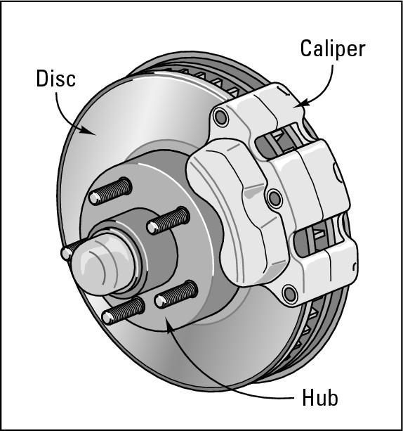
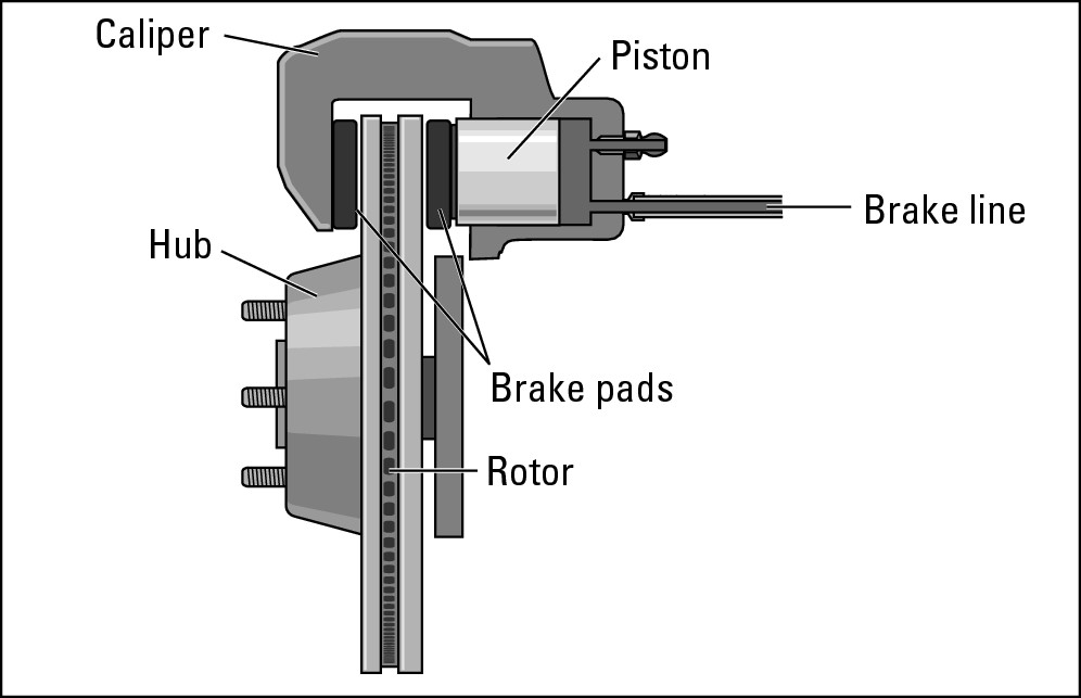
Disc brakes used to be found mainly on the front wheels of vehicles, with drum brakes at the rear (refer to Figure 14-1). Today most passenger vehicles have disc brakes all around. Each brake has a flat steel disc — you knew that, right? — sandwiched between a pair of calipers (see Figure 14-8) or a single caliper (see Figure 14-9). These calipers contain one or more pistons that force the brake fluid in the brake lines into the disc. Between the disc (sometimes called a rotor) and the pistons are brake pads, which operate in the same way that brake shoes do: They grab the disc with their friction linings and force the disc to stop turning, which in turn forces the wheel to stop turning and the vehicle to stop moving. The effect is the same as on a bicycle when the brakes grab the wheel directly to stop it from turning. Chapter 15 tells you how to inspect and troubleshoot disc brakes.
|
Figure 14-8: A multiple caliper disc brake. |
|
Older vehicles use fixed-caliper brake systems in which one or two pistons on each side of the disc push the pad against it. A single-piston floating-caliper disc brake system is becoming increasingly popular (see Figure 14-9). When you apply the brakes, the caliper moves from side to side and centers itself. Because these systems are self-adjusting, more reliable, and less expensive, they’ll probably become the standard.
|
Figure 14-9: Anatomy of a single-piston, floating-caliper disc brake. |
|

The Parking Brake
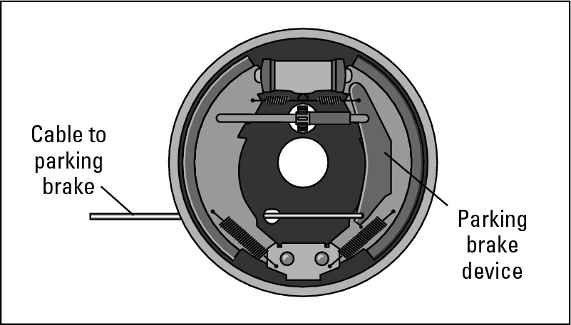
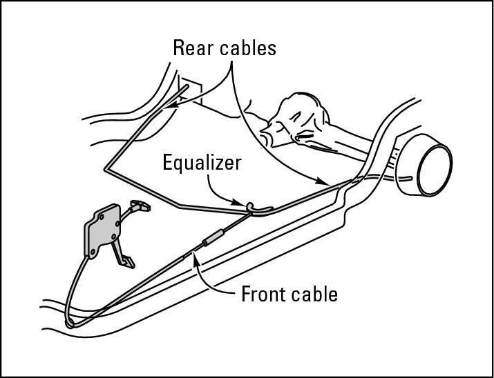
The parking brake, or emergency brake, is usually attached to a car’s rear wheels. On vehicles with rear drum brakes, the parking brake is usually attached with cables to the rear brakes, as shown in Figure 14-10. These are called integral parking brakes (see Figure 14-11). Although most newer vehicles have self-adjusting systems, if your vehicle doesn’t you can easily adjust the cables, which run underneath the car, by turning a screw that controls the tension on the cable. Chapter 15 provides instructions on how to do so.
|
Figure 14-10: A cable activates the parking brake system on a rear-wheel drum brake. |
|
|
Figure 14-11: An integral parking brake system. |
|
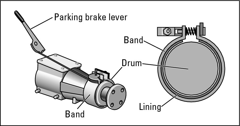
On other vehicles with drum brakes, different devices do the same job. Some parking brakes on vehicles with rear-wheel drive are linked to the transmission, and rather than activating the rear brakes, they stop the driveshaft from turning the rear wheels. On these brakes, shown in Figure 14-12, the band and lining are attached to a drum on the transmission. When you pull the lever, the band squeezes the lining against the drum, and the driveshaft stops turning. When a transmission-type parking brake doesn’t seem to be performing properly, have a professional check it.
|
Figure 14-12: A transmission-type parking brake system. |
|
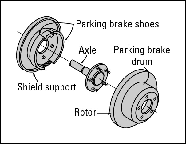
If you have rear disc brakes on your car, it may incorporate a parking brake that works like a mini-drum brake attached to the rear wheels (see Figure 14-13). Most parking brake systems for vehicles with rear disc brakes, however, employ the disc brake itself. Vehicles with disc brakes on both front and rear wheels use a cable to activate their parking brakes. You can see how it all hooks up in Figure 14-14.
|
Figure 14-13: A parking brake system on a rear-wheel disc brake. |
|
|
Figure 14-14: A cable activates the parking brake system on some rear-wheel disc brakes. |

|
Anti-Lock Braking Systems (ABS)
Anti-lock braking systems (ABS) are designed to prevent skidding and enable you to keep steering control of your vehicle until you can stop safely. This system also often shortens the distance your vehicle takes to stop and can prevent the tire damage that would result if you had to stop with the wheels locked.
ABS comes in two types: two-wheel and four-wheel. Some light trucks and vans have a two-wheel anti-lock braking system on the rear wheels that maintains directional stability. Although the front wheels can still lock up, the vehicle continues to move in a straight line. With just enough pressure applied to the brake pedal, the driver can control the steering. You find four-wheel anti-lock braking systems on other light trucks and most cars. These prevent all four wheels from locking up, which enables you to maintain steering ability in emergency stopping situations. If no impending lockup occurs, the ABS stays in standby mode.
How ABS works


If the anti-lock system has a problem, a warning light on the dashboard comes on and normal braking without anti-lock takes over. So if your amber anti-lock light illuminates, remember that you still have normal brakes. Just pump them and steer in the proper direction as though you’d never heard of ABS. And be sure to get the ABS fixed as soon as possible!
What ABS doesn’t do
.jpg)

Other Electronic Braking Systems
Because the brake system is such a vital feature of every vehicle, the technology for creating safer and more responsive systems is constantly developing. Newer electronic braking systems now exist that provide additional advantages, often coupled with ABS. The following sections cover two that are in production now.
Brake Assist (BA)
Brake Assist (BA) is like having a superhero in the car to save you in an emergency. It keeps an electronic eye on how you’re braking, and if you suddenly get into an emergency and have to stop short, BA automatically boosts the power of the brakes to help you. When you’re out of trouble and take your foot off the brake, the system automatically does so too and resumes its surveillance.
Originally offered as an option on high-end vehicles, often as part of a “pre-collision” package, BA is becoming available on more vehicles as the cost of the system goes down. You often find it combined with EBD, which I cover next.
Electronic brakeforce distribution (EBD)
First popular on luxury vehicles and some SUVs, electronic brakeforce distribution (EBD) ensures that braking power is distributed proportionately among all the wheels. If a vehicle carries a heavy or unequally distributed load, ordinary brake function can be skewed to one area of the vehicle, causing it to pull to one side or even sending it into a skid. To ensure stability, EBD automatically distributes the force of the brakes proportionately to all the wheels so that the vehicle can stop safely.
