Chapter 5
The Electrical System: Your Car’s Spark of Life
In This Chapter
 Keeping systems in synch with the engine control unit (ECU)
 Checking out the major electrical subsystems: Starting, charging, and ignition
 Paying attention to indicator lights on the dashboard
 Getting enlightened with fuses, directional signals, and headlights
The electrical system includes several subsystems that provide your vehicle with that vital spark that makes it start and then keeps it running. It’s one of the many systems on a vehicle that’s monitored and controlled by a kind of “super computer” called the engine control unit, or ECU for short. You encounter this god-like critter in several chapters of this book, so you should meet it before you get to the various systems that form the electrical system.

Introducing the Engine Control Unit (ECU)
The engine control unit (ECU) is the most powerful computer on a vehicle. It uses a variety of sensors to monitor and control most of the engine functions of the car, including the electrical, fuel, and emissions control systems. Among other tasks, the ECU fires the fuel injectors on fuel-injected engines, fires the spark plugs, and controls valve timing, emissions controls, the fuel/air mixture, and even the cooling fan. The ECU itself rarely malfunctions, is the key to the diagnostics that pinpoint problems, and is primarily responsible for managing the fuel efficiency and performance of your vehicle.
Moving on to the electrical system (see Figure 5-1), here are some of the services that the individual systems and major parts involved in the electrical system perform:
 The
starting system,
unsurprisingly, provides the initial power to get your engine started.
 The
ignition system
fires the
spark plugs
so they can cause the fuel and air to “combust” and drive your engine.
 The
charging system
generates electrical power for the various systems in your vehicle that depend on electric current, and it regulates the power flowing to the battery to keep it from running down.
 The
battery
stores excess current for future needs.
 Various
circuits
run a mixed bag of electrical gadgets, like your vehicle’s horn, headlights, and so on, most of which are protected by
fuses.
|
Figure 5-1: The electrical system. |

|
The following sections explore each of the basic subsystems that make up the electrical system.
The Starting System
The starting system, shown in Figure 5-2, is the portion of the electrical system that gets your vehicle started. When you turn your key in the ignition switch to “Start” (or activate the ignition by pushing a button), the action closes a circuit that lets electrical current flow from your car’s battery to its starter. On the way, the current passes through a device called the starter solenoid. Basically, all the solenoid does is pass the current along and move the starter gears into contact with the flywheel. You don’t adjust or replace it unless it breaks down.
|
Figure 5-2: The starting system. |

|

As you try to trace the wiring through the starting system, if you find a couple of parts that I haven’t mentioned yet, just hang in there. Like the solenoid , you don’t have to fuss with these parts unless they fail; and if they fail, they have to be replaced by a professional.
The following sections give you a closer look at each part of the starting system. Be sure to read them before undertaking any of the electrical work covered in Chapter 6.
The battery
The battery is the big box that sits under the hood, usually up near the front of the vehicle. It’s filled with acid, distilled water, and a set of plates that are combined into “cells” (see Figure 5-3) that produce electric current for starting the car, turning on the lights, and powering the ignition system. The battery also stabilizes the voltage in the electrical system and provides current whenever the electrical demands exceed the output of the charging system. Quite a helpful gadget!
|
Figure 5-3: Cutaway view of a battery. |

|


Most vehicles are negative ground, which means that the wire from the negative terminal is attached to the frame of the vehicle to ground it; the wire from the positive terminal leads to the starter, ignition, and so on.
Today, most batteries are sealed and don’t require much maintenance. However, deposits do form on the terminals, and they can impede the flow of current. Chapter 6 tells you how to check your battery and remove these deposits.

I know what the problem is; I just don’t know where it is . . .
After I took my first class on the electrical system, I went out one morning and found that my car, Tweety Bird, wouldn’t start. I remembered my instructor saying that if you hear a clicking noise (that’s your solenoid) but your engine won’t start running, you probably have a loose wire somewhere between the ignition switch and the starter. So I opened the hood (it was only the second time I’d gotten that far) and peeked in. Sure enough, I saw a cluster of wires on the firewall in front of my steering wheel. I could see where the wires ran along the frame of the car to the battery, but after that I got lost. I ended up calling the AAA.
When the AAA truck arrived, I proudly informed the technician that I knew what was wrong. “It’s just a loose wire between my battery and my starter,” I announced. “Then why didn’t you fix it yourself?” he asked. “Because I don’t know which gadget is the starter!” He was nice enough to keep from laughing, and I felt better when the problem did turn out to be a loose wire on the starter. He also pointed out the starter and showed me the wires that connected to it.
The starter
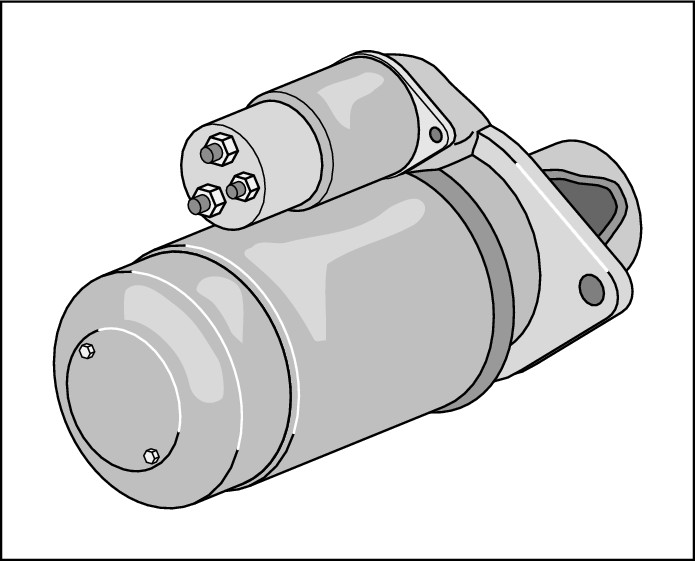
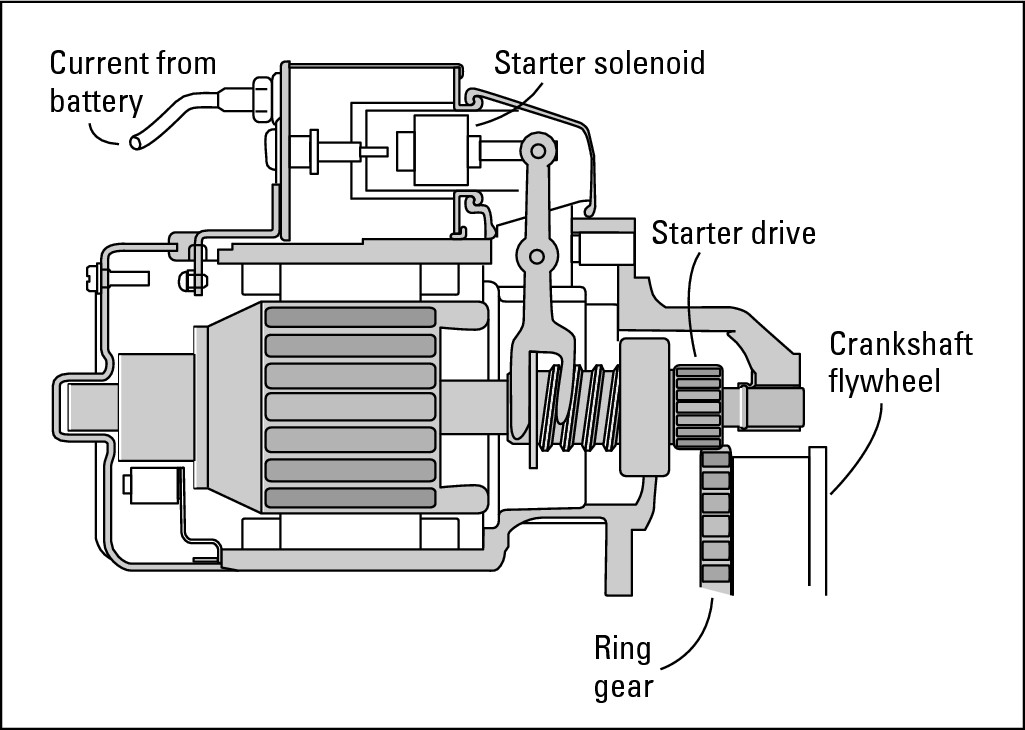
After the battery sends the current to the starter solenoid (refer to Figure 5-2), the current goes to the starter. The starter is the device that makes your engine turn over. (Figure 5-4 shows what a starter looks like, and Figure 5-5 shows how a starter works.) It’s an electrical motor with a gear called a starter drive at one end. The starter drive engages a ring gear on a flywheel that’s bolted to the back of the engine crankshaft. When you turn your key in the ignition switch (or push the ignition button on some vehicles), the starter drive slides down the shaft and engages the ring gear. This spins the flywheel, which starts the crankshaft turning so that the pistons can go up and down, the spark plugs can fire, and the engine can start running. As soon as the engine is started, the starter has done its job.
|
Figure 5-4: A starter with a starter solenoid attached. |
|

|
Figure 5-5: Anatomy of a starter. |
|
.jpg)
The Charging System
After you start your engine, it (usually) runs at a nice steady rumble unless you have a hybrid or electric vehicle (EV). EVs run silently, and hybrids are silent when operating on the electric motor only (see Chapter 10). The rumble in a conventional vehicle is possible because as soon as the pistons in the cylinders start to go up and down, your engine begins to run on its usual diet of fuel and air (read all about it in Chapter 7). When you let go of the key and your ignition switch moves from “Start” to “On,” the electric current stops flowing to the starter but continues to flow through the charging system (see Figure 5-6) and the rest of the electrical system.
The alternator
The running engine drives a belt that enables your alternator to produce electric current for the rest of the trip. Here’s how it does this: Your alternator (see Figures 5-6 and 5-7) replaces the electricity that was taken from the battery when you started the car. Then, every time your battery sends out some of its “juice,” the alternator replaces it.
|
Figure 5-6: The charging system. |

|
|
Figure 5-7: The alternator. |

|

When the alternator is generating electric current, it’s said to be charging. Although most cars just have dashboard “idiot lights” that go on if the alternator isn’t functioning properly, some vehicles have gauges called voltmeters that show whether the system is charging or discharging. They either have a “C” at one end and a “D” at the other end of the scale or a range of voltage levels (usually from 8 to 18).

The alternator also supplies your electrical system with current to run the radio, headlights, and so on. I get to that equipment at the end of this chapter.
The voltage regulator
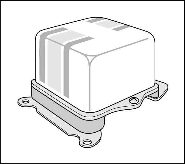
The voltage regulator (see Figures 5-6 and 5-8) is a device that controls the alternator. On older cars, it’s a little box mounted somewhere under the hood. On newer cars, it may be mounted inside the alternator or inside the ECU. If the voltage regulator fails, the alternator is literally “powerless.”
|
Figure 5-8: One type of voltage regulator. |
|
The Ignition System
The purpose of the ignition system is to ignite, or fire, the spark plugs in order to generate power to run the engine. To do so, the battery sends current to the ignition coil. Then that high voltage goes on to the spark plugs — either through a distributor, if you have an older vehicle, or directly to the spark plugs, if you have a newer one.

As later sections explain, both types of electronic ignition systems employ electronic parts. Unlike older systems, except for the spark plugs, their components don’t need to be replaced unless they break down. The good news is that they tend to be relatively trouble-free. The bad news is that if they do break down, you have to pay a professional to replace them.
Because all types of ignition systems employ spark plugs, you get to explore them first. Read on!
The spark plugs
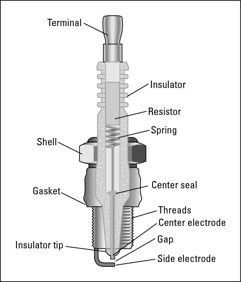
Spark plugs are located in the cylinders of your vehicle (look ahead to Figure 5-17). They deliver the spark of voltage to the combustion chamber just when the fuel/air mixture is at the point of greatest compression. The resulting combustion provides the power to propel your vehicle. Chapter 6 tells you how to “read” your spark plugs for clues as to how your vehicle is running and provides instructions for removing, gapping, and replacing spark plugs. Figure 5-9 shows you the various parts of a spark plug. You need to get to know them if you want to work on them yourself.
|
Figure 5-9: Anatomy of a spark plug. |
|
The location of the cylinders varies from one type of engine to another; the order in which the spark plugs fire the fuel in the cylinders differs from one engine to another as well. The next two sections tell you about cylinder sequence and firing order. It’s good to know how this works because if the spark plugs aren’t firing properly, your engine is as “out-of-tune” as an orchestra whose players aren’t keeping time. (That’s probably why they call it a tune-up.)
Cylinder sequence
The cylinder sequence of an engine is the order in which the cylinders of the engine are numbered. This sequence varies from one type of vehicle to another, depending on whether it has front-wheel drive or rear-wheel drive and whether it has an in-line engine, with the cylinders lined up in one row, or a V-type engine, with the cylinders in two parallel rows.
Here are cylinder sequences for several types of engines:
 Vehicles with
front-wheel drive
have
transverse engines.
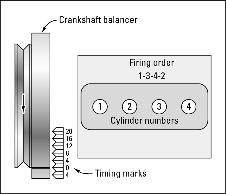
On both in-line and V-type engines, the cylinders run from one side of the vehicle toward the other. Aside from being set cross-wise, they have the same sequence and firing order as their
rear-wheel drive
in-line or V-type counterparts (see Figure 5-10).
|
Figure 5-10: The cylinder sequence and firing order of an in-line 4-cylinder transverse engine. |
|
 In all U.S.-made in-line 4- and 6-cylinder vehicles with rear-wheel drive, the cylinder nearest the front is called the #1 cylinder. The numbering for the rest of the cylinders (#2, #3, #4, and so on) runs in sequence back toward the
firewall
at the rear of the engine compartment (see Figure 5-11).
|
Figure 5-11: The cylinder sequence and firing order of an in-line U.S. 6-cylinder engine with rear-wheel drive. |

|

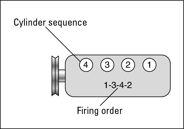
Some foreign automakers reverse the cylinder sequence. As you can see in Figure 5-12, the #1 cylinder is at the rear, near the firewall. If you have a foreign car and no owner’s manual, ask your local dealer where your #1 cylinder is.
|
Figure 5-12: The cylinder sequence and firing order of a foreign in-line 4-cylinder engine. |
|
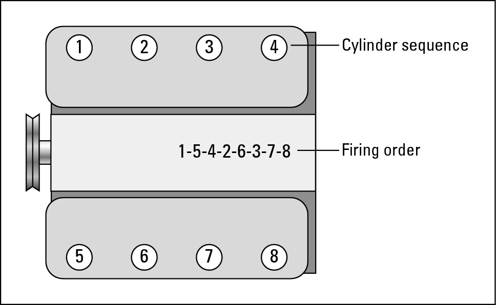
 V-8 engines aren’t as easy to figure out. Most Ford V-8s with rear-wheel drive have the #1 cylinder in the front on the passenger side of the car. Then cylinders #2, #3, and #4 follow it toward the rear firewall. The #5 cylinder is up front on the driver’s side, with cylinders #6, #7, and #8 in sequence going toward the rear (see Figure 5-13).
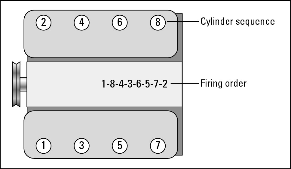
 On most other vehicles with V-8 engines and rear-wheel drive, the #1 cylinder is up front on the driver’s side, with cylinder #3, #5, and #7 proceeding toward the rear of the vehicle. Then cylinder #2 is up front on the passenger side, with cylinders #4, #6, and #8 following (see Figure 5-14).
|
Figure 5-13: The cylinder sequence and firing order of most Ford V-8 engines. |
|
|
Figure 5-14: The cylinder sequence and firing order of many other V-8 engines. |
|

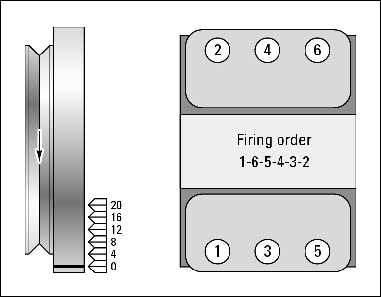
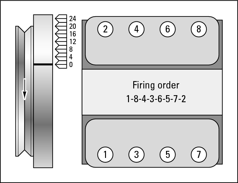
Firing order
.jpg)
The cylinders fire in very swift sequence, and the result is a fairly stable engine. The firing order is printed inside each of the engines shown in Figures 5-10 through 5-16. Trace the path of combustion back and forth through each of these engines to see how the shock of combustion is distributed to avoid rocking the engine. And remember, the whole thing happens very rapidly.
|
Figure 5-15: The cylinder sequence and firing order of a transverse V-6 engine. |
|
|
Figure 5-16: The cylinder sequence and firing order of a transverse V-8 engine. |
|
Now that I’ve dealt with the basics, the following sections deal with the two types of electronic ignition systems: the modern ones that no longer have distributors, and the older electronic ignitions with distributors.
Modern distributorless ignition systems
Found in most vehicles from the mid-1990s on, distributorless ignition systems (see Figure 5-17) have fewer moving parts and are much more fuel- efficient and less prone to breaking down than those with distributors. In all distributorless ignition systems, the ECU or a dedicated ignition control module (ICM) controls when the spark plugs fire and ignite the fuel/air mixture in the cylinders, which provide the power that propels the vehicle.
The following sections take a closer look at the electronic components found in modern distributorless electronic ignition systems (refer to Figure 5-17).
|
Figure 5-17: A distributorless ignition system. |

|
The electronic coil module
The electronic coil module does the same thing in a much more sophisticated way as the ignition coils and distributor on older vehicles did: It transforms the relatively small amount of electrical voltage (12 to 14 volts) that it receives from the battery into a big enough jolt of voltage (15,000 to 60,000 volts) to jump the spark plug gap. On most vehicles, a set of spark plug wires (sometimes called ignition cables) carries the high voltage to each spark plug.

Ignition system sensors
An electronic ignition system relies on a number of electronic sensing devices that feed information to the ECU, or a dedicated ignition control module (ICM) (see Figure 5-17), which sends the signals that fire the spark plugs at the proper time.
A crankshaft position sensor (refer to Figure 5-17) is mounted on the engine block and can read the position of, you guessed it, the crankshaft. It’s one of the sensors that tells the ICM when to fire each spark plug by keeping track of where the crankshaft is and how fast it’s spinning at any given time.
A camshaft position sensor found on distributorless ignition systems (refer to Figure 5-17) is another trigger device. It helps the spark plugs to fire at the right time, provides the data to synchronize the fuel injectors, and identifies misfiring cylinders.
Electronic ignitions with a distributor
Although most more recent vehicles don’t have distributors, many built from the mid-1970s to the mid-1990s still have them. (If your vehicle doesn’t have one, you can disregard this section and bop on down to the sections “Warning Lights and Malfunction Indicator Lights (MIL)” and “Other Electrical Gadgets.”) In an ignition system with a distributor, the distributor works in much the same way as the old-fashioned mechanical distributor that preceded it, but without all the moving parts that constantly needed adjusting. It still gets voltage from a coil and distributes it to each spark plug in turn. The good news is that electronic distributors are relatively trouble-free. The bad news is that if they break down, you have to pay a professional to replace them. They include the following parts, which can be seen in Figure 5-18:
|
Figure 5-18: An electronic ignition system with a distributor. |

|
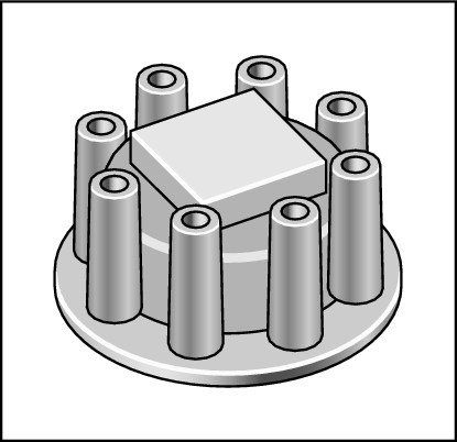
 The
distributor cap
(shown in Figure 5-19) sits atop the distributor to protect the parts inside from the elements. Current enters and leaves the distributor via the coil and spark plug wires that run through holes in the cap to each spark plug.
|
Figure 5-19: A distributor cap for an electronic distributor. |
|
 The
rotor
(refer to Figure 5-18) sits atop the distributor shaft inside the distributor. As the distributor shaft turns, the rotor rotates with it and points toward the terminal at the base of each spark plug wire so that each plug can fire in the correct order. For example, when the rotor’s pointing at the terminal of the wire leading to the #1 spark plug, it directs the current to that spark plug at precisely the time when the
fuel/air mixture
in the #1 cylinder is waiting to be burned.
 The
armature
(refer to Figure 5-18) sits inside the distributor, revolving past a
sensor
called the pickup coil. Each time one of the teeth on the armature passes the sensor, it creates voltage that signals an
ignition control module (ICM)
to shut down the primary circuit in the coil. This “fires” a jolt of high voltage to the secondary coil circuit, which shoots it out through the rotor to the proper spark plug. A circuit in the electronic module switches the primary circuit back on between each “firing.”
 The
ignition control module
is a transistorized component that triggers the ignition coil to fire high voltage. The module is a “non-wear” component that replaced the old-style “breaker” points in the early to mid-1970s.
 A
pick-up coil
is a magnetic pulse generator that tells the ignition control module when to fire the spark plugs. Some vehicles use a Hall-effect switch or a photoelectric sensor to do the same thing. It probably doesn’t make much difference which type your vehicle has because there’s no need for you to develop a personal relationship with it.
Warning Lights and Malfunction Indicator Lights (MIL)
Until fairly recently, vehicles were equipped with either dashboard gauges that monitored your vehicle’s temperature, oil pressure, charging system, and fuel level; or warning lights that told you something bad had already occurred in one of these areas (which is why we usually called them “idiot lights”).
The warning systems on today’s vehicles are much more efficient. Warning lights still tell you how much fuel you have; whether the hood, trunk, or a door is open; or if the parking brake is engaged. They beep at you like a frustrated parent if you don’t put your seat belt on. And malfunction indicator lights (MIL) check almost every system and warn you about problems that may need to be corrected.
The only trouble is that MILs can be so enigmatic about what’s gone wrong — especially when the ominous words “Check Engine” appear — that they can be very unsettling. That warning can apply to the engine, emissions, or accessories, so at first you can’t know if it’s just that your gas cap is loose or if major surgery is required.
When I turn on Esmerelda’s engine, a whole panel of little yellow symbols lights up. Many of these MIL are undecipherable. Others are initials that stand for . . . what? My owner’s manual describes most of them, but because these lights only stay on for seconds, it’s hard to keep track of them. And if one of them stays lit (bad news!), basically all the owner’s manual advises is to head for the dealership. Because that means I have to pay someone to put the car on a scan tool and “read the codes,” as a confirmed do-it-myselfer, I’m not happy.
However, because the MIL report the findings of the electronic sensors that constantly monitor your vehicle’s airbags, traction control, ABS system, ECU, transmission, and other vital systems — all of which you can’t work on yourself — if one of them stays lit after the others go out, it’s probably a good idea to head for the car doctor. Failing to do so can void your warranty or really damage your vehicle.

Other Electrical Gadgets
In addition to what I cover in the alternator section earlier in this chapter, by keeping the battery charged, the alternator also indirectly supplies the electrical current for the sound system, headlights, taillights, directional signals, defroster/heater/air conditioner blower, and other electrical gadgets. Although most of these components require professional repair, the following parts are pretty easy to deal with yourself:
 Fuses protect electrical component circuits the same way they do in a home. The fuses are located in a fuse box that’s usually found under or near the dashboard and possibly under the hood. Your owner’s manual should show you where the fuse boxes on your vehicle are, or you can crawl under the dashboard and trace the wires from your sound system until you reach the fuse box. See Chapter 6 for instructions on checking fuses and replacing a burned-out fuse.
 Windshield wipers need to be checked and their blades replaced periodically. Chapter 2 provides tips on checking and replacing your windshield wiper blades and windshield washer fluid.
 Directional signal flashers on your dashboard do more than tell you whether the directional signals themselves are flashing. They’re also designed to provide clues to malfunctions elsewhere on your vehicle! Chapter 21 tells you how to decipher these clues and rectify the problems that they indicate. For information about replacing directional signals, flip to Chapter 6.
 Headlights and headlamps have been considerably improved in recent years. Although vehicles with
sealed-beam units
and old-style light bulbs are still on the road, more modern vehicles have headlamps filled with halogen or Xenon gas. The Xenon headlamps are also known as
HID (high intensity discharge) lamps.
They’re brighter and use less power than halogens do. Most of these are no more difficult to adjust and replace than sealed- beam units were (see Chapter 6 for instructions on how to replace headlights and headlamps).

Headlight development continues. Innovations that already exist and will become more widely available include adaptive front lighting systems (AFS) that can swivel to illuminate a corner and lightweight LED headlamps that have the potential to outlive your vehicle.