Chapter 7
The Traditional Fuel System: The Heart and Lungs of Your Car
In This Chapter
 Getting familiar with basic fuel system parts
 Understanding fuel injection
 Exploring the four-stroke power cycle
 Appreciating supercharging and turbocharging
 Investigating the exhaust system
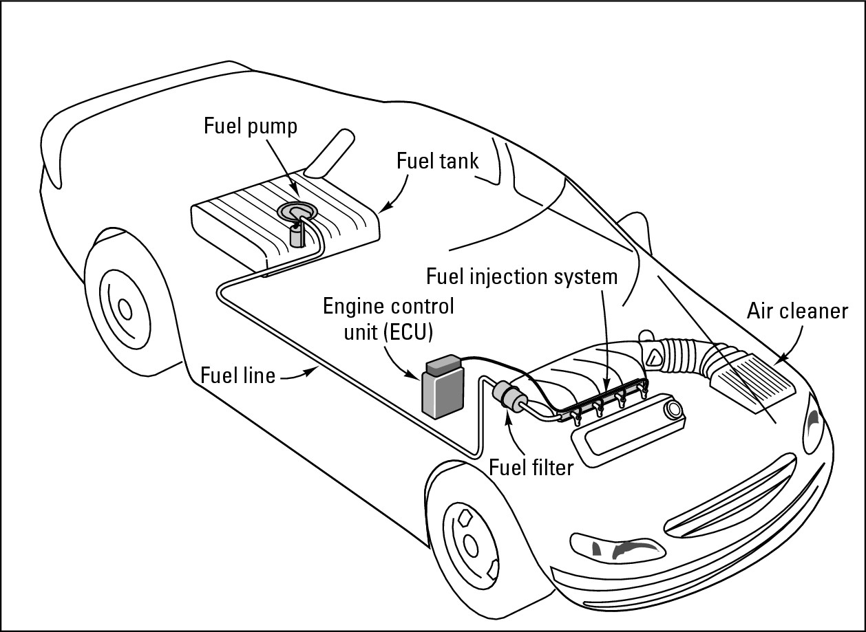
This chapter introduces you to a traditional fuel system. The fuel system shown in Figure 7-1 stores and delivers fuel to the combustion chambers of the engine so that it can be burned efficiently. Although most fuel systems have some basic components in common, fuel systems do vary. Most modern vehicles employ fuel injectors to get the fuel to the engine, whereas vehicles built before the mid-1980s usually relied on carburetors. Since many of the basic parts covered in this chapter either are common to both systems or do the same jobs as their counterparts on carbureted vehicles did, this chapter is relevant no matter which type of vehicle you have.

In this chapter, I trace the flow of fuel from the fuel tank to the engine block, through the exhaust system, and out of your vehicle. When you know what each component does and where to find it, it’s easy to see how all the parts work together to provide your vehicle with “GO power.”
If a picture is worth a thousand words, actually looking at — and maybe even touching — something is worth a thousand pictures. So, if possible, take this book out to your vehicle, open the hood, and visit with the parts of the fuel system as you read about them.

Basic Fuel System Components
Whether your vehicle is more than 20 years old or just 20 days old, has fuel injectors or a carburetor, it probably has the same basic parts in its fuel system with one exception: On modern vehicles, the fuel system — along with most other systems — is controlled by the engine control unit (ECU). The ECU controls the fuel/air mixture and other fuel system operations based on inputs from a mass air flow meter, a throttle position sensor, and an oxygen sensor. As you can see in Figure 7-1, it’s located under the hood.
|
Figure 7-1: A fuel system. |
|
Fuel tank
The fuel tank is a metal or plastic composite container that’s usually located under the trunk compartment (refer to Figure 7-1), although some vehicles have some fairly interesting alternative locations for it. If you’re not sure where your fuel tank is and you can’t find it just by looking under the car, your owner’s manual or mechanic can show you where it’s located.
Inside the fuel tank is a little float that moves up and down as the fuel level in the tank increases or decreases. The float is at its highest when the tank is full. Its position relative to the top of the tank is picked up by a sensor that sends an electronic signal from the tank to the fuel gauge on your dashboard so that you can tell when you have to buy more fuel. (Chapter 8 tells you why you should always try to keep your fuel tank full.) Although some vehicles run on diesel fuel or alternative fuels, the ones I talk about in this chapter are gasoline-powered, so I may refer to fuel as gasoline.
Fuel lines and fuel pump
The fuel pump (see Figure 7-2) pumps fuel through the fuel lines that run under your vehicle from the fuel tank to the fuel injectors (or to the carburetor on older vehicles). Engines with fuel injection use an electric fuel pump that may be located in or near the fuel tank. (On most carbureted vehicles, a mechanical pump is under the hood.)
|
Figure 7-2: An electric fuel pump located in a fuel tank. |

|


Fuel filters
Fuel filters do exactly what their name implies — they filter impurities out of the fuel. As the fuel passes along the fuel line on its way to the fuel injectors (or carburetor), it passes through the principal fuel filter. A small screen inside this filter traps the dirt and rust that would otherwise foul up your injectors.

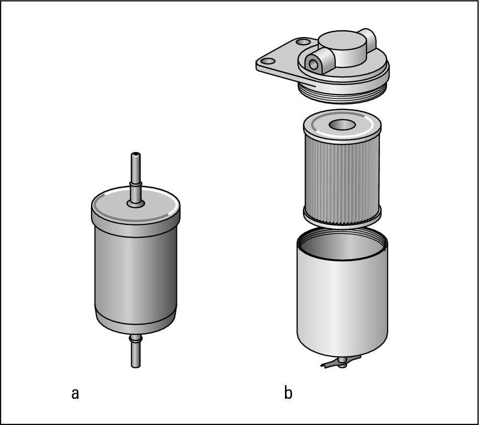
There’s usually a filter screen inside the fuel tank, and some vehicles have additional fuel filters inside the fuel pump, between the fuel tank and the fuel pump, and at the entrance to the throttle body. Figure 7-3 shows two types of fuel filters.
|
Figure 7-3: External (a) and spin-on (b) fuel filters. |
|
.jpg)
Cold air collector box and air filter
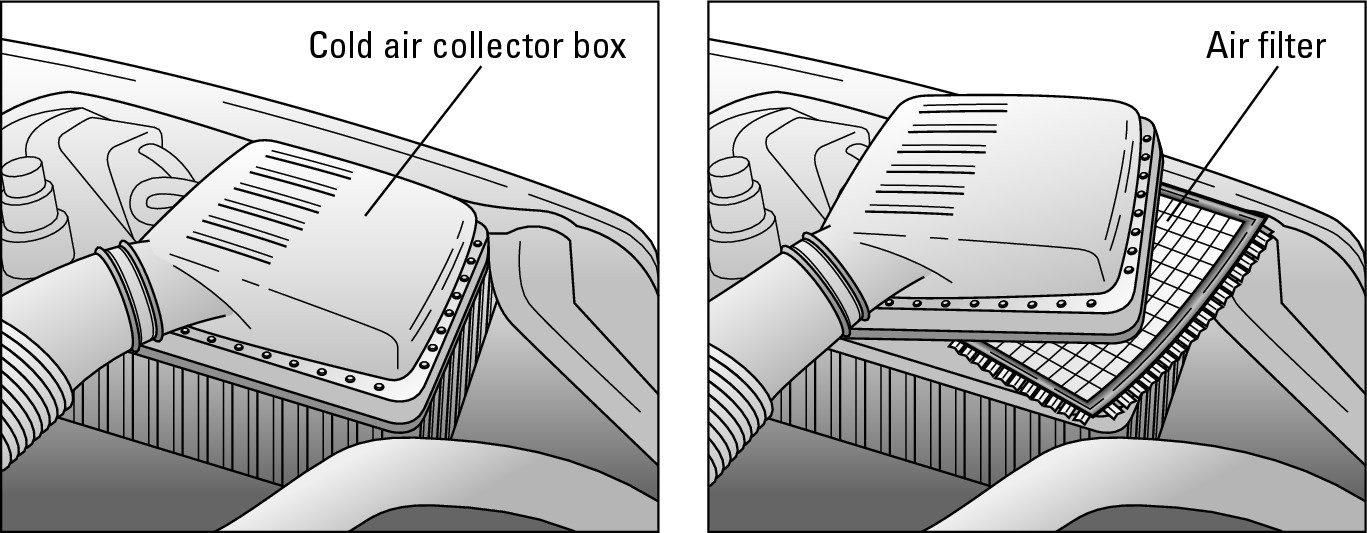
Because gasoline engines run on a mixture of air and fuel, the air has to be cleaned before it’s mixed with the fuel. The air filter removes dirt and dust particles before they can enter the combustion chamber. In the “olden days,” most air filters were inside large, round air cleaners that sat on top of the carburetor. Today’s fuel-injected engines have a rectangular air filter inside a cold air collector box located near the front of the engine compartment; see Figure 7-4.
|
Figure 7-4: The cold air collector box houses the air filter. |
|
To find the rectangular cold air collector box in your vehicle, pop the hood and follow the large air intake duct away from your engine. If you have an older vehicle with a large round air cleaner, you can’t miss it. If you don’t know how to get the hood of your vehicle open, see Chapter 1 or your owner’s manual.

The intake and exhaust manifolds
After being filtered in the cold air collector box, air bound for the engine flows through the air intake manifold. This chamber usually is found near the top of the engine; it holds the air under vacuum and admits it into the combustion chamber with the proper amount of fuel. After the fuel/air mixture is burned in the engine, another set of manifold pipes, called the exhaust manifold, carries carbon monoxide and other waste gases away from the engine through the exhaust system for disposal. You usually find the exhaust manifold either lower down on the same side of the engine as the intake manifold or on the other side of the cylinder head.
The fuel/air mixture
In case you’re wondering why air is such an important fuel system component, it’s because liquid gasoline won’t ignite on its own. The pressure caused by the rapid expansion of burning gases is what drives the engine. The only way to get gasoline to ignite is to mix it with air — hence the need for the fuel/air mixture.
.jpg)
.jpg)
Following Fuel through the Fuel Injectors
Just about every new vehicle is fuel-injected. (The last carbureted vehicles came off the assembly line in 1990.) Although they’re more expensive to service than carburetors were, fuel injection systems with computerized electronic sensing devices have shown sufficient sensitivity, accuracy, and dependability to repay their cost with better performance, greater fuel economy, cleaner exhaust emissions, and more controllable power. Some of the newest models are reported to be 95 to 100 percent clean-burning! Innovations in design are constantly producing cheaper and more durable systems.
Basically, fuel injection systems inject fuel at precisely the right time and place for it to mix with air and form the fuel/air mixture that drives the engine. This section follows the fuel and air through the fuel injection system to the cylinders.

Today’s engines use electronic fuel injectors that are controlled by transistors in the ECU known as injector drivers. The ECU relies on feeds from a variety of sensors to tell it the following:
 How much air is flowing in through the air intake system
 The pressure of the air in the
intake manifold
 The engine
coolant
temperature
 The engine speed
 The
throttle
angle
 The amount of oxygen in the exhaust gases
The ECU’s injector driver uses all this information to figure out just how much fuel to spray into each cylinder to mix with the air to get the optimum power to drive the piston.
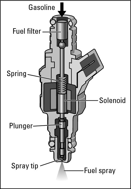
A transistor turns the injector on by completing a circuit to allow electric current to flow through a solenoid in the injector. A spring-loaded valve in the injector opens, and fuel is injected into the engine cylinders. The amount of time that the ECU keeps the current applied to the injector is known as the injector pulse width . The ECU controls the fuel/air mixture by controlling that pulse width, changing the pulse width to make the mixture richer or leaner based on the information it gets from the various sensors.
You can find fuel injectors (see Figure 7-5) in one of two places: Modern multi-port injection systems are located in the intake port just ahead of the intake valve. The earlier throttle-body fuel injection systems are located inside the throttle body assembly (surprise!), which is kind of like an electronically controlled carburetor. The following sections explore each of these injection systems in detail.
|
Figure 7-5: Anatomy of a fuel injector. |
|
Multi-port fuel injection
Most modern vehicles have multi-port fuel injection (MFI) with a separate fuel injector for each cylinder. This system mixes the fuel and air together right in the intake port for each engine cylinder just ahead of the intake valve.
Here’s how multi-port fuel injection systems work:
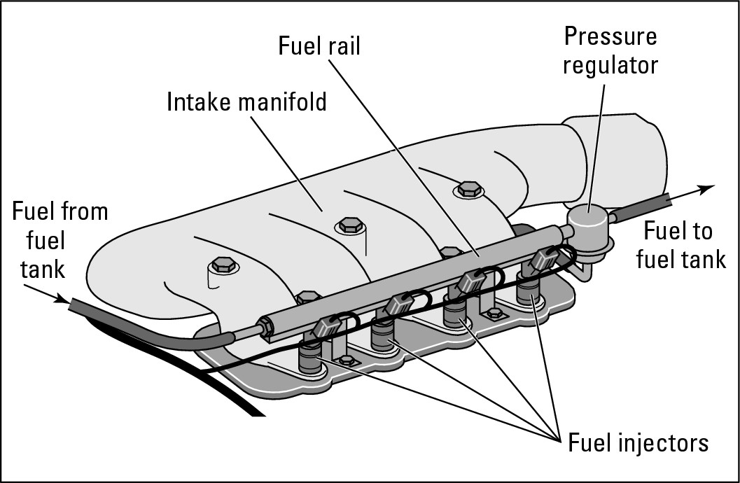
1. An electrical fuel pump pumps fuel from the fuel tank through a fuel filter to the fuel rail assembly, which carries fuel under pressure to the fuel injectors (see Figure 7-6).
The fuel rail assembly also may contain the fuel pressure regulator, which maintains proper fuel pressure and meters unused fuel back to the fuel tank. Fuel injectors, one for each cylinder, are attached at one end to the fuel rail and at the other end to the intake port in the engine.
2. A whole bunch of sophisticated sensors measure a variety of factors and send messages to the ECU, which decides how much fuel to inject at any given time.
These sensors are so perceptive that they even check the weather; how much weight you’re carrying in the vehicle; and whether you’re starting up, speeding up, slowing down, or idling at a light. This information makes the system respond faster and results in greater fuel economy than older vehicles achieved with throttle-body fuel injection (described in a later section).
3. The ECU completes the electrical circuit to the injector solenoid for the proper injector pulse width, and fuel under pressure is injected into the intake port just before the intake valve.
|
Figure 7-6: Fuel flows through the fuel rail to the injectors. |
|
Sequential fuel injection
More recent fuel-injected engines feature sequential fuel injection (SFI) in which the fuel injectors fire in sequence rather than all at once. Because each injector opens individually just before its intake valve opens, the fuel is always sprayed right into an open port and therefore stays in suspension. This type of system is more efficient than a system whose injectors fire simultaneously. (For example, if you have a six-cylinder multi-port fuel-injected engine that’s simultaneously fired, three of the six injectors are pulsed together, and then the other three injectors are pulsed.) In addition, emission levels are lower in an SFI system, but the system requires a separate electrical circuit for each injector.
Gasoline direct injection
The gasoline direct injection (GDI) system is relatively new in the United States but is expected to grow more popular as time goes on. It resembles diesel technology (see Chapter 9) but uses gasoline instead of diesel fuel. Instead of being mixed with air to form a fuel/air mixture prior to injection, the gasoline is injected directly into each engine cylinder. The ECU uses data from various sensors to time the injection of the fuel into the cylinder and regulate the resulting fuel/air mixture for maximum efficiency under varying driving conditions.
Although a gasoline direct injection system is currently more expensive to build than a standard engine, it measures fuel so precisely that you get the most bang for the buck. However, to handle its higher emission of NOx emissions (nitrogen oxides), the GDI system requires a more costly catalytic converter than a standard engine does. Because of the greater fuel efficiency, automakers are currently working on gasoline direct injection systems to reduce their emissions and bring down the cost. As fuel becomes more expensive and the efficiency of these engines increases relative to the costs, they’ll become more popular and more widely available.

Improvements to fuel injection systems
Two exciting ways that fuel injection systems are being perfected is the replacement of moving parts with stationary ones and solid parts with intangible substances. By reducing the number of mechanical parts, car manufacturers hope to reduce production costs and create devices that are less susceptible to breakdown due to physical stress.
Now, I’ve been in favor of simplification ever since my mother taught me to always buy the washing machine with the fewest gadgets on the principle that the fewer parts involved, the fewer things there are that can break down. But I keep having this fantasy that if they continue to replace mechanical car parts with miniaturized and computerized equipment, eventually I may lift the hood of my vehicle and find nothing but a little black box! At that point, when things go wrong, I’ll probably have to seek the services of a wizard rather than a technician!
The upside is that using less metal, plastic, and rubber places less strain on the world’s dwindling supply of raw materials. It also reduces the amount of energy consumed by production (as well as driving) and the number of disposal facilities required to process all the worn and broken stuff that gets thrown away. So let’s hope that the trend continues, wizards and all.
Throttle-body fuel injection
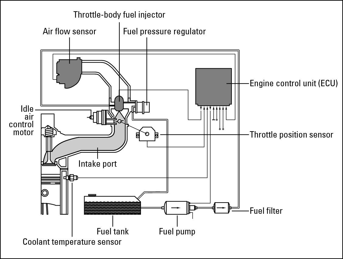
Throttle-body fuel injection (TBI) was the first fuel injection system to become popular as carburetors were being phased out. This system is less complicated than the multi-port fuel injection systems found on more recent vehicles (refer to the preceding sections), but it’s also less efficient. Instead of using individual fuel injectors to pump the fuel into each cylinder, the TBI system mixes the fuel and air together right in the throttle assembly of the vehicle. Along the way, sensors monitor air flow, throttle position, temperature, and other factors and report back to the ECU (engine control unit). You can see the parts of this system in Figure 7-7. Some of these systems use solenoids to spray the fuel into the airstream in the throttle through a fuel injector nozzle.
If you have a vehicle with throttle-body fuel injection, here’s how it works:
1. An electrical fuel pump pumps fuel to the throttle body assembly. The throttle body assembly looks similar to a carburetor and houses the fuel injector(s) and a fuel pressure regulator.
2. The fuel pressure regulator maintains proper fuel pressure and meters unused fuel back to the fuel tank.
3. A computer controls one or two fuel injectors mounted in the throttle body assembly. The computer applies electrical current to the injector solenoid for the proper duration (called the injector pulse width ), and fuel under pressure is then injected and mixed with air as it passes through the throttle on its way to the engine.
|
Figure 7-7: The throttle-body fuel injection system. |
|
The Engine Block: Where the Fuel System and Ignition System Meet
Whether accomplished through a fuel injection system or a carburetor, after the air and fuel unite in the form of a vapor and the spark plugs are ready to provide that all-important spark of ignition, all that’s needed is a spot for that passionate meeting to take place. The rendezvous occurs in your engine’s cylinders, and it’s truly a triumph of timing (as any successful rendezvous must be!).
In this section, I describe the major parts of the engine and explain how they create the power that drives your vehicle.
Major engine components
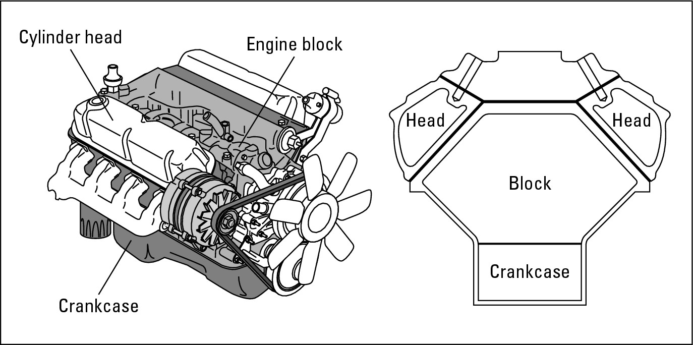
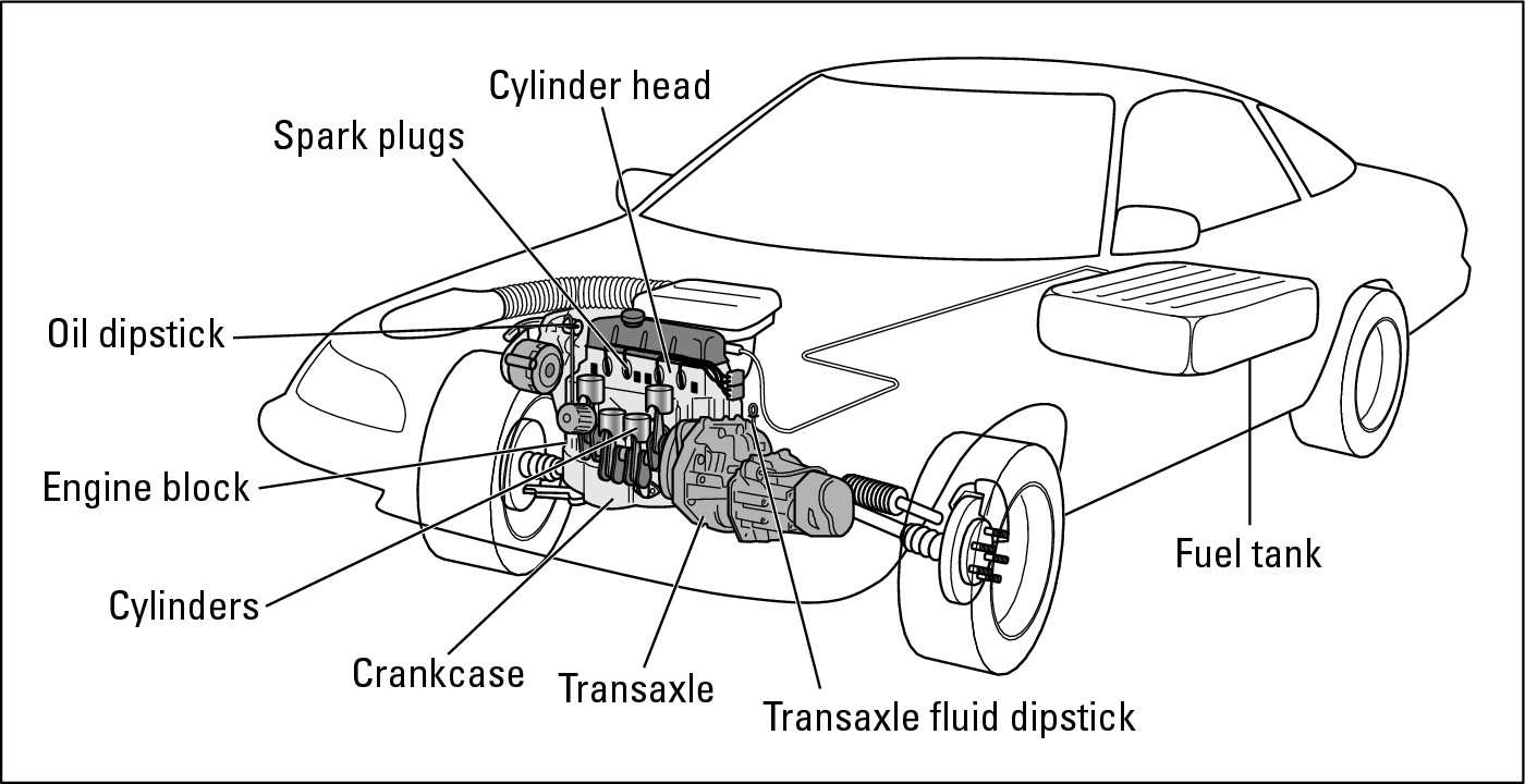
Inside the engine are several fascinating parts, which you can see in Figure 7-8.
At the top are the cylinder heads. These contain the mechanisms that allow the valves to open and close, letting the fuel/air mixture into the cylinders and allowing the burnt exhaust gases to leave. Below the cylinder heads is the engine block itself. This piece contains the cylinders, which contain the pistons.
|
Figure 7-8: The main parts of an internal combustion engine. |
|
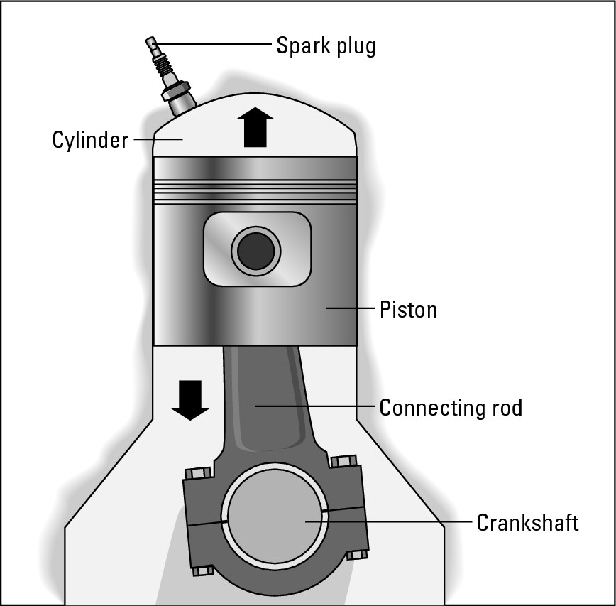
So what’s a cylinder? It’s a hollow iron pipe that’s capped at one end and has a spark plug inserted into and through that cap so the plug’s electrodes are available for action (see Figure 7-9).
|
Figure 7-9: Anatomy of a cylinder. |
|

|
Figure 7-10: The main parts of a transverse internal combustion engine. |
|
Engines that have a single row of cylinders are called in-line engines (sometimes called straight engines). V-type engines have two parallel rows of cylinders set on an angle to each other. On rotary engines (found on some Mazdas), there’s a single large internal chamber inside which a three-lobed, or triangular, rotor revolves. The rotor makes an eccentric or uneven revolution, continually forming smaller chambers in which occur the same four-stroke power cycle as in a conventional internal combustion engine (the next section describes the four-stroke power cycle).

Inside each cylinder is a metal piston that fits snugly against the walls of the cylinder so that nothing can get past it. On the outside of the piston are piston rings that ensure a snug fit. The cylinder also has other openings besides the ones for the spark plug and the piston. These are for the intake valves and the exhaust valves.
At the bottom of the engine is the crankcase, which houses the crankshaft and the oil pan. Coolant circulates throughout the engine to keep it cool, and oil circulates to keep the parts moving freely.
Now that you’ve met the “players,” you’re ready to get on to the main event in which they play their roles: the fiery meeting of air, fuel, and fire known as the four-stroke power cycle.
The four-stroke power cycle
The piston rides up and down inside the cylinder on a connecting rod that attaches to the crankshaft, causing the crankshaft to turn. Each movement of the piston is called a stroke. Four strokes — down, up, down, up — complete the cycle that creates the power to drive the engine. This process is aptly called the four-stroke power cycle. The four-stroke power cycle varies slightly depending on whether your vehicle’s engine is a conventional internal combustion engine or a diesel engine. I cover the conventional internal combustion engine in this section and the power cycle in diesel engines in Chapter 9.
Here’s what happens on each stroke of the piston in a conventional internal combustion engine:
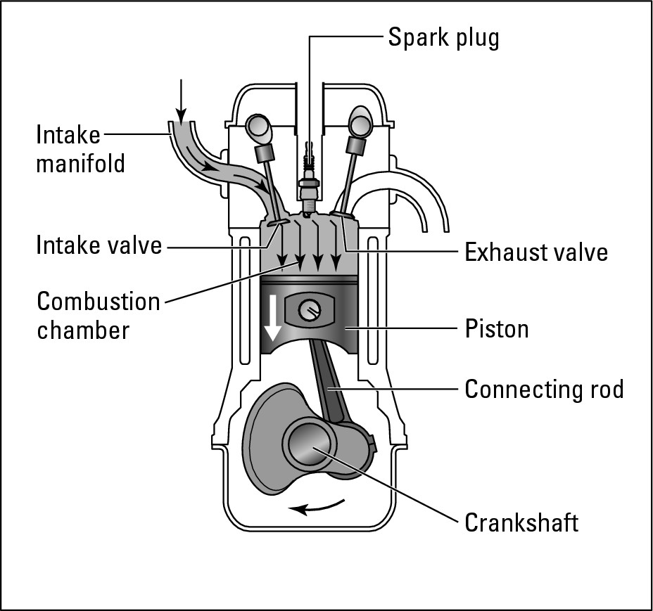
1. Intake stroke: See Figure 7-11. When the piston moves down, it creates a vacuum in the top portion of the cylinder (where the piston was at the end of its last upstroke). Air can’t get in from the bottom of the cylinder because the rings on the piston seal it off. Then the intake valves, conveniently located in the cylinder head, open up and let the fuel/air mixture into the cylinder. This mixture rushes in to fill the vacuum left by the piston.
|
Figure 7-11: The intake stroke. |
|
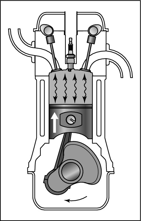
2. Compression stroke: See Figure 7-12. The piston moves back up, compressing the fuel/air mixture into a tiny space between the top of the piston and the top of the cylinder. This space is called the combustion chamber and also happens to be where the end of the spark plug enters the cylinder. The difference between the total space inside the cylinder and the space inside the combustion chamber is called the compression ratio. It indicates that the pressure has been raised from normal air pressure of 15 psi (pounds per square inch) to hundreds of psi, which makes the resulting explosion much more intense.
|
Figure 7-12: The compression stroke. |
|
At this point, the intake valves have closed, so the compressed mixture can’t get out. (The intake and exhaust valves create airtight seals to ensure that nothing can get past them when they’re closed.)
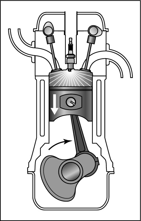
3. Power stroke: See Figure 7-13. The spark plug produces a spark across the gap between its electrodes. This spark ignites the compressed fuel/air mixture. Then the burning fuel/air mixture ignites, creating intense pressure that forces the piston down again. The power that pushed the piston down is transmitted, via the connecting rod, to the crankshaft. It then travels, via the drive train, through the clutch or torque converter, the transmission, the driveshaft, the differential, and so on to the wheels. (A quick overview of this process appears in Chapter 4.)
|
Figure 7-13: The power stroke. |
|
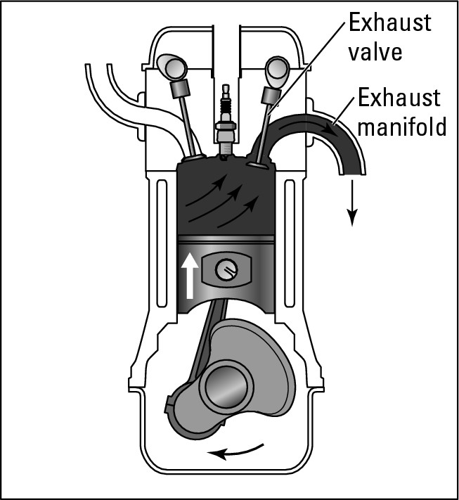
4. Exhaust stroke: See Figure 7-14. The piston moves up again, pushing the burned gases up with it. Then the exhaust valve opens and lets the burned gases out into the exhaust manifold. From there, the burned gases travel through the exhaust system (which includes antipollution devices), through the muffler, and out the tailpipe into the environment.
|
Figure 7-14: The exhaust stroke. |
|
The cylinders don’t fire all at once. To keep the engine properly balanced with all that action going on, they fire in a particular order called the firing order. So while one cylinder is going through the intake stroke, another will be at the compression stroke, and so on. The firing order varies from one engine to another, and Chapter 5 has descriptions and illustrations of the firing orders for a variety of engine types.
When you understand the four-stroke power cycle it’s easier to see why the diagnostic inspectioins and service required by your warranty are so important. Spark plugs are checked and replaced because, if the spark is insufficient or the timing is off, the result is less power and incompletely burned fuel. Increased air pollution and fuel consumption are high prices to pay for stretching the intervals between spark plug replacements, especially because they’re much less frequent than before! Chapters 6 and 8 show you what you can do to help keep your electrical system and fuel system in tune.
Supercharging with Turbochargers
A supercharger is a pump that compresses the intake air and forces it into the cylinders of a gasoline-powered car. Because superchargers are usually belt-driven by the engine (instead of being driven by recycled exhaust gases as a turbocharger is), they consume engine power to increase engine power. Because they’re not fuel-efficient, they’re generally used only to increase the speed of “high-performance,” low-efficiency vehicles. Supercharging shouldn’t be confused with turbocharging.
Turbocharging means to use a turbine — powered by the engine’s waste gases — to force greater amounts of air into an engine’s cylinders. This process produces more power in both diesel and conventional vehicles because they run on a greater volume of air and fuel. The more air the engine can take in, the bigger the bang during the power stroke of the four-stroke power cycle. At first, cars were turbocharged to perform better on racetracks, but when automakers began to put smaller engines in larger vehicles to lighten their weight and conserve fuel, turbocharging provided a way to increase the engine’s power so that these bigger vehicles wouldn’t be sluggish on the road.
Here is how turbocharging works:
1. The hot exhaust gases leave the exhaust manifold, but instead of going directly through the exhaust system and out of the vehicle via the tailpipe, they first pass through a turbine, which is just a fan that’s set in motion by the expanding gases.
2. A shaft connects the fan to a compressor, which blows fresh, filtered air into the cylinders. (On a carbureted vehicle, the compressor takes the fuel/air mixture and blows it into the cylinders.)
3. The excess and used exhaust fumes pass from the turbine to the exhaust system and continue on their way to the tailpipe and out into the air.
The more load on the engine, the hotter and faster the exhaust fumes that turn the turbine. The faster they turn it, the more air the compressor sends to the engine and the more power the engine can produce. This unique way of converting exhaust gas energy into mechanical power has a nice merry-go-round effect.
Sounds simple, doesn’t it? Well, usually the first thing an engineer learns is “The simpler, the better,” or as the Zen monks put it, “Less is more.” (From engineering to philosophy in a couple of paragraphs! Maybe I ought to change the name of this book to Zen and the Art of Auto Maintenance.)

Check out Chapter 9 for more about diesels, especially the new environmentally friendly innovations that have turned diesel-driven vehicles from potential causes of cancer into efficient eco-friendly vehicles. The innovations also are turning overburdened garbage dumps into recycling opportunities.
The Exhaust System
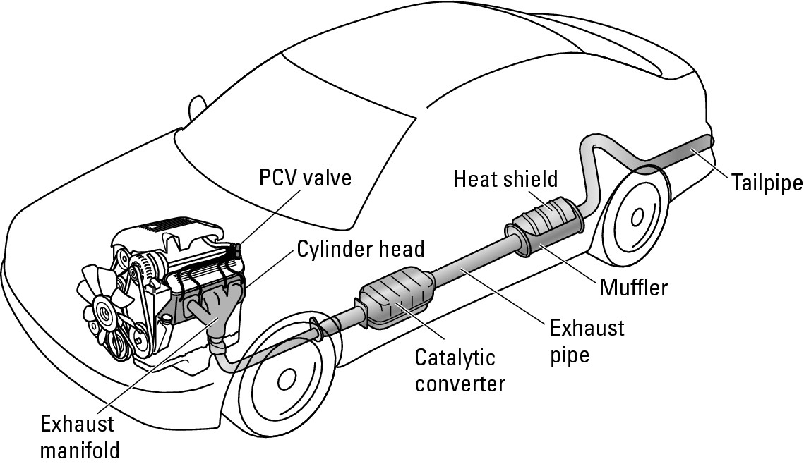
The exhaust system, shown in Figure 7-15, is the waste disposal system of your vehicle. When the fuel system brings the fuel and air together in the cylinders to drive the vehicle, waste products are formed, and some of them are toxic. This section deals with how the exhaust system works to detoxify or reduce these toxins before they’re released into the environment.

As the exhaust gases pass from the cylinders in the engine through the muffler to the tailpipe at the rear of the vehicle and into the air, emissions-control devices — including the PCV valve, various sensors, a catalytic converter, and other components — work to reduce or remove the harmful substances and recycle unburned fuel vapors.

The following sections explore each of the major parts of the exhaust system in . . . exhaustive? . . . detail.
|
Figure 7-15: The exhaust system. |
|
The muffler
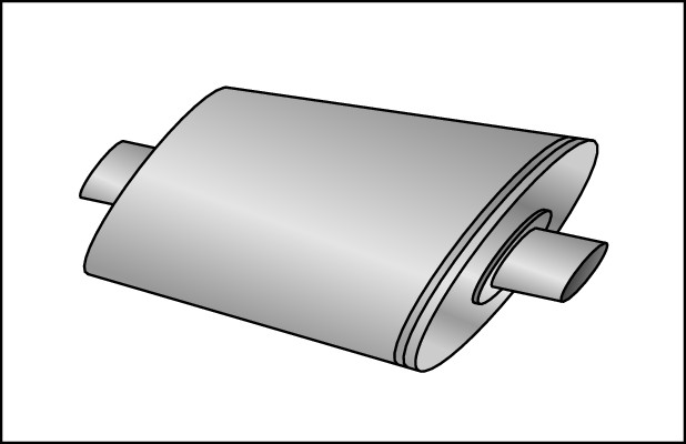
Exhaust pipes carry what’s left of the exhaust gases through a muffler, which controls the noise of the escaping gases to the tailpipe and out of the vehicle (see Figure 7-16). If it fails, you can get a ticket, probably for disturbing the peace! Besides keeping the noise down, the muffler also has an effect on the pressure required to pass the exhaust gases through it, which creates the “back pressure” that the engine requires to run efficiently and affects the temperature and therefore the efficiency of the catalytic converter.
|
Figure 7-16: The muffler. |
|

The PCV valve
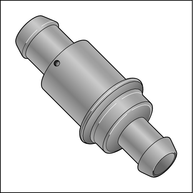
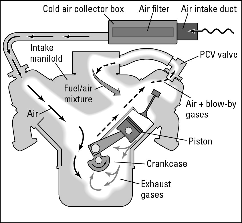
The PCV valve (shown in Figure 7-17) is part of the positive crankcase ventilation system, which reroutes unburned gases, or blow-by, from the crankcase to the intake manifold and back to the engine, where they can be reburned in the cylinders. This process cuts the amount of pollution released into the environment. It also increases fuel economy because unburned fuel in the blow-by is consumed the second time around. The PCV valve also extends the life of the engine by reducing the water vapor and acid deposits that contaminate oil and form engine sludge. Figure 7-18 shows you how the PCV valve works.
|
Figure 7-17: A PCV valve. |
|
|
Figure 7-18: How a PCV valve works. |
|
The catalytic converter
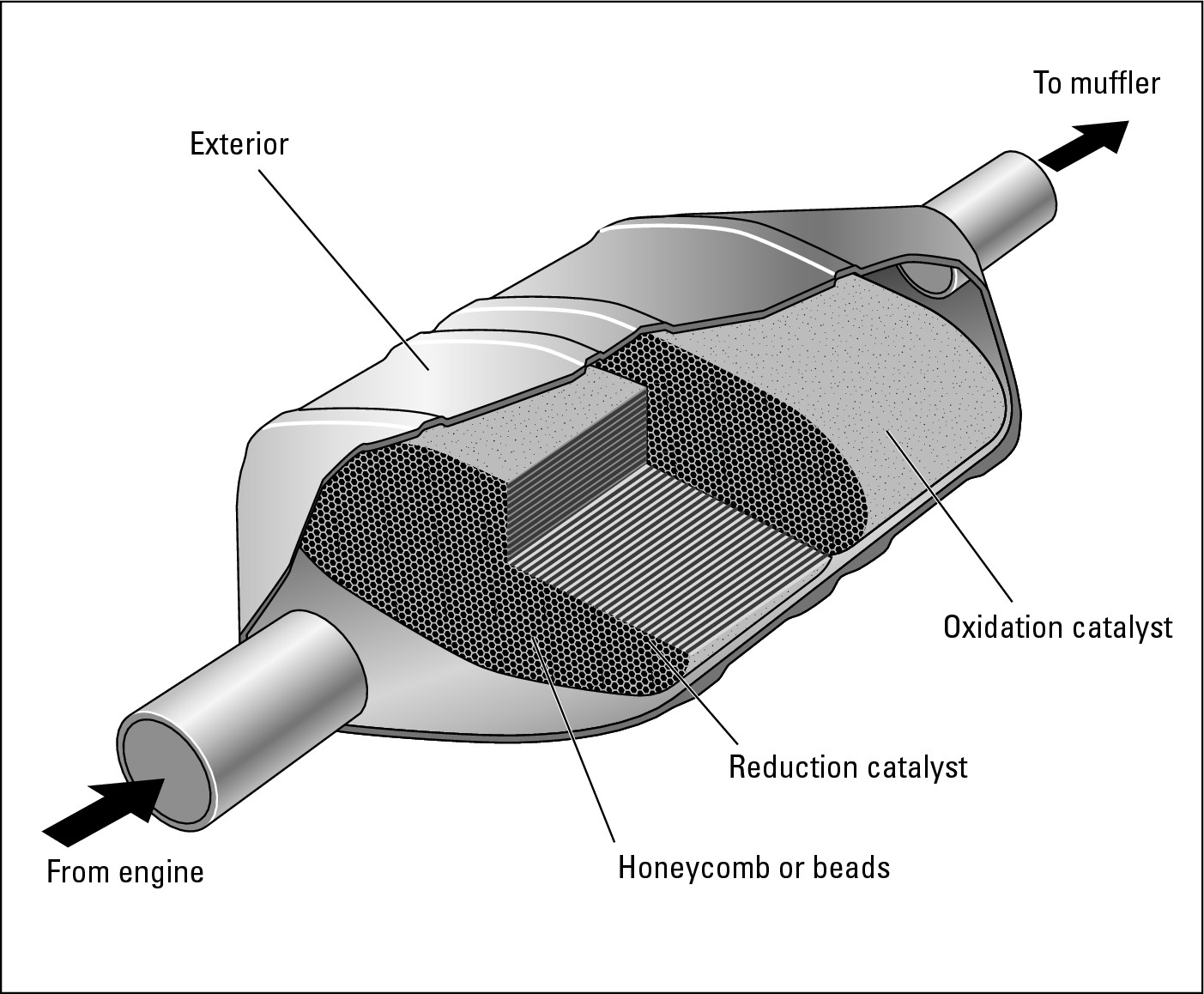
The catalytic converter (shown in Figure 7-19) is usually attached to the exhaust pipe just after the exhaust manifold pipes. It was developed to deal with smog by further reducing the toxic substances in the exhaust gases before they can pollute the air. The catalytic converter is basically a cylinder filled with either little ceramic beads or a honeycomb structure coated with minute amounts of expensive metal catalysts that interact with the pollutants:
 Reduction catalysts (rhodium and palladium) turn the
NOx
(nitrogen oxide)
emissions
to oxygen and nitrogen, which exist in the air we breathe.
 Oxidation catalysts (palladium and platinum) turn carbon monoxide and hydrocarbon into harmless carbon dioxide and water.

|
Figure 7-19: Interior and exterior views of a catalytic converter. |
|
Other emissions control devices
Other emissions control devices include an exhaust gas recirculation system (EGR). An EGR valve on the intake manifold allows a small percentage of the exhaust gases back into the intake manifold, which lowers the peak combustion temperature in the combustion chambers and results in lower NOx emissions. Also, oxygen sensors tell the ECU about excess oxygen in the exhaust gases so that the ECU can correctly control the fuel/air mixture. Air injection systems and various other gizmos also help clean up the exhaust before it enters the air.
