Chapter 6 - Working With The First Sample Layout Drawing
Stay on the Layout space of 1FAP (AR01:1FAP):
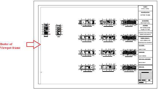
- Delete the old ViewPort frame (if any)
- Select the layer named ViewPort (previously created) as the current layer (this layer is not allowed to print).
- Using the
MV
command, draw a rectangular ViewPort frame in the middle of the print area on the A3 sheet (this ViewPort frame will, of course, belong to the "ViewPort" layer and will not be printed).
- Double-click on the middle of the ViewPort frame to log into the ViewPort space
- Zoom, Pan, find the 1FAP drawing to be displayed, bring it to the middle of the viewport so that your eyes feel that is reasonable.
- Switch to click the
ViewPort Scale
button in the bottom right corner of the screen
- Select the scale drawing according to the ratio of dimensions and text note of 1FAP. Suppose is 1:75
- Double-click on the screen to exit ViewPort.
- We can click on the border of ViewPort, drag to narrow or expand the view.
- If you find some notes text, size lines or text in the Block is lost (not displayed) displayed, you must exit the ViewPort click space, set the system variable
ANNOALLVISIBLE
= 1.
- After feeling that the drawing is properly arranged in the ViewPort frame, we need to lock that ViewPort frame to avoid when we scroll the mouse, the aspect ratio of the frame will be changed. To lock ViewPort frame: we select the frame border / Right-click /
Display Locked
/ Yes.
ViewPort frame after locked, can not change the ViewPort Scale rate, we can Zoom, Pan comfortable objects inside ViewPort without fear of scaling.
- We can Move, Copy ViewPort, the commands to work with Layer (layon, layoff, ..) are implemented as Model.
- To create one more ViewPort, you can use
MV
↙ command to draw or copy from existing ViewPort. However, I encourage:
"1 Layout should only put 1 ViewPort frame showing 1 plan drawing only"
In case the details on the drawing that you want to show are not large, you still want to put multiple views on a layout and those views have different ratios and their drawings on the model have broken lines. The math is this: How do the ViewPort frames, even though they are different, but after printing the paper, the density of the dashed line is still uniform across the drawing (printed on the paper you are holding)?
Sir, I have anticipated this situation and have worked out the plan for you from the beginning, but you probably don't know it.
The workaround is to tick the box "Use paper space units for scaling" so that the dashed lines are always in sync with all viewport ratios. After printing out the paper, the dashed line has a uniform thickness/thickness across the whole drawing, looking very nice and not distracting.
Checking here is equivalent to setting
PSLTSCALE
= 1 (make sure that
MSLTSCALE
= 1). Therefore, I asked you to set these 2 variables to the first value, now you understand.
- Type the command
LT
↙
Note:
If you don't see this box, click
Show details
.
- The processing of drawing printing is proportional and has dotted lines on the Layout other than printing on the Model. Therefore, it is necessary to have experience and understand the problem, otherwise, it will be difficult to solve thoroughly, because it is a combination involving many variables: PSLTSCALE, MSLTSCALE, LTSCALE and ANNOTATION SCALE (or ViewPort Scale) ).
- If printing on the Model, you do not need to care about: PSLTSCALE, MSLTSCALE, ANNOTATION SCALE, but only need to care about LTSCALE and CELTSCALE. So from the outset, specify the clear idea that you plan to print on Model or Layout space.
Later, I also shared how to handle dashed lines in Layout (of course, with other people's drawings), but don't worry, if you follow my method correctly there will never be any errors and you will be the one to help them troubleshoot. Trust me!