

With this unrestored 1955 Cadillac’s 331-cid V-8 engine out, it was ready to head to the machine shop.
Clouds of smoke from the tail pipes, plus the passage of 50-plus years and 133,000 miles, proved the 331-cid V-8 engine that is the subject of this article was due for a rebuild. From tear-down to turn-key, Old Cars Weekly will cover the basics of the 1955 Cadillac’s 331-cid engine rebuild. And since the car is owned by your editor and his family, the rebuild will stay in the family using only parts and services offered through the pages of Old Cars Weekly.
To start the rebuild off right and in the Old Cars Weekly family, the business of reader Joe Thorn was selected to complete the process. The selection of Thorn’s business, Metal Crafters Inc. of Stevens Point, Wis., was based on reputation and recommendation, and also because of its proximity to the Old Cars Weekly headquarters in Iola, Wis., to aid in documenting the project.
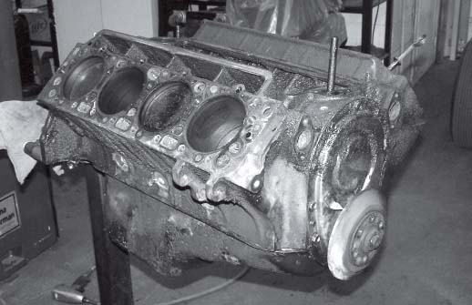
The engine is positioned on a sturdy engine stand to aid in the removal of parts.
Metal Crafters advertises itself as “the most versatile tool and die shop in Wisconsin,” and there’s little doubt to this claim upon walking among the shop’s heavy equipment. The shop can design parts and complete production runs, repair metal and machinery, work with food-grade stainless-steel and offer specialty machine rebuilding services, as well as a complete metal fabrication shop. Most importantly to this series of articles, Metal Crafters offers a complete engine rebuilding shop. Though it specializes in Model A and T Fords, the shop happily rebuilds all types of engines. When the Cadillac’s 331-cid V-8 was brought to the shop, a 1931 Chevrolet six-cylinder and alcohol-injected small-block Ford were undergoing work in the machine shop.
Metal Crafters employee Troy Herman does the bulk of the engine rebuilds at the business and will complete this Cadillac engine. When an engine is dropped off at Metal Crafters, Herman likes to know why the rebuild is necessary. Was it knocking? Did it burn oil? Does the owner just want a fresh engine or more horsepower? (In this case, the ngine burned oil and was simply tired.) It also helps Herman if the owner leaves a factory shop manual for the car at the shop, as the manual contains the engine’s original specifications. The fluids, such as the oil and coolant, should be left at home, though; drain the oil only a short-time before tearing down the engine for a rebuild to ward off moisture.
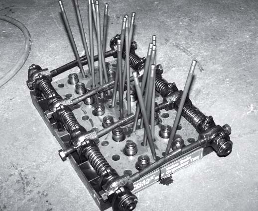
The old rods and lifters are placed in this handy holder to prevent them from rolling around.
When Herman received this 331-cid V-8, it was only partially degreased and some of the accessories were still attached (fuel pump, distributor and water pump). Even though some of these accessories could have been removed before the engine was received by Herman, he said he prefers to receive an engine that is not completely torn down, as it allows him to see first-hand how the engine should be assembled. (This engine was also thoroughly photographed to ensure that it could be correctly reassembled with brackets and bolts in the correct place.)
This rebuild process began using hand tools to remove the basics: fuel pump, water pump, intake and exhaust manifolds and the valve covers, all while the engine was safely secured to a stand. As parts were removed, they and their hardware were labeled, bagged in plastic and placed on a shelf dedicated to this project. Then the rocker arm shafts, push rods and lifters were removed and set in a tray designed to keep these parts in order.
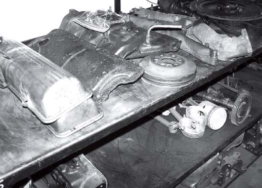
Parts for each project get their own shelf to prevent parts from getting mixed with parts from other projects.
The heads were then ready to be removed. Herman began removing the torqued bolts holding each head to the block by beginning in the center and removing the bolts outward and in a circular pattern. Once the heads were off, they were placed on a shelf for further disassembly with the bolts that once held them on.
Among the parts that required more than a single socket or wrench for removal was the harmonic balancer. To take the harmonic balancer off, a harmonic balancer puller was employed. The tool acts much in the same way as a steering wheel puller, as bolts are fastened to the balancer and a threaded shaft pushes against the crank. Often, an impact wrench is required to pull off the harmonic balancer, but this engine’s nut came off using a hand tool. As with all of the parts he removed, Herman inspected the part for wear. Even though this engine will get a new harmonic balancer, Herman examined the rubber gasket around the harmonic balancer for any signs of wear.

The harmonic balancer removal tool is placed into position. It works much like a steering wheel puller.
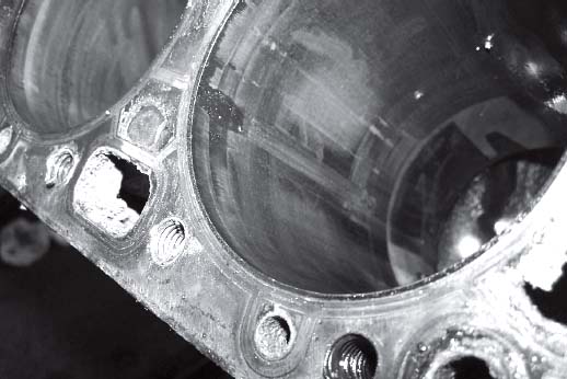
Once the rod caps are unbolted, the pistons can be carefully slid out. With the pistons out, this scoring of the cylinder wall became clear. Such scoring is one of the sources of smoke out the tailpipe.
With the harmonic balancer off, Herman carefully removed the timing chain cover, then the timing chain and timing sprockets, which will be replaced. Since the frost plugs will be replaced, they were simply punched out with an awl to drain any remaining coolant in the engine.
Next, the oil pan was removed and the part and its contents were inspected. In typical fashion, sludge was found at the bottom of the pan, though the sludge was gritty. To check for metal fragments in the grit and sludge, a magnet was run through the sludge, but no material clung to the magnet.
Once the oil pump was removed for rebuilding (a new oil pump was not located for this engine), piston removal could be attacked. The rod caps were unbolted from the underside of the engine while it was on the engine stand and then carefully slid out. Although new rings will be installed, Herman worked to avoid damaging them any further in order to inspect them and identify damage caused from wear, rather than removal. In this case, one broken ring fell off the piston as the piston was pulled out of the cylinder. Upon inspection of the piston, severe wear was apparent where the ring wrapped around the piston. Worn or broken rings, such as this one, are a source for oil consumption, and this engine was burning its fair share.
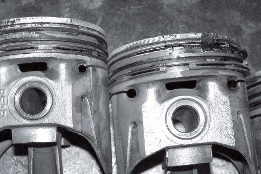
A broken ring ate away at the top of the piston at right, causing excess oil consumption and smoke from the engine.
The bearings in the piston end caps were also inspected for wear. These slick pieces are largely flat semi-circles and ride inside the caps. Worn bearings will have a polished appearance exposing the layers of construction. Poorly worn bearings may have grooves or score marks in them. Unfortunately, this engine had a few shallow score marks.
With the pistons out, the main bearing caps could be unbolted and removed, then the crankshaft could be carefully lifted out. Each crankshaft bearing is a two pieces, held in place by the main bearing car and the U-shaped saddle that the crankshaft rides in (The bearing, of course, rests between the engine and the crankshaft.) Upon removal, the bearing is inspected for score marks, even though it will be replaced. Any score marks offer an indication of the engine’s condition before the rebuild.
After the fuel pump shaft (which rides on the camshaft and activates the fuel pump lever) was slid out and the dipstick tube was removed, the camshaft bearings were ready for removal. To remove the camshaft bearings, a slide hammer was inserted inside the round openings cast in the block for the camshaft and bearings to ride in. This area is a circle-shaped area cast into the block and forming the support for the top and bottom of the camshaft. To remove each bearing, Herman inserted the slide hammer through the corresponding camshaft opening in the block. A lubricated stop was placed on the slide hammer behind the bearing so Herman could gently ram the bearings out of the engine by using the momentum of the slide hammer. The stop is matched to the size of the bearing; any smaller, and it will slide through the opening once occupied by the crankshaft, but any larger and the stop will hit the block, rather than the bearing, and not complete the job. Greasing the stop will allow it to pass through the camshaft opening in the block without scoring the areas it slides through once the bearing comes out.
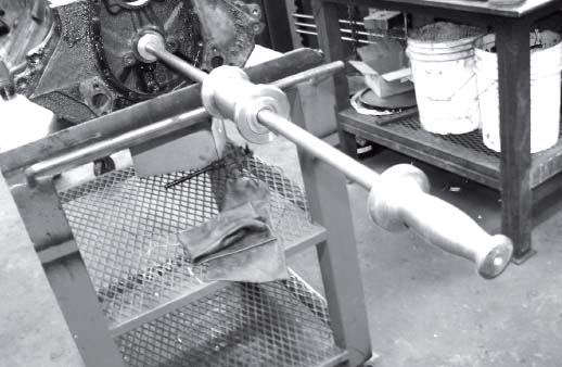
Only the bearings for the crankshaft and the camshaft remain in the otherwise stripped engine block. This slide hammer is placed inside the bearing cavities. A fixed stop is placed behind the smooth, flat bearing, and the stop gently rams the bearing out from behind.
Stripped and ready to be ripped
With the engine completely stripped, it was time to clean the block, heads and every other part that will be reused. The large parts, such as the block and heads, were placed in an oven and baked for six hours at 650 degrees to remove grease, dirt and oil. Old dirt and oil harden and turn to dust, then fall off the parts easier. A shot blaster is required to further clean the engine; it acts as a sandblaster, though it uses fine metal material to blast the block. This metal material can ruin a rebuilt engine if it is not completely removed, so the block is then placed in a cabinet and sprayed in a caustic bath to remove all traces of the metal bits.
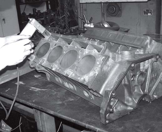
Once the block is completely stripped, it is blasted and cleaned in a caustic bath. With all of the old grease and oil removed from this process, it is magnafluxed. The magnaflux process checks for cracks by placing a red metallic dust and magnet on the block. The red dust fills into the cracks, making the cracks more obvious.

Like the block, the stripped head is also placed in the caustic tank after it is checked for cracks in the magnafluxing process.
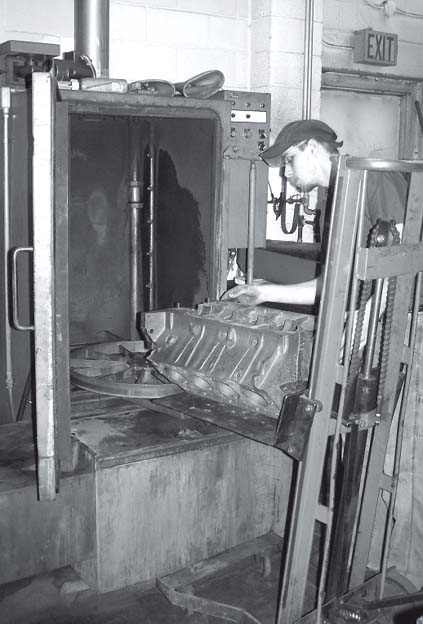
After the magnafluxing process, the block is placed back in the caustic bath to remove the metallic dust. If the dust is not completely removed, it can wreak havoc in an engine.
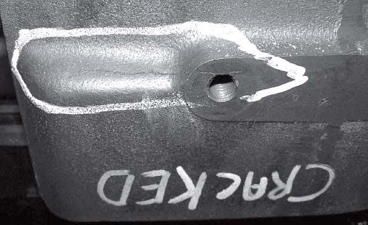
Fortunately, the Cadillac block had no cracks, but this six-cylinder Chevrolet block wasn’t as lucky. After it went through the magnaflux process, this crack became clear.
Inspection time
With the engine block cleaned, it’s nearly ready to expose all of its imperfections. At this point, Herman makes a visual inspection, looking for obvious signs of cracks. He also examines the cylinder walls for grooves and scoring. This engine has a significant groove in one cylinder wall, and shallow scoring in at least three other cylinder walls. As is typical of an engine with many miles, there is also a ridge at the top of each cylinder wall. This ridge represents the small area that the piston does not reach during its throw, so its height remains at or near the original location of the cylinder wall. The large area below the ridge is lower, caused by years and miles of the piston passing over the cylinder wall.
Before Herman develops a plan of attack to machine or re-sleeve the cylinder walls, it must be magnafluxed to identify small cracks that are not visible to the eye. If there are significant cracks in the block, or many small cracks, the block may not be worth rebuilding.
To magnaflux the block, an atomizer is used to spray red magnetic powder on the deck where the cylinder heads are fastened, the front and rear of the block and the saddle, as well as in the cylinders. The magnetic power is applied near an electrified magnet that is moved around the engine to where the powder is applied. The powder will gather into any cracks with the magnet nearby, and the concentration of red powder in the cracks makes them obvious. Fortunately, this engine passes the magnafluxing test with flying colors, as no cracks were exposed.
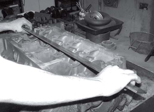
A machinist’s straight edge is placed in the saddle where the crankshaft rides to check for warpage of the block.
Since the magnetic red dust is actually little pieces of metal shavings, they must be removed in the caustic tank. If the dust is not completely removed, it can wreak the same havoc on a rebuilt engine as the metal material in the shot blaster. Once the clean engine is removed from the caustic bath, Herman checks the deck and saddle for warpage with a machinist’s straight edge. The straight edge is laid across these parts at various angles and positions and Herman searches for gaps between the engine and the straight edge. Again, this engine block passes the test, making it a good candidate for rebuilding.
Unfortunately, the cylinder heads, which were rebuilt just 6,000 miles ago, will need to be rebuilt. To tear them down, Herman used a valve spring compressor to contract the springs and remove the keepers that hold the springs in place. The keepers sit inside of a retainer, and in some cases, the keepers stick inside the retainer. When the keeper sticks, a deep socket that goes over the valve and keeper can be placed on the retainer. The socket on the retainer can be struck with a hammer to loosen the keeper inside the retainer, while not affecting the valve and keeper. With the keepers out, the retainers, springs and valves can be removed. In case these parts will be reused, they are kept in order so that the parts can be re-installed in the same position from which they were removed.

This pneaumatic tool compresses the valve spring, thus removing stress from the keeper that holds the spring in place. With the spring compressed, the keeper can be easily removed, thereby releasing the spring.
After the valves were removed from the cylinder heads, the bad news continued when it was discovered that some of the valve guides were cracked, so these will need to be replaced while rebuilding the heads. It was also clear that this engine did not have hardened valve seats and stainless-steel valves to accommodate unleaded fuel and new stainless-steel valves. The stripped heads can now be cleaned in the same manner as the block, and then examined for cracks and warpage. According to Herman, it is common for heads to crack between valve openings, but these heads are in excellent shape.
The engine is now ready for the next step: machining and determining the sizes required for ordering new internal parts.