

Anyone can tear apart an engine down to its bones — block, heads, manifolds, etc. — but it takes a pro to complete the next step: machine work.
Machine work is necessary to ensure the engine block, heads and other external engine parts have flush surfaces, such as manifold openings, so that these parts can be reunited without fluid or air leaks. Machine work also opens such areas as cylinder walls, crank bearing openings and other spaces within the engine to an exact dimension that the rebuilder chooses (much larger dimensions for performance applications, slightly larger for stock applications). This allows the moving internal parts of an engine (pistons, crank, etc.) to be installed within these areas to an exact gap or tolerance, measured in thousandths of an inch. If the specific tolerances stated in factory manuals are not followed, parts with too little gap may not move freely, while parts with too large of a gap will move sloppily and cause damage.
Machining also smooths the surfaces of engine parts by wiping away scoring or other blemishes to allow gaps between the engine and its moving parts, and also makes these gaps a consistent measurement. In this case, the machine work undertaken on a 331-cid overhead-valve V-8 from a 1955 Cadillac will bring the engine back to factory specifications as closely as possible. This engine will receive new pistons, crank bearings and camshaft bearings, and a rebuild will be undertaken on the heads to make them compatible with unleaded fuel.
Boring the block
To make an engine’s internal surfaces even, square and smooth, material from the engine must be removed in the machining process. Since engines have tight tolerances for space between parts, the material that is removed to make a surface flush must be replaced to maintain an engine’s correct specifications, whether it’s with oversized bearings or pistons. If not, the parts will move and shift within the engine and it will be destroyed.
For this Cadillac 331-cid V-8, the machining started with the crank, because any work on the crank affected the size of other parts, particularly the crank bearings. After its removal, the crank was inspected by Troy Herman, an employee of Metal Crafters in Stevens Point, Wis., where the engine rebuild was undertaken.
Herman began by measuring the diameter of the crank and comparing it to the diameter stated in the 1955 Cadillac shop manual to determine if the diameter had reduced through years and miles of spinning. While the diameter of the crank checked out to factory specifications, small grooves were found where the crank rode in the bearings. This meant the crank needed to be turned until the surface was smooth. This work was sent to another shop that specializes in turning crank shafts, and after the shop reported that it machined off .010 inches from the surfaces of the crank that ride in the bearing, Herman ordered oversized crank bearings. Oversize bearings were necessary because the crank of an engine spins along insert bearings that are placed between a saddle in the block, forming the top half of a perfectly round cradle for the crank, and the crank caps, which are the bottom of the cradle. With some surface material removed from the crank to smooth out the area in which the crank makes contact with the bearing, the bearings had to be larger to compensate for the missing diameter of the crank. This would prevent the crank from spinning sloppily in this space.
With the crank out of the engine, Herman also installed the crank caps to check for taper and an out-of-round condition in the cavity formed between the engine saddle and the crank caps. Such wear to this area is caused by worn bearings or a worn crank, resulting in the crank moving too much in the saddle. The condition of the saddle was checked in three places to ensure that the space in the saddle was straight and consistently even so when the crank is re-installed, it will not prematurely wear the new bearings or itself get wrecked.
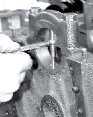
Troy Herman of Metal Crafters in Stevens Point, Wis., measures the area between the engine saddle and the crank shaft caps with a telescoping gauge. This is the area where the crank shaft and its bearings go. Since the crankshaft was turned to remove mild scoring from the surfaces of the crank where it makes contact with the bearings, the bearings will be larger than stock (oversize) to make up for this loss. Simply put, the dimensions of the smaller crank diameter and the larger crank bearings must add up to the original size for these parts to maintain factory tolerances.
Cutting away cylinder walls
The size and taper of the cylinders was also checked using a dial-bore gauge adjusted in conjunction with a micrometer, and they were also examined for an out-of-round condition. Herman used a tool to measure the diameter of the cylinder in several areas at the top, bottom and center. On average, this engine’s cylinders were .003 to .005 inches off, a relatively small amount reflecting the fact the cylinders had never been bored and the pistons didn’t cause excessive wear to the cylinder walls.
On this engine, a ridge remained at the top of the cylinder as the pistons do not rise all of the way to the top of the cylinder. Where the pistons do pass on the cylinder walls, they remove material through years of rising and falling as the engine turns. To make the cylinder the same diameter from top to bottom, this ridge will be bored down, as will the remaining lower portion of the cylinder walls, to the same dimension. Herman estimated he would need to bore the cylinders down .020 inches to remove the ridge and scoring in each cylinder with a boring machine. Not all of the scoring to the cylinder walls was removed at this bore size, however, so he bored it to the next size of .030 inches.

The engine block is lined up in the boring machine to bore out each cylinder to the desired diameter. Only .010 inches amount of cylinder wall is removed with each pass until the desired bore is attained.
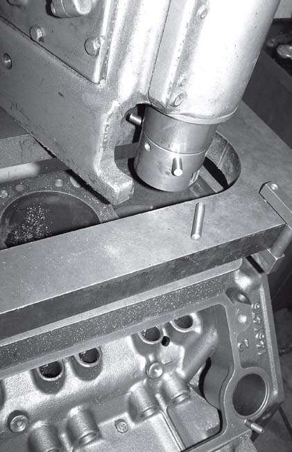
Locating pins on the boring bar center the boring bar in the cylinder.
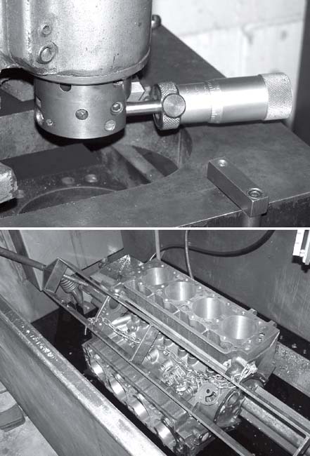
The engine is placed in an oil bath for the honing process. Honing the engine will take .002 inches off the cylinder walls and bring the cylinders to their final size and diameter. The oil in the tank lubricates and cools the hone.

The honing stone (pictured in the cylinder) has a silicone carbide tip and is run up and down the cylinder wall to leave a cross-hatch pattern.
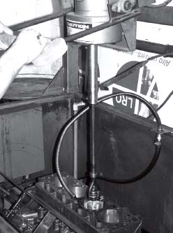
While the hone spins, it is dragged through the cylinder to leave a cross-hatch pattern. The dimensions of the cylinder are checked at several points during the honing process to ensure the correct amount of material is removed from the cylinder walls.

Honing leaves a cross-hatch pattern on the cylinder walls, which ensure proper compression for the pistons that will eventually pass through.
Because the tolerance or space between the piston and cylinder wall must remain at the factory specification, larger (or oversize) pistons were employed to fill the space gained by boring out the cylinders. Fortunately, pistons for this engine come in a standard bore, .020 and .030 over, so Herman was able to match the new cylinder size with the proper .030 pistons.
Before boring each cylinder wall, Herman measured the diameter of the new pistons’ skirts to determine their diameter. He then compared the width of each piston skirt to the size he calculated the cylinder wall would be after boring and honing to ensure the factory tolerance of .002 inches between the piston and cylinder wall would remain.
To bore each the cylinder wall, a floor-mounted boring bar was placed through the exact center of each cylinder and locked in position with three locating pins while the engine rested in a boring machine. A cutting tool with a carbide insert was then run through the cylinder wall, removing .010 inches of cylinder wall with each pass, stopping just short of attaining the desired cylinder diameter.
Before finally boring each of the eight cylinder walls to the desired diameter, Herman stopped short to allow for the material that will be removed in the next step of honing the cylinder walls. Honing leaves a desirable cross-hatch pattern to the cylinder walls, and although it’s not as abrasive as the boring process, honing still removes iron from the cylinder walls (about .002-.003 inches). While honing the cylinder walls, a constant stream of oil is poured through the cylinders to cool and lubricate the honing tool as it scuffs the cylinder walls.
Removing too much material from the cylinder walls would result in the need for even larger pistons, and only so much material can be removed from the cylinder walls before their strength is compromised, so Herman constantly checks the dimensions of the cylinder walls with a dial bore gauge throughout the boring and honing process. In addition to size, the gauge also measures taper (a variation in diameter from the top to bottom of the cylinder wall) and roundness (an egg-shape to cylinders with a larger diameter at the center of the cylinder compared to the top and bottom). Neither taper or roundness should exist at the end of the boring and honing process.
After the boring and honing process has left the cylinder walls at the desired diameter and with a cross-hatch pattern, the engine is cleaned in a caustic bath to rinse away any of the metal particles removed in the process. If particles remain, they will damage the engine as they enter the oil. This step also removes the oil used in lubricating the honing tool. Before the engine is ready for the next step, Herman prefers to tap out threads throughout the engine, then clean the engine with soap and water. The engine block is then bagged in plastic in preparation for the next step involving the block: assembly.

A close-up of the dial-bore gauge’s gauge.

This is the tip of the dial-bore gauge, used to measure the diameter of the cylinders.

This dial-bore gauge is used to measure the diameter of the cylinders at the top, bottom and center. The dimensions should be the same at all three locations.
Guiding the heads
The previous article on this engine rebuild covered the disassembly and inspection of the heads for warping and cracks, and the parts were found to be in good, rebuildable condition. However, before machine work could begin to install hardened intake and exhaust seats for unleaded fuel, as well as new valves and springs, the pressed-in valve guides needed to be removed.
Before the valve guides were removed with a punch, they were inspected. There was something suspicious about several of the guides. The outside of them was cracked or broken away, though the inside of these guides remained solid. It was determined that a previous machinist had drilled out the center of the original guides and inserted new guides in the center of the old valve guides, perhaps when the heads were rebuilt about 6,000 miles ago. The original guides became thin and began cracking away, leaving a mess and certainly metal parts floating around the crankcase.
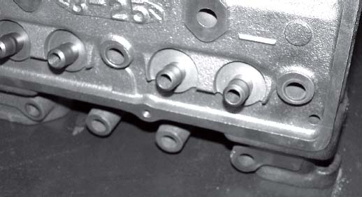
After the original valve guides were punched out,
new valve guides were pressed into place.
Once the guides were punched out, Herman immediately test-fit the new guides to verify their size and fit in the head. One of the cavities in which the valve guide was to be pressed was found to be .005 inch too large. As a result, an oversize valve guide that retained an internal diameter at the factory specification was special-ordered. With Metal Crafters’ extensive machining equipment, the shop could also machine an existing valve guide to fit this engine application, if necessary.
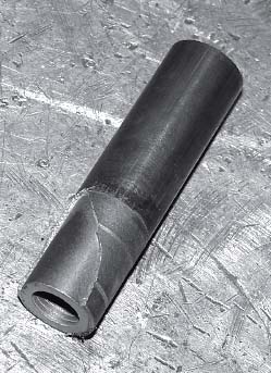
A previous machinist cleared the inside of the original valve guides and inserted new valve guides in them. The process left too little material on the original valve guides, causing them to crack and break away. This damaged valve guide was punched out of the head.

Herman measures the depth of the area he has cut from the head for the hardened valve seat. The area cut away from the head must match the depth of the seat. However, the diameter of the opening must be .005 inches smaller than the seat so it can be pressed in place and not move.

The valve guide and seat machine is employed to bore the head for the installation of hardened valve seats. The valve seat is much like a ring, but must sit deep in the head and be flush with the top of the head.
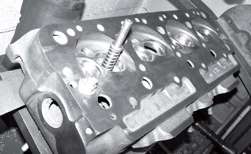
To ensure the boring bar is at the center of the valve opening,
a guide is mounted on the machine.
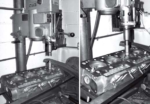
A carbide cutter riding around the guide in the valve opening cuts away at the cylinder head until the desired amount of material for the hardened valve seat. After each pass, Herman measures the depth of the cut to ensure he does not remove too much of the head.

The valve openings in the head are shown here. The inside surface of each valve has been polished somewhat to remove burrs and increase engine efficiency. Performance seekers will completely smooth these openings through polishing to increase the efficiency of the valves.
To install hardened intake and exhaust valve seats, a portion of the head surface must be removed so that the deeper valve seats can be installed flush with the head surface. For this procedure, Herman uses a valve guide seat machine for this machining. The bore is measured to be .005 inches smaller in diameter than the new valve seat to ensure the seat remains in place after it is pressed in the head.
A guide is then placed inside the exhaust or intake valve opening in the head to center the bit. After ensuring the bit is in the center of the opening, it is slowly lowered into the head. Herman removes only a little of the surface of the head with each pass, and frequently checks the depth he’s removed from the head surface so that he does not remove too much of the head. Once the amount of head surface removed matches the depth of the new valve seat, the area is ready for the seat to be pressed in with a punch. Lock-Tight is also applied to the seats at this point as an extra measure to ensure they remain in place. Once the seat is installed, its surface is machined smooth to match the valve passage way, thus creating less turbulence as the valves open and close during the air intake and exhaust sequence and helping the engine run more efficiently.
The right rods
In this engine rebuild project, the original rods were going to be reused, so they were examined to make sure they were straight and without any twist to their shape, and also to ensure they are not out-of-round or worn.
To check for twist, the rods were placed in a rod alignment instrument with the piston pin attached to detect any gaps between the rod and the instrument. Any gaps indicate a bent rod, but a flush alignment shows a straight rod that can be reused.

An arbor press is used to press out wrist pins, which will separate the piston from the rod.
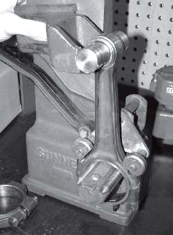
Each rod is placed in an instrument to check for bends or twists in the rod. Any uneven gaps between the rod and the instrument indicate a bad rod. If a rod passes the test, it will be reused.

Each rod cap and rod end are placed squarely against a grinder to ensure the surfaces are completely flat when the two parts are reunited. This process collapses the space between the rod and rod cap. Here, a rod cap is shown in the grinder.
As he does with all the parts, Herman noted the original location of each rod and rod cap in each cylinder so they could be returned to their respective cylinders.
Next, an arbor press was used to remove the wrist pin holding the piston and rod together. The end of the rod (where it meets the cap) and the top of the car cap (where it meets the rod) were each run against a grinding stone to smooth off the ends where these parts meet. Removing material collapses the circular opening formed by these parts where the crank rides. Herman removed .001 to .002 inches from the end of the rod and the rod cap, which will make the opening for the bearing smaller, but also ensure each surface is flat. To compensate for making this rod bearing opening smaller, he also honed the opening between the rod and rod cap upon which the bearing rides, thus returning the size of the area to the factory specification so the bearing will fit again. Once measurements were taken of the opening, and this area between the rod and rod cap measured at the original specification, bearings of original specification were ready to be installed.
To install the new pistons on the engine’s original rods, a rod oven is used to expand the rod end. The heat temporarily expands the opening so a wrist pin can be inserted. Once the opening heats up enough to allow the wrist pin to slide in, the part is inserted and allowed to cool, thus locking the wrist pin in place.

Once the rod end and rod cap are ground square, they are reassembled and placed in a honing machine. This machine will hone out the center of the rod end to the original diameter, allowing original-size bearings to be installed.
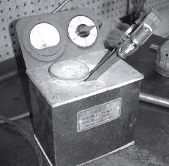
A rod oven is used to heat the rod to make inserting the wrist pin easier.
At this point, the pistons and rods were ready to be mated, and assembly of the block could begin.
SOURCE:
Metal Crafters, Inc.
2701 Chamber St., Stevens Point, WI
715-341-3461