5
Work-energy Theorem: Principle of Finite Element Method
5.1. Work-energy theorem
5.1.1. Hypotheses
This is a solid S:

Figure 5.1. Definition of the initial and deformed states. For a color version of this figure, see www.iste.co.uk/bouvet/aeronautical.zip
State 1 is what is called the initial state (or stress-free state), which is free from stress and state 2 is the deformed state, which is under the effect of external forces.
We adopt the following hypotheses:
- – the gravity is neglected (otherwise state 1 would not be stress-free);
- – the behavior is assumed to be linear elastic;
- – both the external heat exchanges (heat input, etc.) and internal heat exchanges (no friction, etc.) are neglected;
- – the external forces are applied infinitely slowly between 1 and 2 (hence, there is no inertia);
- – the displacement and the strain are small (SPH) and it does not affect the directions of the external forces.
5.1.2. Strain energy
The kinetic energy theorem between states 1 and 2 is written as:
In other words, the sum of the work of external and internal forces on S between the states 1 and 2 is null and equal to the sum of kinetic energy variations and its potential energy between states 1 and 2. In short, the energy is conserved!
Hence:
Therefore, the work of external forces is equal to the stored energy in 
This relation is equivalent to the first law of thermodynamics:
Integrated between states 1 and 2, neglecting the heat exchanges:
So, once again, the internal energy variation  in the solid between 1 and 2 is equal to the work of the external forces and, in particular, does not depend:
- – on the behavior law of the material;
- – on the way in which the external forces are applied.
In particular, in the mechanics of deformable solids, the internal energy only depends on the strain state.
If we also choose u1 = 0, then:
And Ed is called the strain energy (in J).
5.1.3. Work of external forces
If we consider n external forces applied at points P1,…, Pn, with the displacement u1,…, un, then the work of external forces is written as:
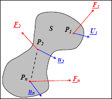
Figure 5.2. External forces. For a color version of this figure, see www.iste.co.uk/bouvet/aeronautical.zip
Of course, in reality, each up(t) continuously moves from 0 to up and each Fi(t) moves continuously from 0 to Fi. Moreover, the behavior of the structure is linear:

Figure 5.3. Linearity of external forces. For a color version of this figure, see www.iste.co.uk/bouvet/aeronautical.zip
So:
And therefore:
5.1.4. Strain energy
By using the analogy with the work of external forces, we define the strain energy by:
Or, in its developed form:
In this relation, the role of the force is played by the stress and the role of the displacement is played by the strain.
The triple integral on volume impresses, but simply signifies that all of the points of the solid are added up.
EXAMPLE: TENSION.–
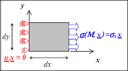
Figure 5.4. Tension test. For a color version of this figure, see www.iste.co.uk/bouvet/aeronautical.zip
In order to imagine this, we will apply it to the tension example. Evidently, we have:
- – Calculation of the work of external forces:
On the faces with normal vectors ±y and ±z, the external forces are null, so the work is also null. On the face with normal vector x, the force is in the x-direction and the displacement is null according to this direction so the work is null. Hence:
where Fx is the force in the x-direction and ux the displacement in the x-direction of the face with normal vector x.
And the strain energy is worth:
Hence:
In conclusion, it works (the work of external forces is definitely equal to the strain energy), and the expression of strain energy can even be demonstrated in this way by working on the stress tensor, component by component.
5.1.5. Energy minimization: Ritz method
We are looking to approximately solve the following problem:
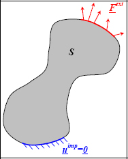
Figure 5.5. Setting the problem. For a color version of this figure, see www.iste.co.uk/bouvet/aeronautical.zip
So, at each point M, we look for the stress, strain and displacement fields.
As it is generally not possible to solve the problem exactly, we shall solve it approximately. Therefore, we look for the displacement in a pre-defined form:
where the function f is a known function that depends on the parameters c1, c2,…,cn which are unknown.
We have therefore reduced the search down to n parameters, rather than a search for three unknown functions; the three displacements (in 3D). Evidently, the problem is simpler, but the drawback is that the form of the function f is assumed a priori.
If this function is properly chosen and there are a set of parameters representing the exact solution of the problem, then we have:
If the exact solution is not in this form, then the difference:
will be minimum for the best choice of parameters c1, c2,…,cn. In fact, we can show that this difference must necessarily be positive and null for the exact solution.
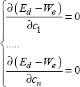
The relations:
enable us to determine these parameters.
So, the energy minimization enables choosing the best function among all the functions that you have given yourself. The advantage is that you will definitely have a solution, but the disadvantage is that if the set of functions that you have chosen is far from the exact solution, then this minimization will give you the one which is least bad: which is not necessarily a correct one!
5.2. Finite element method
5.2.1. General principle of finite element method
The principle of the finite element method is to discretize the real problem in simple domains on which the displacement field is a simple function (called the basis function or the interpolation function) of displacements in nodes (edges of the domains).

Figure 5.6. Discretization of the structure in finite element method. For a color version of this figure, see www.iste.co.uk/bouvet/aeronautical.zip
So, if we have n nodes:
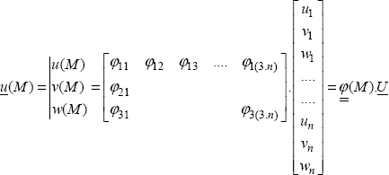
where  represents the matrix of the basis functions, which depends on M, but it is totally known, and U represents the displacement vector at nodes, and therefore corresponds to the parameters to be determined, i.e. c1, c2,…,cn from the previous section.
Then in order to determine the strain field, we derive the displacement field, so the basis functions  can be expressed as:
where the notation ε(M) corresponds to the strain components placed in the column:
NOTE.– we note γxy rather than εxy, which will enable us to obtain the strain energy by making a scalar product with the stress vector.
This strain notation in the form of a vector is evidently mathematically false; it is just a notation to simplify the scripts. In particular, the classic properties of vectors (for example, the rules on rotation) do not apply to the strain which is definitely a matrix!
And  corresponds to the derivative matrix of the basis functions
  ; evidently as the vector U is constant, its derivative is null.
Then we determine the stress:
As with the strain, the stress vector is:
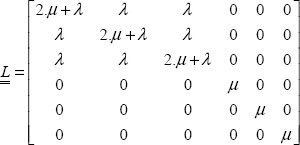
And  is the rigidity matrix:
which enables us to obtain the behavior law introduced in the previous chapter.
Then we calculate the strain energy:
Hence:
with  being the rigidity matrix of the whole structure:
This matrix obviously does not depend on the point M and represents the entire behavior of the structure. We can show that it is a square and diagonal matrix whose size depends on the number of nodes chosen.
The work of external forces remains to be calculated:
where the vector F is the vector of the external forces on the nodes where the forces are applied, and 0 elsewhere.
The minimization of the energy therefore gives:
Hence:
and
Knowing that U is the unknown:
In conclusion, to solve a problem with the finite element method, you must start by modeling your boundary conditions in force and in displacement. As a matter of fact, in practice, we do not know them precisely and the engineer’s job is to choose the boundary conditions for his or her model, which represent the real boundary conditions as best as possible. This stage is essential and often very delicate!
We then discretize the structure in elementary sub-domains. Once again, this approach is not simple and it is laden with consequences as it largely conditions the quality of the final results. In general, the greater the number of nodes, the more precise the solution will be, but this is not always true. However, this poses the problem of the calculation time, which increases with the number of nodes.
We then select a behavior law, and once again, we need to make the wisest approximation possible.
Finally, what remains is to perform the calculation per se, of which the largest part consists of inverting the structure’s rigidity matrix.
5.2.2. Example of the three-node triangular element
Let us put this in 2D and consider a triangular finite element with three nodes: 1, 2 and 3. There are six unknowns in the problem, namely the displacements to the three nodes: u1, v1, u2, v2, u3, v3:
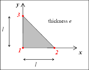
Figure 5.7. Triangular finite element. For a color version of this figure, see www.iste.co.uk/bouvet/aeronautical.zip
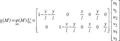
We choose a linear displacement field which enables us to find the value of the displacements at the nodes:
Or even:
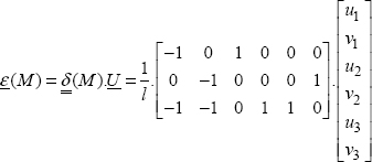
We can then determine the strain field:
Or even:
Here the matrix  is constant, but it is obviously a particular case.
We then determine the stress and then the rigidity matrix of the structure (I am going to skip a few lines of calculations):
This is a symmetrical matrix that needs to be inverted in order to determine U.
If, for example, we look at the following problem:
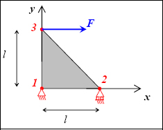
Figure 5.8. Triangle subjected to a force. For a color version of this figure, see www.iste.co.uk/bouvet/aeronautical.zip
Here, we therefore have:
We incidentally notice that these boundary conditions enable us to block all rigid body displacement field, and that the solution will therefore be unique.
We have:
And
Then:
Hence:
Hence, the following displacement field:
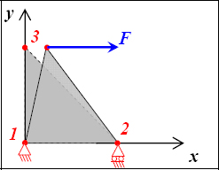
Figure 5.9. Displacement field of a triangle subjected to a force. For a color version of this figure, see www.iste.co.uk/bouvet/aeronautical.zip
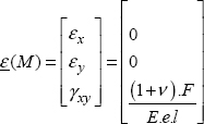
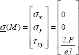
And:
In short, only the point 3 is displaced in the x-direction, and we have the creation of a shear strain, as well as that of a shear stress. The value of this stress is equal to the force F divided by (e.1/2), or the section of the plate at mid-height.
If you are interested, you can re-do this very simple problem on a finite element code, such as Catia. You can, for example, follow the guide given in the next section.
If we now pose the problem of an applied force on a plate in this way, we will obviously find a more complex displacement field. This is due to the fact that the discretization adopted here imposes a linear displacement field. If, on the other hand, we choose a finer grid, we will then obtain a more realistic displacement field:
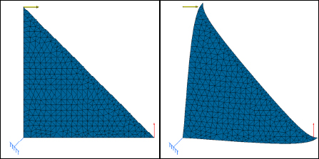
Figure 5.10. Triangle subjected to a force and displacement field obtained by FE calculation. For a color version of this figure, see www.iste.co.uk/bouvet/aeronautical.zip
And the stress fields are also more realistic:
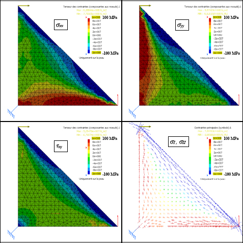
Figure 5.11. Stress field determined by FE calculation in a triangle subjected to a force. For a color version of this figure, see www.iste.co.uk/bouvet/aeronautical.zip
Be careful; despite the fact that the external force and the boundary conditions are applied in points, the stress will tend to infinity as the grid is refined! In short, this result is available only far away from the boundary conditions; this is Saint-Venant’s principle.
Physically, the principal stress diagram is very instructive. In the central part, we mainly observe shearing, or equal principal stresses of opposite signs at +45° and −45°. We also observe a significant compression force on the line going from node 2 to node 3 and significant tension on the lines going from nodes 1 to 2 and 1 to 3.
In conclusion, in order to design this structure, it would be worthwhile for us to put a plate in the central part so as to withstand the shear and beams on the three sides of the triangle so as to withstand the tension and compression forces.
5.3. Application: triangle with plate finite element using Catia
The problem is as follows:
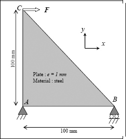
Start by opening a “Part Design”, open a “Sketch” in the (x, y) plane and then create the triangle.
Go to the “Wireframe and Surface Design” and carry out a “Fill” of the sketch. Then, if Catia does not do it automatically, hide (“Hide/Show”) the sketch.
Then apply the steel material (“Apply Material”) by selecting the “Part Body” of your piece.
Go to the “Generative Structural Analysis” module then choose the “Static Analysis”.
Start by applying a surface grid with “Octree Triangle Mesher” (hidden behind “Octree Tetrahedron Mesher”). You can then change the size of the grids by double-clicking on “Octree Triangle Mesh.1” on the “Nodes and Elements” branch of the tree. As there is only one element, choose 200 mm, and if you want to find the example of this lesson, choose the “Linear” elements (the “Parabolic” elements add an intermediary node to the center of each side and therefore enable us to account for a linear stress variation on the element). These (parabolic) elements have to be used absolutely when performing your future finite element calculations with Catia.
Select “2D Property”, then select your grid and fill in the thickness. By default, the material is the one you have attributed to your “Part Body”.
Then apply a “Clamp” at point A. To block the displacement according to Y of point B, choose “User-defined Restraint” then deselect all the settings except that corresponding to Y.
Then apply a force (“Distributed Force”) at C of 1,000 N.
You can start the calculation (“Compute”) by selecting the “All” option if it is not already done, then observe the displacement (“Deformation”).
Catia automatically chooses the scale factor of the deformation. To choose 1 and therefore obtain the displacement in the correct size, go to “Amplification Magnitude”. To obtain the displacement vector of each node, go to “Displacement” (Be careful: Catia automatically changes the scale factor of the deformation back. To block this, tick “Set as default for future created images”).
Select “Principal Stress” (hidden behind “Displacement”), then double-click in the tree on the “Principal Stresses”. Click on “More” then choose “Center of element” in Position. You now have the principal stresses that we have calculated throughout. You can also change the display scale of the stress by double-clicking on the colored scale and changing the maximum and minimum.
To observe the other stresses, after having double clicked in the tree on “Principal Stresses”, choose “Average Iso”, then “Tensor Component”. Then click on “More”, and in “Component” you can choose the three components of the 2D tensor (If you have done a 3D calculation, you will have six components). Ensure that you properly choose the global axis system if it is not already done. To do this, click on the three small dots in “Axis system”, and then choose the “Global” axis system in “Type”.
You can redo the same analysis by changing the grid.


