CHAPTER 6
The Ship, Her Hull, Fittings and Complement
X.1’s Vital Statistics
Surface Displacement was 2,425 tons Standard and 2,780 tons Normal load.
Submerged, X.1 displaced 3,600 tons under Normal load conditions.
She was 363ft 6in (110.79m) long overall, with a maximum beam of 29ft 10in (9.09m), and a mean Normal load draft of 15ft 9in (4.80m).
When necessary, she could carry a maximum fuel load of 452 tons of fuel oil, to give a range of 16,200 miles at 10 knots surfaced; range 18 miles at 4 knots submerged.
The Hull
The keel of X.1, ordered under the Estimates for 1921/22, was laid down at Chatham Dockyard on 2 November 1921. She was built under the covered Ship Shed on No. 7 Slip. Because of her length, some 60ft of the bows protruded beyond the landward doors of the Shed, and the slip had to be extended onto the roadway.
The X.1’s hull was more of a complete double hull than in any previous design. To once more quote the 1921 Technical History Section of the Admiralty, ‘A hen’s egg is strong and so is an ostrich egg, but if the shell of the ostrich egg was as thin as the shell of the hen’s egg it would be very weak indeed; in the same way a “K” boat is structurally weaker to resist deep pressures than is an “E” boat’. And X.1 was to be nearly 30ft longer than the clumsy ‘K’ Boats.
Rear Admiral Dent proposed on 12 March 1921 that her plating should correspond to that of the U 139 class, and the major part of her riveted pressure hull was formed from lin thick high tensile steel (from the Port Talbot Steel Company Limited), annealed to make it easier to roll. This immensely thick hull allowed her to dive to the unprecedented depth of 450ft (A W Johns designed her for a maximum depth of 500ft, as per his note dated 27 February 1922, at which depth he calculated the pressure on the hull to be 225 PSI). This compared with the previous ‘K’ class boats and their ½in plating, which restricted them to a maximum depth of only 150ft. And the new technology brought its own risks. Her thick pressure hull was pierced by the two large-diameter revolving trunks of her turrets. Power-operated rubber glands which sealed these gun trunks were eventually made to operate perfectly. But insufficient hydraulic power to the telemotors meant that she could not free off both gun trunk glands, and open or close her vents, or raise her periscopes all at the same time. These and other minor faults – only to be expected in such a highly imaginative and experimental vessel – were planned to be corrected in the follow-up ship, the X.2, which was never to be built.
The pressure hull was divided up into ten watertight compartments by nine bulkheads, each pierced by a circular watertight door 2ft 9in in diameter – the first such doors to be used in an RN submarine. The entire hull structure was fastened together by rivets – both countersunk and fan heads. In the original design estimates both types of rivet were costed at £1.00 per hundredweight (285kg). Welded construction had been used by Cammell Laird in 1921 to build the merchant ship Fullagar, and it may seem surprising that the technique was not introduced in X.1, given the highly experimental nature of so many elements of her design. However, a major drawback was that the high tensile strength D Quality steel specified for warships was not the best steel to use for welding.1 Welding was introduced into RN submarine designs with the Rainbow class laid down in 1929, which had welded external fuel ballast tanks. Welding was first used for the pressure hull frames with Talisman, Tetrarch and Torbay of the 1938 Programme, while Subtle (launched on 27 January 1944) was the first RN submarine to have a fully-welded pressure hull. Even so, their ¾in thick pressure plating did not permit these later boats to exceed the design depth of X.1.

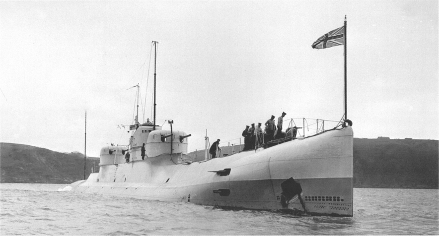
Leaving Grand Harbour, Malta, in June 1928, painted in Scheme III.
Keels
Two 10-ton drop keels were fitted, which could be jettisoned if her crew needed to surface in an emergency. No bilge keels were thought necessary – unlike those which had to be fitted to the Surcouf and the huge Japanese boats. X.1’s rolling characteristics were acceptable as designed.
Weight breakdown
At normal load, the weights built into X.1, as designed, were as follows:
| Tons | |
| Hull | 1,480 |
| guns | 50 |
| ballast keel | 170 |
| battery | 210 |
| ammunition 300 rds | 14 |
| air bottles | 6 |
| main motors | 62 |
| gear & effects | 15 |
| auxiliary engines | 90 |
| water | 24 |
| generators | 36¾ |
| main engines | 250 |
| provisions & stores | 20 |
| torpedoes | 35¾ |
| air bottles | 37 |
| fresh water | 24 |
| trimming water | 10 |
| auxiliary ballast | 20 |
| water in compensating tanks | 40 |
| oil fuel (external) | 177 |
| oil fuel (internal) | 2¾ |
| lube oil | 44 |
| spare gear | 5 |
| 2,781 tons |
Whilst her surface armament, at around 110 tons, represented only some 4 per cent of the total weights, this was much higher than in any other submarine ever built, except for Surcouf. Specific gunnery items were the DCT weighing 16.1 tons, the hull structure and glands underneath the guns at 19.4 tons, and hull stiffening in way of the guns, 3.4 tons. Each turret and trunk as fitted weighed 27.15 tons, and the 5.2in shells and cartridge cases added a further 15.9 tons. The weights for the four sub-calibre barrels and 400 practice rounds are not specified but would have added just under two tons.
Upper control room stiffening
An ex-crew member of X.1, Jimmy Lester, related an ‘exciting’ dive experience in his book More Submarine Memories.2 As he remembered the incident, ‘We heard that she was designed for an extreme depth of 750 feet which sounded unbelievable. On our way to Malta she tried it out. At 450 feet her conning tower reduced its width by 3½ inches so she blew everything a bit quick and surfaced, the Med being very deep just there. All this she told K.26 on surfacing. We were told to keep the near-accident between us as she was secret and experimental.’
From the Ship’s Cover and the papers preserved at Gosport, this may be an earlier incident which occurred during X.1’s first overseas cruise to Gibraltar in April 1926. Apparently, the upper control room had flat parallel sides of such area that, at 400ft there was such serious deflection, it was decided not to stay long at that depth. Commander Phillips reported on 16 April 1926 that ‘Strengthening of the upper control room is “absolutely necessary”, among a list of other items.’
Naval Constructor Mr A G W S Stanton accompanied X.1 on her trip to Gibraltar, and he was able to sketch out a suitable reinforcement for this part of the hull. On his return he drew up a blueprint, which exists in the Ship’s Cover at Woolwich, detailing the following measures:
1. Ribs to be doubled by inserting three new vertical. Z-section 20lbs intercostal welded into bosom of stiffeners;
2. Two horizontal 4in x 4in x 12.751bs stiffeners to be added;
3. 20lbs flanges to be added to both upper floors.
No further comments were heard on the subject of the control room sides, so this frightening incident was not repeated.
The two bow anchors were to be carried in hawse pipes as on a light cruiser – to avoid difficulties in mooring a submarine of such large size.
Fuel and Oil Storage
X.1 carried virtually all her fuel load in external tanks. These were left open at the bottom to allow sea water to enter and replace fuel as it was used up, thus helping to preserve the overall trim. Unfortunately, allowing the fuel oil and sea water to come into contact could lead to the oil emulsifying, especially in bad weather conditions. A much more serious problem was the fact that these external fuel tanks were riveted, and tended to be far from oil-tight.
As early as 19 August 1922, Mr T Palmer, Manager of the Constructive Department at Chatham Dockyard, was defending the yard’s method of sealing the oil tanks, in the following manner:
Oil tank seals use bedding material of vegetable tar and Portland cement. These are mixed to a consistency of common putty and used in association with white hemp stop waters. On testing, if slight leaks occur, a mixture of white and red lead is injected. Considerable experience has been gained at this Yard in oil tight work. In view of the above it is considered that it would be a mistake to depart from Chatham practice at this stage of the construction of s/m X.1.
The reader is left to surmise that there had already been a history of leaks from the external fuel tanks of RN submarines.
On 18 November 1924, Commander Raikes noted that the ‘Rivitting [sic] in No 12 Main Ballast is not oil tight. It was suggested this might be overcome by Electric Welding all the Seams and Butts.’ Obviously nothing was done, since on his return from Gibraltar in April 1926, Constructor Commander A G W S Stanton reported that ‘Nos 1 and 3 Fuel Groups were leaking badly soon after leaving England.’ Again, in July 1928 X.1 reported serious leaks from external fuel tanks (the same problem as with the contemporary ‘O’ and ‘P’ classes). From Lt Commander Ruck-Keene’s report of October 1928 we read: ‘Oil leaks are most serious and in calm weather would undoubtedly give her away when submerged – leaks developed within 3 weeks of leaving dockyard hands. Reports from the Mediterranean Fleet show she was easily visible from the air when submerged.’3 After the Rainbow class were launched with welded external fuel tanks, earlier boats such as Oberon (the former 0.1) had their fuel tank seams welded up during refits. Despite Commander Raikes’ proposal, and the on-going programme of refits, nothing was ever done to improve the sealing of X.1’s fuel tanks, even following her disastrous drydock accident.
Colour Schemes
X.1 carried a variety of paint finishes, and her crew certainly had a great deal of free time in harbour to repaint ship. Given the total absence of specific records on the subject, the following colour schemes are indicative only, based on an analysis of the photographic record and of the Ship’s Log Books. This analysis is complicated by the fact that only a small number of photographs are actually dated, and in some cases these dates appear incorrect. For example, one of the aerial views of X.1 at sea in the Mediterranean is ascribed to ‘4th December 1928’, but her Log shows on that day her crew had gone ashore and the ship was beginning her Annual Refit. Similarly, a scene described as X.1 in harbour in 1931’ shows her in the company of several major vessels, at a time when she seldom left the dockside. Colours actually used are difficult to deduce from black and white photography, but there are pointers elsewhere.
Scheme I
At launch, her hull above the waterline, the casing and conning tower were painted overall mid-grey. This colour was probably the standard Great War submarine grey. The Munsell neutral value was N5/0. A colour and tonal match is the USN Late WWII Neutral Ocean Gray. Below the waterline she was painted the standard anti-fouling red. Initially she had no boot topping. Her pennant number was a large sans serif ‘X.I.’ in white, shadowed in black to the right and below, on the side of the superstructure below the conning tower.
Scheine II
First seen in the photo at No. 1 Buoy, Sheerness (no turret windshields, single forward hydroplanes). The hull above the waterline, the superstructure, conning tower and turrets were overall grey, as were the gun barrels. This was probably the Great War submarine grey. Below the waterline the hull was anti-fouling red, with black boot topping. The depth markings can be seen on her forward hull, painted in white. In fact these numbers were raised metal characters fastened to the hull – probably in brass. She carried a smaller ‘X.I.’ in white, shadowed in black to the right and below, on the conning tower sides. Also in the painting by a crew member. Several bows-on photos show this scheme, as well as the shot of X.1 ‘approaching Gosport’, probably during her torpedo trials.
Scheme III
By June 1928, X.1 had been repainted overall light grey above the boot topping, including her gun barrels, presumably to suit her deployment to the Mediterranean. The appropriate Admiralty Reference for Mediterranean Grey was AP 507C. To eliminate glare from the light grey paint, the top of the DCT, a section of the conning tower roof just ahead of the surface conning position, and the tops of the windshields of both turrets were rendered in a dark colour, probably black but possibly dark grey. ‘X.I’ was in black on the conning tower sides. Walkways along the centre of the hull casing and on the hull aft were a dark colour, possibly black or even covered in corticene, which was a dark red-brown colour.
Scheme IV
Later in 1928 X.1 appeared in a striking scheme: Her hull casing above the boot topping, including the bulbous projection of the bow quick-blow tanks, was painted in a very dark colour. This area is virtually certain to be black. Were it a predecessor of the ‘Mediterranean Blue’ used so successfully by the famous 10th Submarine Flotilla based in Malta during the Second World War, it would more closely match the tonality of the surrounding sea.4 Above this new colour the superstructure sides, conning tower, turrets and gun barrels remained light grey, except for the darker anti-glare panels of Scheme III. ‘X.I.’ was in black on the conning tower sides. This must be considered an experimental scheme, since X.1 did not retain it for long. That the two clearest photos of this scheme were taken from an aircraft lend credence to the supposition that the experimental vessel of the Flotilla was being used as a test bed for a prototype camouflage scheme, designed to lessen the vessel’s visibility from the air.
Scheme V
At some time prior to returning to the UK, X.1 was repainted in a different two-tone scheme. In this scheme the lower part of the hull casing above the black boot topping was painted what appears to be Admiralty Dark Grey (Ref AP 507A). Her superstructure, conning tower and turrets were painted in a light grey, presumably Admiralty Light Grey (Ref AP 507C). The light grey extended some 2ft onto the curved area of her hull, and the demarcation line forward was a horizontal continuation of this level, passing between her forward hydroplane slots and just above her anchors. Her gun barrels and the rangefinder were black. Her pennant number ‘X.I.’ in black was retained on the conning tower sides. The depth numbers have been overpainted by the general colour scheme and are no longer picked out in white. Since the crew could readily note the raised numbers there was no need to pick them out in a contrasting colour. This distinctive scheme can be seen in the shots of X.1 en route to and arriving at Gibraltar.
Scheme VI
The final photographs of X.1, showing her keeled over in drydock on 26 June 1931, show a simpler scheme. Seen from the bow, the entire vessel above the boot topping seems to be Admiralty Light Grey (AP 507C). The light from the fading afternoon sun is deceptive, however, as the photograph taken from the stern appears to show a darker shade on those areas formerly painted in dark grey (Scheme V). It is possible, of course, that this shade differentiation results from overpainting the dark grey area in light grey. The dark stripe running from the front of the conning tower to below the waterline is actually a shadow, as it does not appear on a photo taken some time earlier the same afternoon. The boot topping was black, with anti-fouling red below this. At this time she carried her pennant number ‘X 1’ in white, this time with no full stops, shaded in black to the right and below, on the superstructure sides below the conning tower, in the same position and of a similar size to when she was launched.
Sensors and Communications
In a memo dated 30 December 1921, designer A W Johns addressed himself to the questions of sending and receiving messages surfaced and submerged, and raised the possibility of installing the new Asdic apparatus.
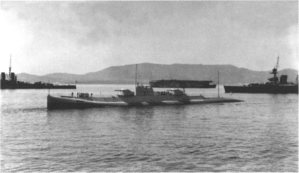
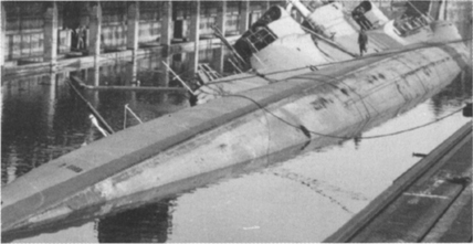
In drydock in 1931.
Asdic
Asdic5 had been invented in the latter stages of the Great War as a replacement for the extempore hydrophone installations, which were then the only means of detecting a submerged submarine. It became widely fitted to surface ships of the Royal Navy, and it was erroneously believed to have rendered the submarine impotent.6
In his memo, A W Johns proposed that the question of whether or not to fit Asdic in X.1 should wait on future trials with H.32. She had been built by Vickers at Barrow-on-Furness and commissioned on 27 May 1919.7 In 1921 design work began on a submarine Asdic, based on the set first fitted to a ‘P’ Boat, but inverted. Designated the Type 113, it first went to sea in H.32 the following year. The quartz transducer was fitted inside a retracting canvas-covered dome, which required a period of immersion before it became sound-transparent. This troublesome canvas dome was soon replaced by a copper one. Initial results were obviously promising, for on 12 May 1923 approval was given to fit an Asdic installation in X.1 She would be the first submarine to be designed as such to have an Asdic compartment installed. As at 26 January 1925, H.32 and X.1 were the only submarines so far fitted with Asdic. Four L.50 class subs were to be fitted with Asdic while building. The special set fitted to X.1 was designated the Type 113X, and was strengthened for deep diving. It was also provided with a hinged cover to protect the oscillator dome from gun blast. In 1930 X.1’s set had its electronics updated, when it was redesignated the Type 113C.
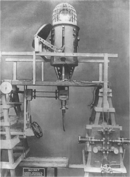
The Asdic Type 113X turret ready to be installed in X.1, in a mock-up showing the control wheels and the hinged turret cover. The framework covering the oscillator was to be fitted with a canvas cover as on H.32, but in practice it was replaced with a thin copper dome. This item was extremely fragile and when removed for maintenance required careful handling.
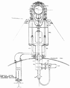
The Asdic turret raised on hydraulic rams into the operating position, Oscillator vertical, facing forward.
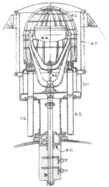
The Asdic turret retracted for surface action, with its hinged cover in place, Oscillator horizontal, with the original design of frame for a canvas cover.
Asdic brought many advantages. Since X.1 was of a size to present a tempting target to smaller, submerged boats, her Asdic set was designed to detect other submarines as well as surface targets. The set also had an important navigational function in X.1, as befitted her role as a corsair submarine in the wide blue yonder. Vast areas of the sea had been surveyed by surface ships, but depths and rocks had only been investigated down to about 70ft. X.1’s Asdic set enabled her to detect and avoid uncharted rocks when she was proceeding submerged.8
OSCILLATOR, MK.III D. 2 PLY.
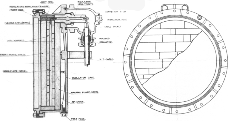
A drawing of the 2-Ply quartz oscillator of the Asdic Type 113X.
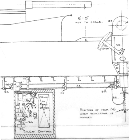
The Asdic arrangements showing the silent compartment, with its double wheel (37) for training and elevating the oscillator, the pair of headphones (17) for the operator and an officer, the Morse key (21), the operating rods for the Asdic turret (53), and the repeater rod to the control room (46). Also shown in side view is the hinged cover which protects the Asdic turret from the blast of ‘A’ turret’s guns close overhead.
The original intentions were that Asdic was to be used for navigational and target ranging, and also for communications. It offered the possibility of coordinating divisional attacks by several boats at once. Trials were carried out with H.32 between June 1925 and January 1926, and the reports were copied to Lt-Commander Phillips in X.1 as to:
• station-keeping with another non-Asdic equipped submarine;
• attacking without periscope exposed after an initial periscope sighting had been made;
• avoiding anti-submarine attacks by surface escorts;
• transmitting of messages between surface vessels and submerged submarines;
• firing torpedo spreads on Asdic bearings.
Excellent results were achieved, and the Asdic set in H.32 was used to complement the underwater directional hydrophone receiver.
It was found that submarine Asdic was less affected by surface disturbances. High speed, which disrupted surface Asdic, was not a problem for a submerged submarine owing to the very low speeds achieved prior to the later stages of the Second World War.9
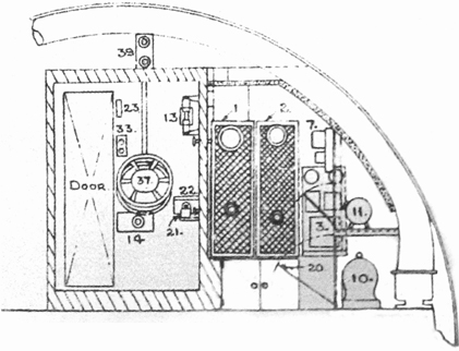
A section looking aft through the sound-insulated silent compartment on the left, where the operator sat, and the Asdic office to the right, containing the electrical equipment.
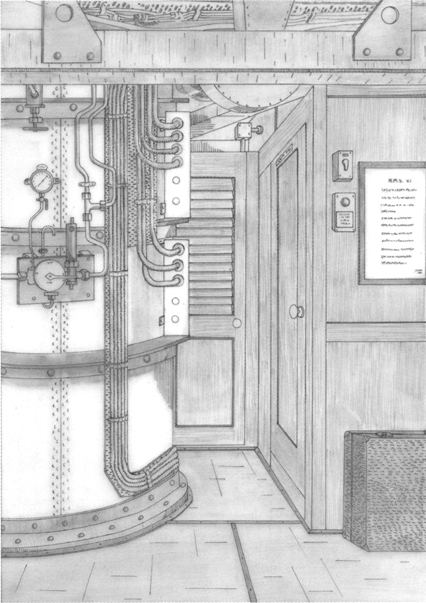
David Hill’s drawing of A’ turret trunking with, on the right, the door to the Asdic silent compartment.
Asdic pulses could be transmitted and received on a range of frequencies. This ability could be used to differentiate between attacking A/S vessels, and also to actively range on A/S vessels not transmitting if their search frequency was known, the submarine transmitting pulses on a different band to avoid the chance of the surface sets homing onto the submarine. The major problem with keeping an extended Asdic watch was the monotony of the operation, which resulted in extreme operator fatigue, and necessitated frequent reliefs. Obviously, a large submarine such as X.1 could carry a sufficient number of operators to mitigate this factor.
Unfortunately, despite the pioneering work done by H.32 and X.1, Royal Navy submariners would not use their Asdic for torpedo attacks, avoiding emitting active signals and using their Asdic set as a passive hydrophone receiver. The results achieved in all the above trials foreshadowed the much later work of the USN and RN nuclear hunter-killer submarines.
Hydrophones
In the same memo on communications, designer A W Johns ordered the installation of frame coils and revolving directional hydrophones (RDH). The retractable RDH instrument was installed as far forward as possible, in the bow just behind the Bull Ring (the steel ring on top of the bow used for mooring the ship).
Despite some notable successes during the Great War, hydrophones had proved to have limited applications for surface vessels in detecting and tracking submerged submarines in the open sea – especially when the target submarines were running near-silent or stopped on the bottom. Conversely, submerged submarines continued to make good use of hydrophones for detecting and identifying surface vessels. Experienced operators could differentiate between slow-turning mercantile screws and the faster high-pitched noise generated by a warship. They could provide accurate target bearings, an estimation of speed based on screw revolutions and the type of target, and some indication of range. Hydrophones could also warn of approaching torpedo screws, and the ‘click’ made by depth charge detonators as they were activated by hydrostatic pressure could prepare the crew for the resultant explosion. Hydrophones were of course the principal means of picking up submerged transmissions sent out by the Fessenden Gear, the underwater equivalent of the later ‘talk between ships’ (TBS) surface sets.
Fessenden Gear
Johns also instructed that Fessenden Gear would be fitted to X.1. In 1912 the Submarine Signal Company, which had specialised in signalling the position of lighthouses, lightships, shoals, wrecks and other hazards by means of underwater bells and the associated on-board reception devices, decided to go into competition with Marconi’s aerial wireless transmission system. They hired electrical engineer Professor R A Fessenden to develop an underwater Morse Code transmitter. During the Great War the Fessenden Gear allowed submerged boats to communicate at ranges of between 30 and 40 miles. On 21 April 1922 A W Johns proposed to incorporate a submerged transmissions (S/T) cabinet which would be used for sending and receiving submerged transmissions. Situated beneath the control room, adjacent to the wireless room, it was set up as a second ‘silent cabinet’ for the hydrophone operator. The apparatus to be installed in X.1 was tested at Chatham on 27 July 1922.
Submarine sounding machine
On 10 March 1922 a submarine sounding machine was ordered from Kelvin Bottomley & Baird Ltd of Glasgow. The depth of water beneath the ship could be calculated by leading overboard a cable attached to a sinker. The cable would be carried clear of the hull on a boom. As the sinker descended, the cable would pay out until, on it reaching bottom, the cable would slacken. At that point the seamen manning the machine would read off the figure on the dial at the top which gave the length of wire paid out, in fathoms. They would then refer to a table to ascertain the true depth, taking into account the angle of descent of the sinker at any given speed of the ship.
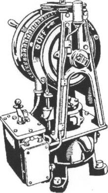
A ‘Kelvite’ sounding machine of the period.
Wireless telegraphy
For surfaced wireless transmissions, Johns proposed WT masts suitable for a reliable day range of 1,000 miles. The masts themselves were ordered on 6 April 1922, and would be of the retractable (telescopic) type to reduce underwater resistance. Both were of three-throw design, the forward mast extending from a well set in the front of the conning tower to a height of 35ft 9in and being capped with a T-piece aerial spreader; the rear mast with a similar spreader retracted into the rear hull and was of necessity longer, extending to 43ft 3in. When the masts were extended, the 150ft long three-wire aerial was carried at a height of 68ft above the surface, and ended in a special WT cabinet measuring 13ft by 6ft. As installed, it was intended that the WT set should transmit with a 100 per cent success rate at a range of 500 miles, and that at 1,000 miles, 80 per cent of messages transmitted should be successful. Given the power of shore-based radio communications equipment, reception could normally be assured even at maximum range.
Underwater position indication equipment
On 3 April 1926 the Signal Department memoed that a grenade signal ejector was to be fitted. This device permitted a submerged submarine to indicate its position – for example during exercises – by firing a ‘water shot’ which would be visible on the surface.
Visual signalling
The after periscope standard at the rear of the conning tower carried a signal mast with a halliard on which signal flags could be hoisted. Behind this was fixed a watertight all-round flashing lamp. The sketch top right shows a potential use of this for flashing Morse Code signals, for daylight concentration manoeuvres. At ‘the sharp end’, the crew would fasten the jackstaff to fly the Union Flag. This fitting carried a light for use when at anchor, and was topped by the traditional brass dolphin, the famous symbol of the Submarine Service.
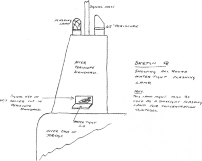
The after periscope standard on X.1, and the proposed modification on S/M X.2.
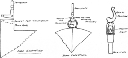
The jackstaff fitting.
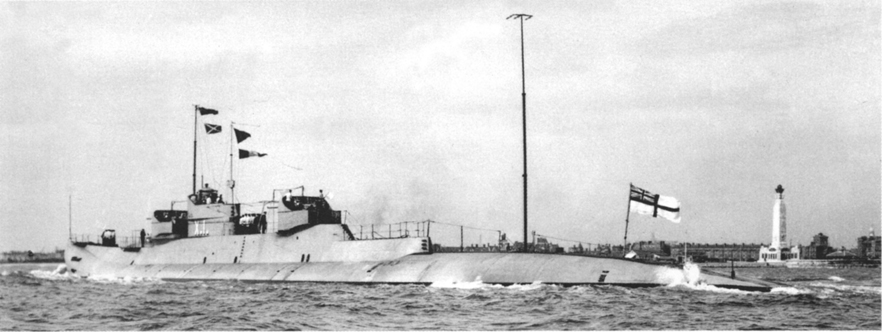
A view of X.1 probably off Portsmouth in September or October 1925 for torpedo trials, showing the WT masts extended.
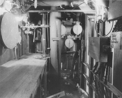
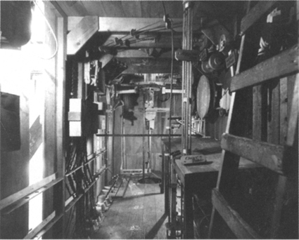
Mock-up of X.1’s upper control room, looking aft.
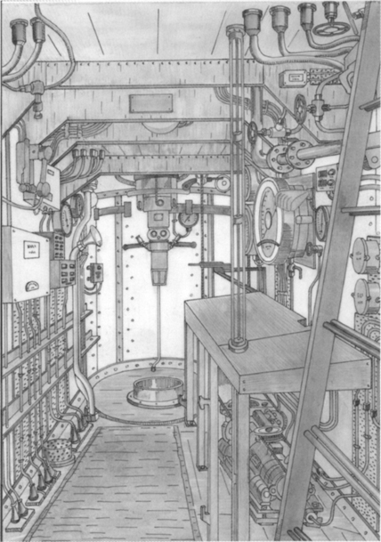
A drawing by David Hill of the same area as finally constructed, showing the 30ft periscope, and the chart table to the right. The ladder in the foreground connected with the conning tower and the DCT.
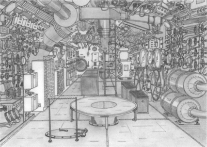
A drawing by David Hill, showing the main control room looking aft. In the centre, the raised platform is used when viewing through the forward 36ft periscope. The steam-driven ‘K’ class submarines also shared this feature. The circular hatchway in the foreground leads down into the CO2 machinery space below the control room, a space also occupied by the wireless office and the silent compartment for the hydrophone operator. On the left are valves controlling the main ballast tank vents and further aft on the same side the gyro compass relay panels and an electrical switchboard. The ladder amidships connects with the upper control room and behind the ladder are the gyro compass and a chart table. To the right are coolers for the air-conditioning system, behind which are the hydroplane control wheels, and in the aft corner one of the centrifugal ballast pumps.
Control Facilities
Unlike even the largest U-boats of the Great War, where the commanding officer stood alone in a ‘kiosk’ during attacks, RN submarine commanders directed operations from the control room under the conning tower, surrounded by the officers and ratings of the control team. Given the size and complexity of X.1, her control spaces were larger than normal, but still appeared extremely crowded. No internal photographs of X.1 have survived (if any were ever taken), but we can gain an impression of the upper control room from the photographs of the wooden mock-up prepared at Chatham Dockyard. This was used to work out the positions of all the various controls, gauges and communication devices, whilst still leaving sufficient space for the operators to carry out their functions.
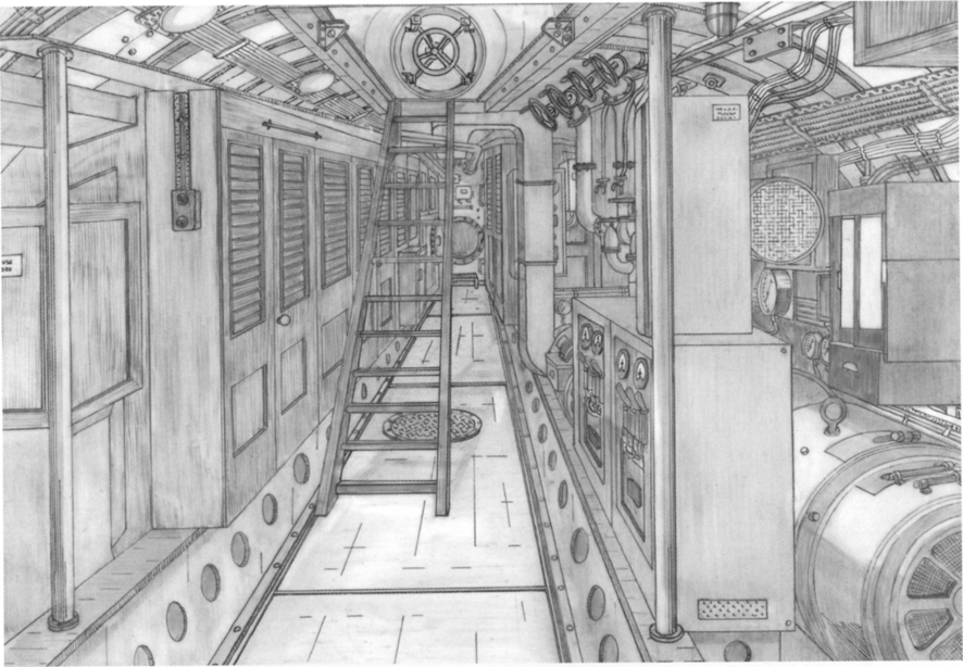
A David Hill drawing showing the pump room, looking aft. The wooden ladder led down from the foredeck. Whilst at sea this ladder would have been swung upwards and fixed to the deckhead to give more room in the narrow passageway. The watertight door leading aft into the wardroom can be seen at the end of the passageway. To the left in this view is a wooden fuse box and to the right the controls for the forward low-pressure blower.
As befitted an experimental vessel, X.1’s Kingston valves – which controlled her ballast tanks for diving and surfacing – had 20in diameter handwheels made of a ‘new aluminium alloy’, being 2 per cent nickel/3½ per cent copper/1 per cent magnesium/93½ per cent aluminium.
Periscopes
On 23 March 1922 the periscope specifications were fixed as
| Lookout | 42ft × 8½ins | (18½ft unsupported) |
| After (unifocal) (sic) | 36ft ×7½ins | (14½ft unsupported) |
| Forward (bifocal) | 36ft × 7½ins | (20ft unsupported at the upper control room or 14½ft unsupported at the lower control room) |
Barr & Stroud would provide the actual instruments. Blueprint No. 5727 in the Ship’s Cover at Greenwich shows the bottom end of Submarine Periscope Type CH9. This measured 42ft from window to eyepiece centre (monocular type).
The binocular power (B/P) scale was 1/2.
On 9 May 1922 Messrs Mechans Limited, of Scotetown Iron Works, Glasgow, produced the following quotations to supply the periscope shafting:
Three-throw types.
35 foot 9 inches, made of copper tube with gunmetal fittings and copper rope would cost £139-15-0;
43 foot 3 inches height above top of fixed tube, made of steel tube with gunmetal fittings and steel rope would cost £279-15-0;
- both quotes to include delivery.
Steering gear
The helm indicators were to be copied from those examined in surrendered German submarines. A W Johns proposed in a memo dated 19 August 1921 to use AC electrical gear, as on German U-boats. Cannibalised German AC gear was actually fitted in K.26. U 135 had been used by the Royal Navy for trials, and it was proposed to copy the AC gear tested in this U-Boat.10 The steering gear itself was to be supplied by Brown Brothers Rosebank Iron Works, Edinburgh, as per the order dated 7 April 1922. Brown Brothers’ price appears in an invoice dated 2 May 1922, in the amount of £1,880.
Forbes log
A Forbes log was installed in a tank just above the keel aft of frame 79. The ship’s speed was given by an impellor which revolved inside a tube, driven by the flow of water past the hull.
Boats
As befitted a vessel costing as much as a light cruiser, and carrying a far larger crew than any previous RN submarine, X.1 was outfitted with a suitable set of small boats:
• Two 16ft skiff drop keel dinghies, fitted with 5–6bhp petrol motors;
• One 13ft 6in dinghy.
These boats were stowed inboard, under cover, in the superstructure in front of ‘Y’ turret, and were hoisted in and out by a folding derrick.
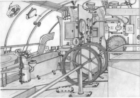
A David Hill drawing of the aftermost compartment, looking forward towards the No 10 watertight bulkhead. This compartment contained the emergency steering position, showing the wheels as rigged for emergency use. Under normal operating conditions they would have been stored elsewhere to allow access to the electric cooking range shown on the right. On the port side is a washing area containing two sinks, a bath and a slop ejector for disposing of food waste. Reportedly the bath was rarely if ever used as such.
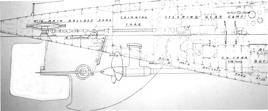
The steering gear compartment and X.1’s substantial rudder.
Complement
As per the original specifications, the crew was to comprise:
7 Petty Officers
16 Stokers
1 Rangetaker
1 Leading Director Layer
2 Gun Layers 2nd class
61 Ratings
plus 7 Executive Officers (including 2 Captains of Turrets)
plus 2 Engine Room Officers
Grand Total 97
On 23 November 1926 the final crew total was minuted as 109 officers and men (including an additional 12 ratings).
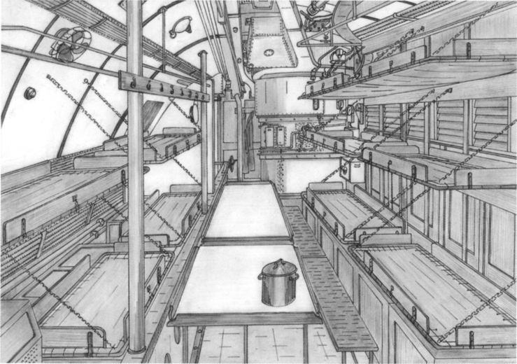
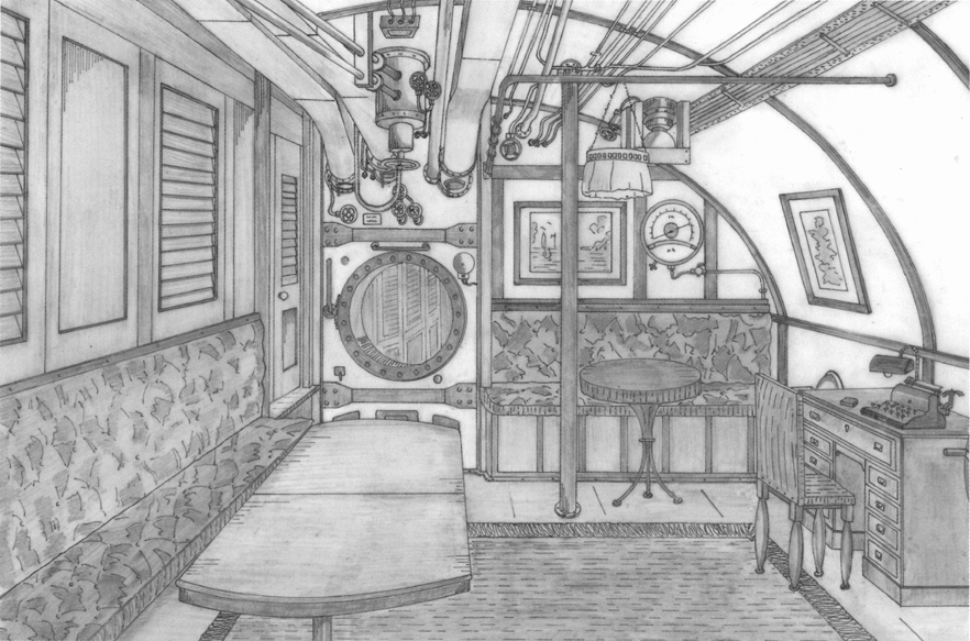
David Hill’s drawing of the petty officers’ mess looking forward. Ten folding bunks were fitted in this compartment, which was reported to be very cramped when in use. An electric urn was fitted at the after end of the compartment.
Given her experimental rôle, and the highly temperamental nature of her complex propulsion machinery, X.1’s complement was to include one Engineering Commander and one Engineering Lieutenant. Normally only depot ships had an Engineering Commander. All other submarines had an Engineering Lieutenant only. Lt W H Bigwood joined her Engineering staff in 1925, and his letters have provided much insight into working conditions on board.
Habitability
In his comments for the projected X.2, Lt-Commander Ruck-Keene wrote in October 1928 that the worst congestion was in the Petty Officers’ Mess. The Engine Room Artificers’ Mess was very cramped and ‘the bathing arrangements are atrocious’. As the engine room staff suffered more than most on board X.1 it is likely they were the most vociferous in their complaining!
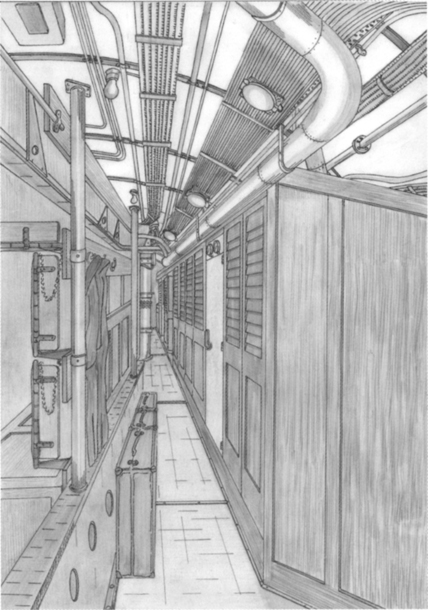
David Hill’s drawing of the accommodation passageway looking forward to ‘A’ turret trunking. To the left, two steel pillars add strength to the compartment when X.1 went deep.
The officers also suffered, as their wardroom was used as a thoroughfare between the control room and the fore ends while at sea. One of several steel support pillars was sited somewhat inconveniently in the centre of the passageway. Meals were taken at an extending table to port, behind which were two small cabins. More happily, a small Spirits Room was adjacent, forward to port. The majority of the crew slept in hammocks.
Cooking facilities were extensive, and situated throughout the ship. Three upper deck galleys were located in the highest point of the superstructure, between the gun turrets, and in addition there were four electric cooking ranges installed inside the pressure hull. Frozen meat came from the main cold store.
To give some degree of shade from the Mediterranean sun, the crew could rig awnings. As befitted such a large vessel, her arrangements for hanging these were quite sophisticated. The sketch below was included in the file of papers proposing the stillborn X.2, and gives the overall appearance of the awnings. Note that for X.2 it was proposed to double up the ridge ropes, and not rely on a single backbone rope as on X.1.
Commanding Officers
| 1 December 1922 | Cdr Robert H T Raikes DSO* |
| 28 January 1925 | Cdr Philip E Phillips DSO* |
| 28 July 1927 | Cdr C H Allen DSO |
| 29 July 1930 | Cdr E C M Baraclough |
| 9 February 1931 | Lt Cdr A L Besant |
| 30 December 1931 | Cdr J N MacNair |
| 1 March 1933 | Cdr J D A Musters DSC |
| 8 December 1933 | Lt Cdr C B Barry DSO |
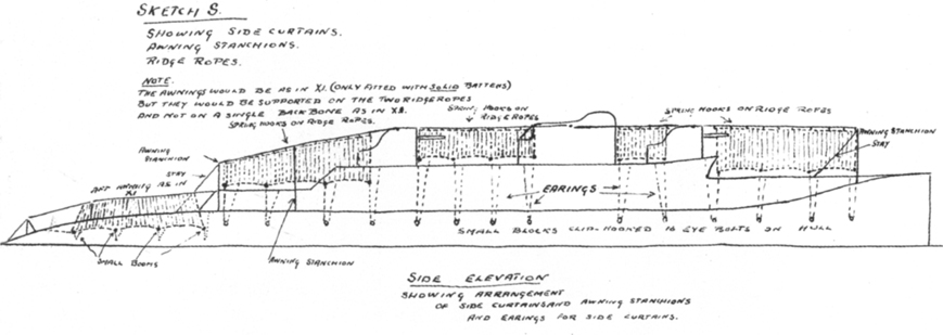
Sketch of the awnings rigged at anchor in hot climes.
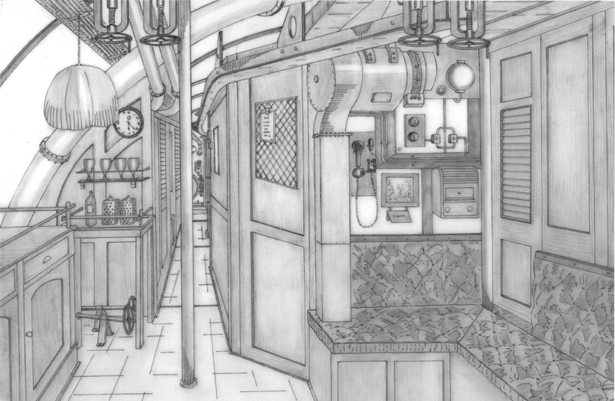
looking aft
