Wall studs taller than 10 ft. require No. 2 or better grade construction lumber. Shorter walls may be built with cheaper No. 3 grade in most cases.
1. Use Number 3, standard, or stud grade wood for most load-bearing walls not more than 10 feet tall. Do not use this wood for load-bearing walls more than 10 feet tall. Use Number 2 grade or better lumber for walls more than 10 feet tall.
2. You may use utility grade wood for nonload-bearing walls.
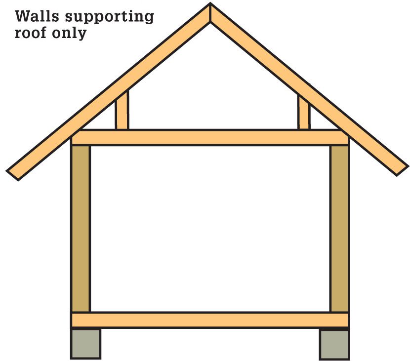
3. You may use utility grade wood for load-bearing exterior walls that support only a ceiling and a roof if the studs are spaced not more than 16 inches on center and the walls are not more than eight feet tall.
4. Refer to general codes for more information about other wall height and stud spacing combinations.
5. Refer to general codes for wall height and stud spacing requirements in high wind, heavy snow load, and seismic design areas.
1. Use the table below to determine stud size and spacing when the unsupported vertical height of an exterior load-bearing wall is not more than 10 feet. Measure vertical height between points of horizontal (lateral) support between studs. Vertical wall height is usually measured between the bottom of the sole or sill plate and the bottom of the floor or ceiling. Consult a qualified engineer before measuring unsupported vertical wall height between points other than at floor levels.
Wall studs taller than 10 ft. require No. 2 or better grade construction lumber. Shorter walls may be built with cheaper No. 3 grade in most cases.
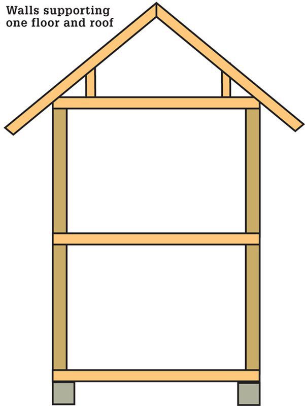
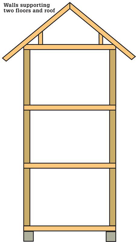
Stud Size & Spacing for Load-bearing Walls 
Stud size (inches) |
Maximum stud spacing supporting only one floor, or supporting a ceiling and roof with or without a habitable attic |
Maximum stud spacing supporting one floor and a ceiling and roof with or without a habitable attic |
Maximum stud spacing supporting two floors and a ceiling and roof with or without a habitable attic |
2 × 4 |
24" |
16" |
Not allowed |
2 × 6 |
24" |
24" |
16" |
1. Use the adjacent table to determine stud size and spacing for nonload-bearing walls. Measure vertical height between points of horizontal (lateral) support between studs. Vertical wall height is usually measured between the bottom of the sole or sill plate and the bottom of the floor or ceiling. Consult a qualified engineer before measuring unsupported vertical wall height between points other than at floor levels.
Stud Size & Spacing for Nonload-bearing Walls
Stud size |
Maximum stud height |
Maximum stud spacing |
2 × 4 |
14 ft. |
24" |
2 × 6 |
20 ft. |
24" |
1. Use at least two 2-inch (nominal) depth top plates that are at least as wide as the studs at the top of load-bearing walls. Example: use two 2 × 4 top plates on top of a 2 × 4 wall and use 2 × 6 top plates on top of 2 × 6 walls.
2. Offset joints where two pieces of top plate meet by at least 24 inches. You do not need to place a stud under a joint in a top plate unless the stud would be placed there for other reasons.
3. Lap one top plate from one wall over the top plate of an intersecting wall at the wall corners and at the intersection with load-bearing walls.
4. You may use a single top plate at the top of nonload-bearing walls.
5. You may use a single top plate on load-bearing walls if wall joints and corners and top plate end joints are secured with at least a 3-inch by 6-inch by 0.036-inch thick galvanized steel plate secured by at least six 8d nails on each side of the connection; and if the supported framing above (such as joists or rafters) is not more than one inch from the stud below. This exception is not commonly used.
6. Install one galvanized metal strap at least 0.054-inch thick and 1 1/2 inches wide on a top plate if it is cut more than 50 percent of its actual depth. These metal straps are sometimes called FHA straps. It is not necessary to install a strap on both top plates for purposes of this section. You may need to install shield plate to protect plumbing pipes and electrical wires.
7. Extend the strap at least six inches beyond each side of the cut opening. Secure the strap with at least eight 16d nails on each side of the strap.
8. Apply this strap requirement to top plates in exterior and interior load-bearing walls.
9. You do not need to install the strap if wood structural panel sheathing covers the entire side of the wall with the notched or cut top plates.
10. Use at least one 2-inch (nominal) depth bottom plate that is at least as wide as the studs. Note that some jurisdictions allow treated plywood to serve as the bottom plate for curved walls. Verify this local exception with the building official.
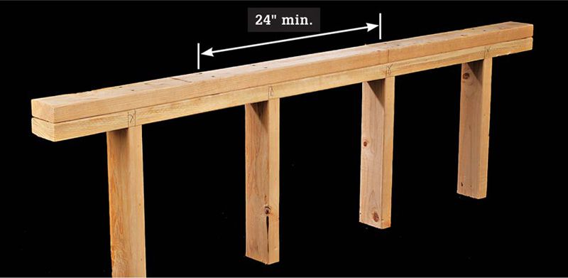
Offset joints where 2 top plates meet by at least 24".
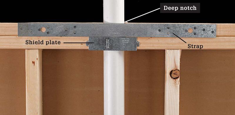
Install a strap across 1 top plate when it is notched more than half its width. Install another strap or a shield plate when required to protect pipes and electrical wires.
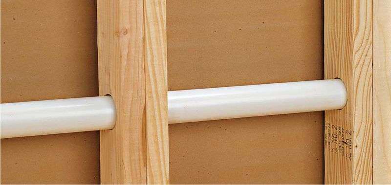
 NOTCHES & HOLES IN WALL STUDS
A bore is a hole drilled in a stud or joist. Use the actual dimensions to determine the depth of framing lumber and when calculating the maximum hole diameter.
A notch is a piece cut from the smaller dimension of framing lumber such as a stud or joist. Use the actual dimensions to determine the depth of framing lumber and when calculating the maximum notch depth. Actual dimensions are the dimensions of framing lumber after finishing at the mill. Example: the nominal dimensions of a 2 × 6 are 2 inches by 6 inches and the actual dimensions, after finishing, are about 1 1/2 inches by 51/2 inches.
1. Notch a load-bearing stud not more than 25 percent of its actual depth. Example: notch a 2 × 6 load-bearing stud not more than 13/8 inches.
2. Notch a nonload-bearing stud not more than 40 percent of its actual depth. Example: notch a 2 × 6 nonload-bearing stud not more than 21/4 inches.
1. Bore a hole in a single load-bearing stud not more than 40 percent of its actual depth. Example: bore a 2 × 6 load-bearing stud not more than 21/4 inches in diameter.
2. You may bore holes in load-bearing studs not more than 60 percent of their actual depth if you install a double stud and do not bore more than two successive studs.
3. Bore a hole in a nonload-bearing stud not more than 60 percent of its actual depth. Example: bore a 2 × 6 nonload-bearing stud not more than 31/4 inches in diameter.
4. Leave at least 5/8 inch of undisturbed wood between the hole and the stud edge.
5. Do not place a hole and a notch in the same horizontal section of the stud.
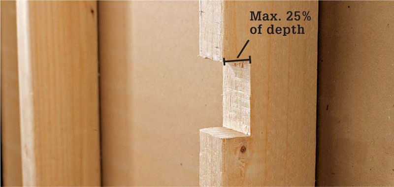
Notch a load-bearing stud not more than 25 percent of its actual depth.
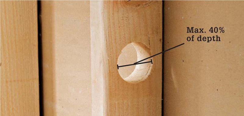
Drill a hole in a load-bearing stud not more than 40 percent of its actual depth.
Double two load-bearing studs if the holes are not more than 60 percent of their actual depth.
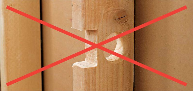
VIOLATION! Do not locate a notch and a hole in the same part of the stud.