WIRING
RECEPTACLES: REPLACING
A120-volt duplex receptacle can be wired to the electrical system in a number of ways. The most common are shown on these pages.
Wiring configurations may vary slightly from these photographs, depending on the kind of receptacles used, the type of cable, or the technique of the electrician who installed the wiring. To make dependable repairs or replacements, use masking tape and label each wire according to its location on the terminals of the existing receptacle.
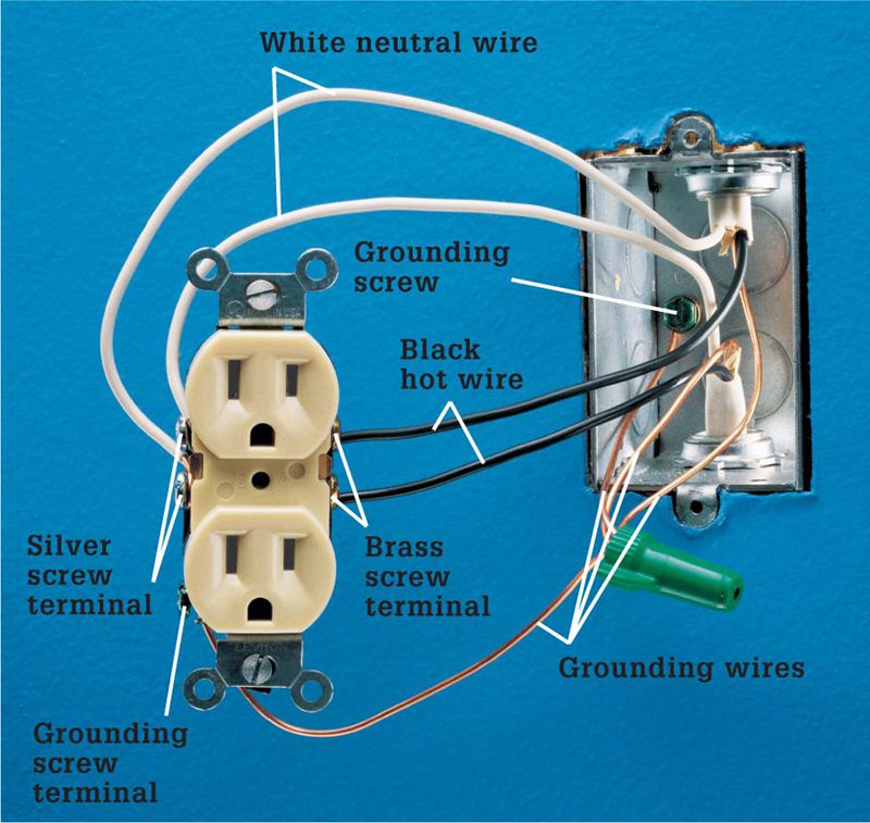
Receptacles are wired as either end-of-run or middle-of-run. These two basic configurations are easily identified by counting the number of cables entering the receptacle box. End-of-run wiring has only one cable, indicating that the circuit ends. Middle-of-run wiring has two cables, indicating that the circuit continues on to other receptacles, switches, or fixtures.
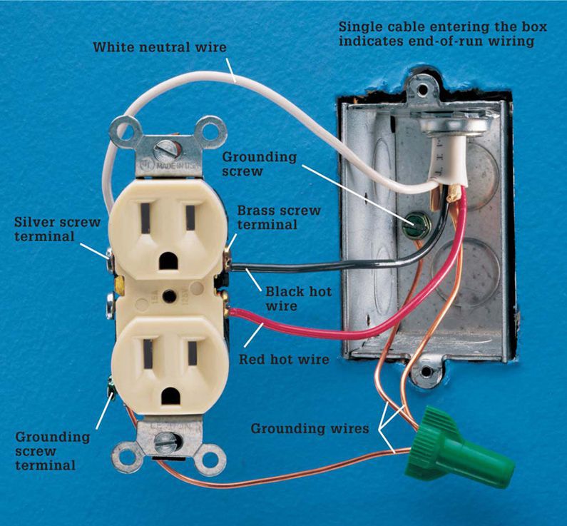
A split-circuit receptacle is shown on the next page. Each half of a split-circuit receptacle is wired to a separate circuit. This allows two appliances of high wattage to be plugged into the same receptacle without blowing a fuse or tripping a breaker. This wiring configuration is similar to a receptacle that is controlled by a wall switch. Code requires a switch-controlled receptacle in any room that does not have a built-in light fixture operated by a wall switch.
Split-circuit and switch-controlled receptacles are connected to two hot wires, so use caution during repairs or replacements. Make sure the connecting tab between the hot screw terminals is removed.
Two-slot receptacles are common in older homes. There is no grounding wire attached to the receptacle, but the box may be grounded with armored cable or conduit. Tamper-resistant receptacles are now required in all new residential installations.
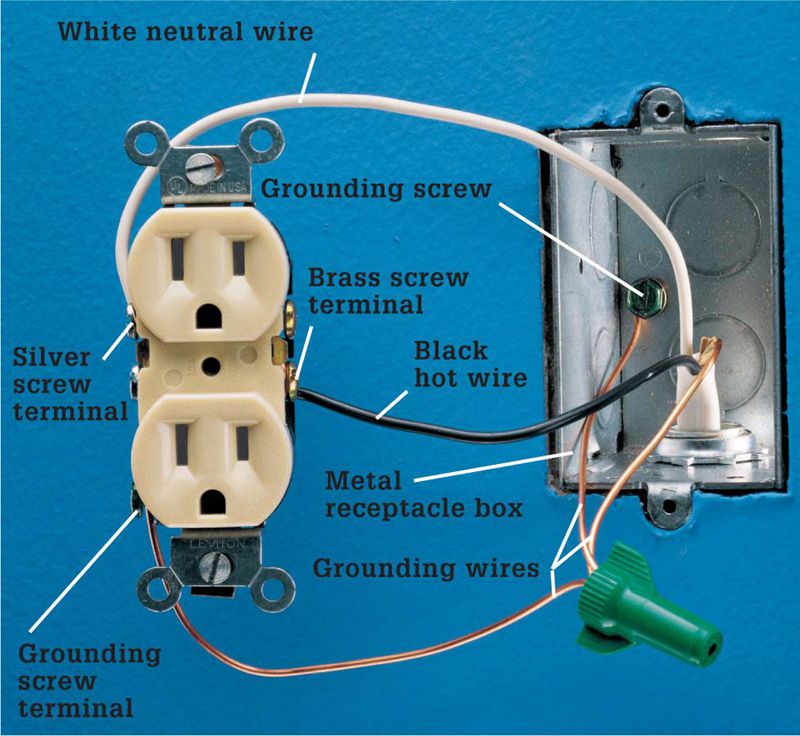
Single cable entering the box indicates end-of-run wiring. The black hot wire is attached to a brass screw terminal, and the white neutral wire is connected to a silver screw terminal. If the box is metal, the grounding wire is pigtailed to the grounding screws of the receptacle and the box. In a plastic box, the grounding wire is attached directly to the grounding screw terminal of the receptacle.
Two cables entering the box indicate middle-of-run wiring. Black hot wires are connected to brass screw terminals, and white neutral wires to silver screw terminals. The grounding wire is pigtailed to the grounding screws of the receptacle and the box.
A split-circuit receptacle is attached to a black hot wire, a red hot wire, a white neutral wire, and a bare grounding wire. The wiring is similar to a switch-controlled receptacle. The hot wires are attached to the brass screw terminals, and the connecting tab or fin between the brass terminals is removed. The white wire is attached to a silver screw terminal, and the connecting tab on the neutral side remains intact. The grounding wire is pigtailed to the grounding screw terminal of the receptacle and to the grounding screw attached to the box.
A two-slot receptacle is often found in older homes. The black hot wires are connected to the brass screw terminals, and the white neutral wires are pigtailed to a silver screw terminal. Two-slot receptacles may be replaced with three-slot types, but only if a means of grounding exists at the receptacle box. In some municipalities, you may replace a two-slot receptacle with a GFCI receptacle as long as the receptacle has a sticker that reads “No equipment ground.”


