
Wall switches are available in three general types. To repair or replace a switch, it is important to identify its type.
Single-pole switches are used to control a set of lights from one location. Three-way switches are used to control a set of lights from two different locations and are always installed in pairs. Four-way switches are used in combination with a pair of three-way switches to control a set of lights from three or more locations.
Identify switch types by counting the screw terminals. Single-pole switches have two screw terminals, three-way switches have three screw terminals, and four-way switches have four. Most switches include a grounding screw terminal, which is identified by its green color.
When replacing a switch, choose a new switch that has the same number of screw terminals as the old one. The location of the screws on the switch body varies depending on the manufacturer, but these differences will not affect the switch operation.
Whenever possible, connect switches using the screw terminals rather than push-in fittings. Some specialty switches have wire leads instead of screw terminals. They are connected to circuit wires with wire connectors.

A wall switch is connected to circuit wires with screw terminals or with push-in fittings on the back of the switch. A switch may have a stamped strip gauge that indicates how much insulation must be stripped from the circuit wires to make the connections.
The switch body is attached to a metal mounting strap that allows it to be mounted in an electrical box. Several rating stamps are found on the strap and on the back of the switch. The abbreviation UL or UND. LAB. INC. LIST means that the switch meets the safety standards of the Underwriters Laboratories. Switches also are stamped with maximum voltage and amperage ratings. Standard wall switches are rated 15A or 125V. Voltage ratings of 110, 120, and 125 are considered to be identical for purposes of identification.
For standard wall switch installations, choose a switch that has a wire gauge rating of #12 or #14. For wire systems with solid-core copper wiring, use only switches marked COPPER or CU. For aluminum wiring, use only switches marked CO/ALR. Switches marked AL/CU can no longer be used with aluminum wiring, according to the National Electrical Code.
 SINGLE-POLE WALL SWITCHES
A single-pole switch is the most common type of wall switch. It has ON-OFF markings on the switch lever and is used to control a set of lights, an appliance, or a receptacle from a single location. A single-pole switch has two screw terminals and a grounding screw. When installing a single-pole switch, check to make sure the ON marking shows when the switch lever is in the up position.
In a correctly wired single-pole switch, a hot circuit wire is attached to each screw terminal. However, the color and number of wires inside the switch box will vary, depending on the location of the switch along the electrical circuit.
If two cables enter the box, then the switch lies in the middle of the circuit. In this installation, both of the hot wires attached to the switch are black.
If only one cable enters the box, then the switch lies at the end of the circuit. In this installation (sometimes called a switch loop), one of the hot wires is black, but the other hot wire usually is white. A white hot wire should be coded with black tape or paint.
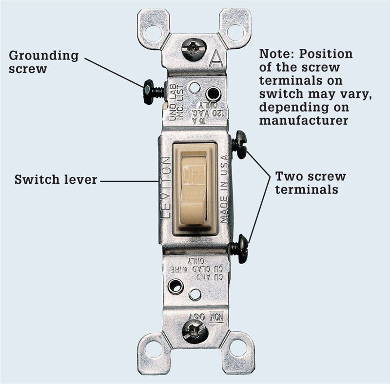
A single-pole switch is essentially an interruption in the black power supply wire that is opened or closed with the toggle. Single-pole switches are the simplest of all home wiring switches.
 TYPICAL SINGLE-POLE SWITCH INSTALLATIONS
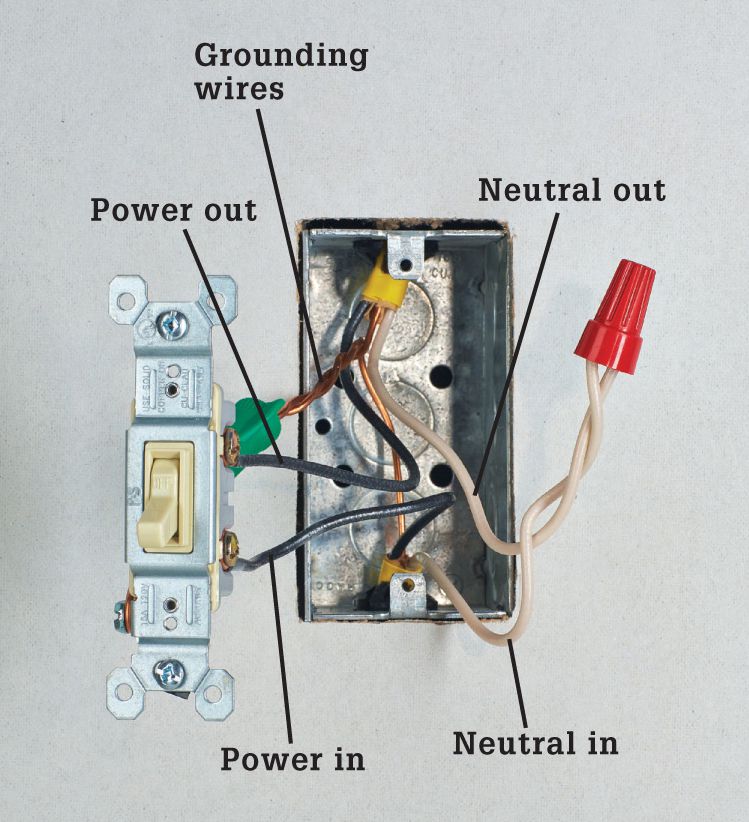
Two cables enter the box when a switch is located in the middle of a circuit. Each cable has a white and a black insulated wire, plus a bare copper grounding wire. The black wires are hot and are connected to the screw terminals on the switch. The white wires are neutral and are joined together with a wire connector. Grounding wires are pigtailed to the switch.
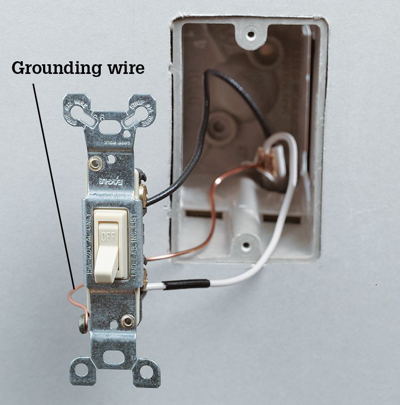
One cable enters the box when a switch is located at the end of a circuit. The cable has a white and a black insulated wire, plus a bare copper grounding wire. In this installation, both of the insulated wires are hot. The white wire should be labeled with black tape or paint to identify it as a hot wire. The grounding wire is connected to the switch grounding screw.
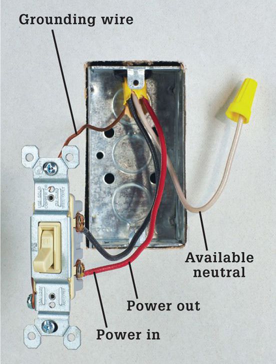
Code change: In new switch the white wire should not supply current to the switched device and a separate neutral wire should be available in the switch box.
 THREE-WAY WALL SWITCHES
Three-way switches have three screw terminals and do not have ON-OFF markings. Three-way switches are always installed in pairs and are used to control a set of lights from two locations.
One of the screw terminals on a three-way switch is darker than the others. This screw is the common screw terminal. The position of the common screw terminal on the switch body may vary, depending on the manufacturer. Before disconnecting a three-way switch, always label the wire that is connected to the common screw terminal. It must be reconnected to the common screw terminal on the new switch.
The two lighter-colored screw terminals on a three-way switch are called the traveler screw terminals. The traveler terminals are inter change able, so there is no need to label the wires attached to them.
Because three-way switches are installed in pairs, it sometimes is difficult to determine which of the switches is causing a problem. The switch that receives greater use is more likely to fail, but you may need to inspect both switches to find the source of the problem.
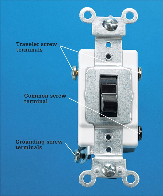
 TYPICAL THREE-WAY SWITCH INSTALLATIONS
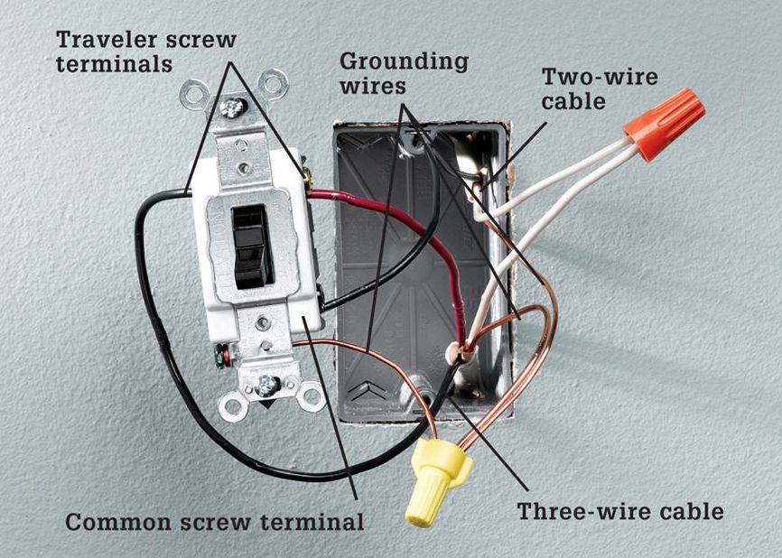
Two cables enter the box if the switch lies in the middle of a circuit. One cable has two wires, plus a bare copper grounding wire; the other cable has three wires, plus a ground. The black wire from the two-wire cable is connected to the dark common screw terminal. The red and black wires from the three-wire cable are connected to the traveler screw terminals. The white neutral wires are joined together with a wire connector, and the grounding wires are pigtailed to the grounded metal box.
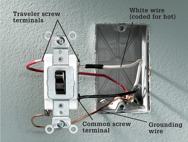
One cable enters the box if the switch lies at the end of the circuit. The cable has a black wire, red wire, and white wire, plus a bare copper grounding wire. The black wire must be connected to the common screw terminal, which is darker than the other two screw terminals. The white and red wires are connected to the two traveler screw terminals. The white wire is taped to indicate that it is hot. The bare copper grounding wire is connected to the grounded metal box.