WALLS & CEILINGS
VENT FAN: INSTALLING
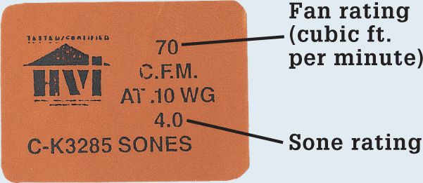
Most vent fans are installed in the center of the bathroom ceiling or over the toilet area. A fan installed over the tub or shower area must be GFCI protected and rated for use in wet areas. You can usually wire a fan that just has a light fixture into a main bathroom electrical circuit, but units with built-in heat lamps or blowers require separate circuits.
If the fan you choose doesn’t come with a mounting kit, purchase one separately. A mounting kit should include a vent hose (duct), a vent tailpiece, and an exterior vent cover.
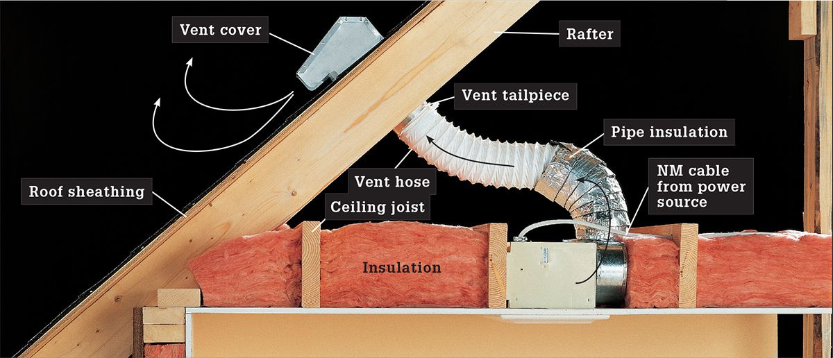
The most common venting options are attic venting and soffit venting. Attic venting routes fan ductwork into the attic and out through the roof. Always insulate ducting in this application to keep condensation from forming and running down into the motor. And carefully install flashing around the outside vent cover to prevent roof leaks.
Soffit venting involves routing the duct to a soffit (roof overhang) instead of through the roof. Check with the vent manufacturer for instructions for soffit venting.
To prevent moisture damage, always terminate the vent outside your home—never into your attic or basement.
You can install a vent fan while the framing is exposed or as a retrofit, as shown in this project.
Bathroom vent fans must be exhausted to the outdoors, either through the roof or through a wall. Flexible ductwork is allowed for bath vent fans (but not for clothes dryers).
 HOW TO INSTALL A BATHROOM VENT FAN
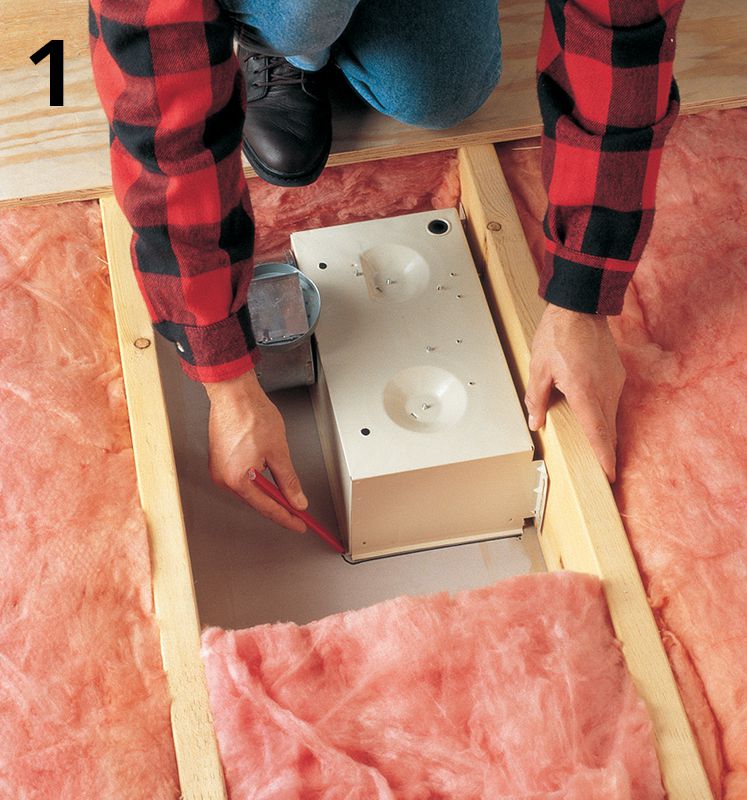
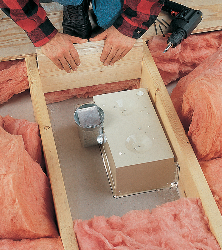
Position the vent fan unit against a ceiling joist. Outline the vent fan onto the ceiling surface. Remove the unit, then drill pilot holes at the corners of the outline and cut out the area with a jigsaw or drywall saw.
Remove the grille from the fan unit, then position the unit against the joist with the edge recessed 1/4" from the finished surface of the ceiling (so the grille can be flush mounted). Attach the unit to the joist using drywall screws.
Variation: For vent fans with heaters or light fixtures, some manufacturers recommend using 2× lumber to build dams between the ceiling joists to keep the insulation at least 6" away from the fan unit.
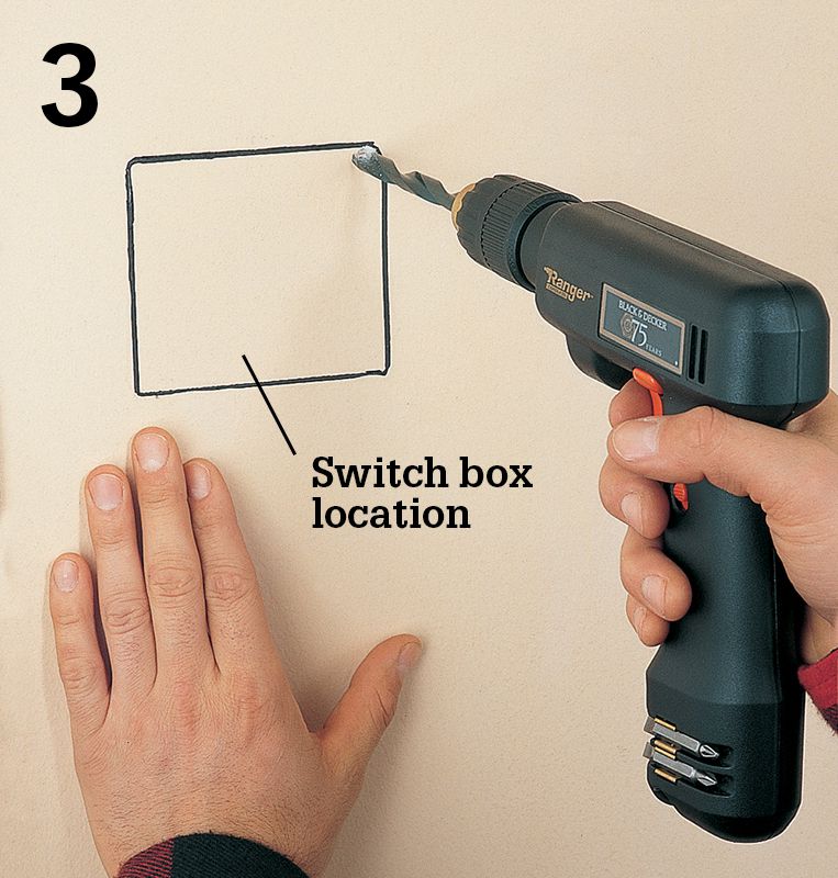
Mark and cut an opening for a double-gang box on the wall next to the latch side of the bathroom door, then run a 1 4/3 NM cable from the switch cutout to the fan unit. Run a 1 4/2 NM cable from the power source to the cutout.
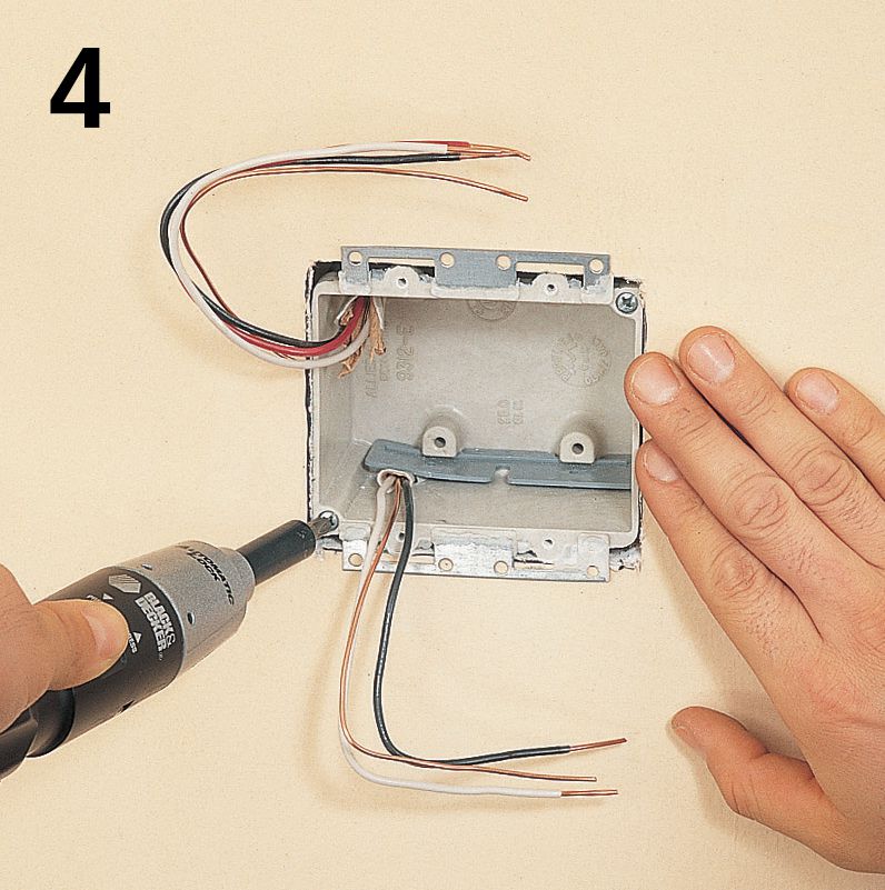
Strip 10" of sheathing from the ends of the cables, then feed the cables into a double-gang retrofit switch box so at least 1/2" of sheathing extends into the box. Clamp the cables in place. Tighten the mounting screws until the box is secure.
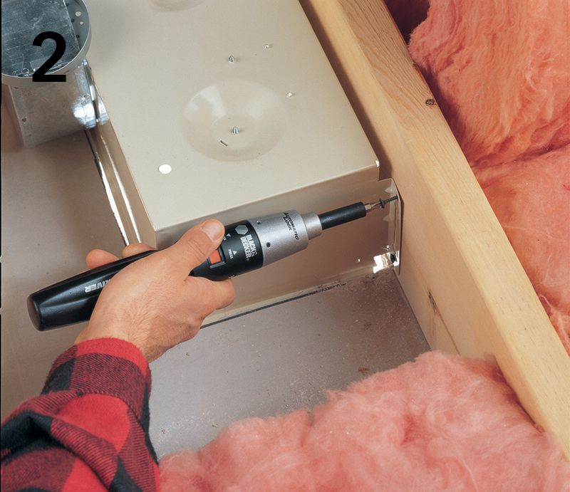
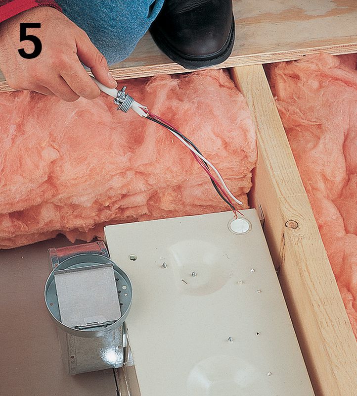
Strip 10" of sheathing from the end of the cable at the vent unit, then attach a cable clamp to the cable. Insert the cable into the fan unit. From the inside of the unit, screw a locknut onto the threaded end of the clamp.
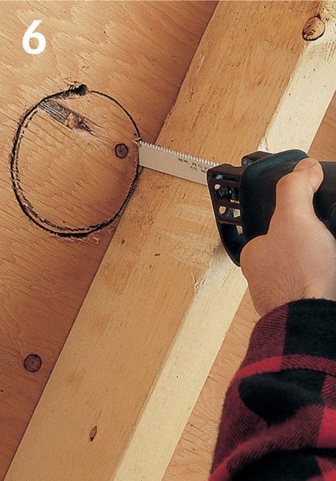
Mark the exit location in the roof next to a rafter for the vent duct. Drill a pilot hole, then saw through the sheathing and roofing material with a reciprocating saw to make the cutout for the exhaust tailpiece.
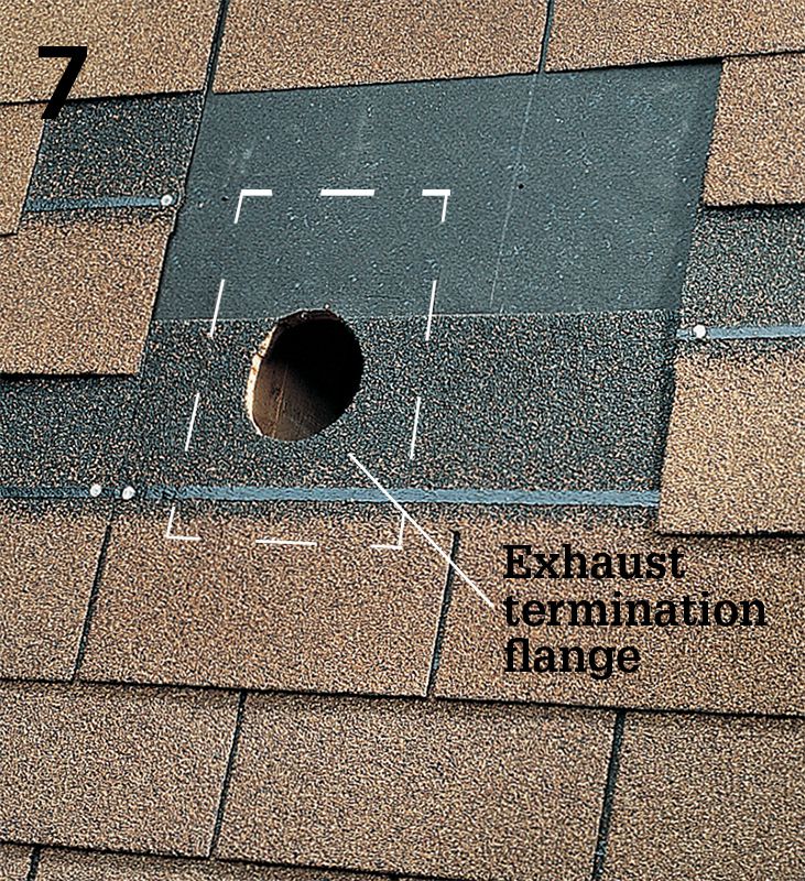
Remove a section of shingles from around the cutout, leaving the roofing paper intact. Remove enough shingles to create an exposed area that is at least the size of the exhaust termination flange.
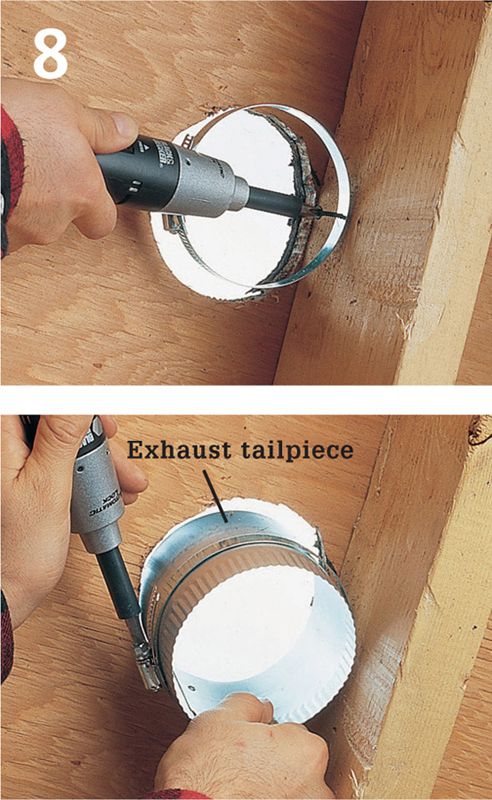
Attach a hose clamp to the rafter next to the roof cutout about 1" below the roof sheathing (top). Insert the exhaust tailpiece into the cutout and through the hose clamp, then tighten the clamp screw (bottom).
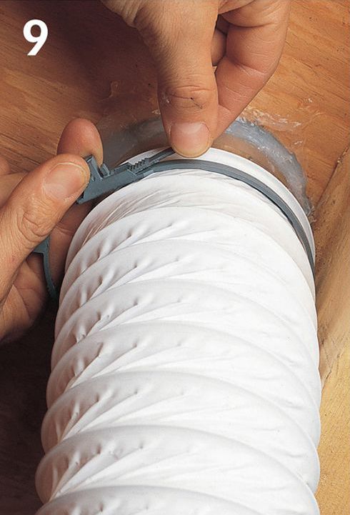
Slide one end of the exhaust duct over the tailpiece, and slide the other end over the outlet on the fan unit. Slip hose clamps or straps around each end of the duct, and tighten the clamps.
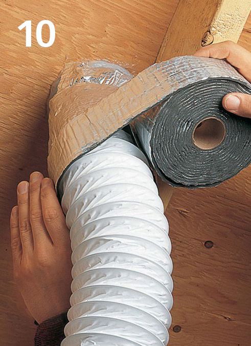
Wrap the exhaust duct with pipe insulation. Insulation prevents moist air inside the hose from condensing and dripping down into the fan motor.
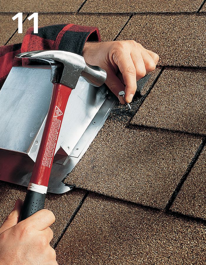
Apply roofing cement to the bottom of the exhaust termination flange, then slide the termination over the tailpiece. Nail the termination flange in place with self-sealing roofing nails, then patch in shingles around the cover.
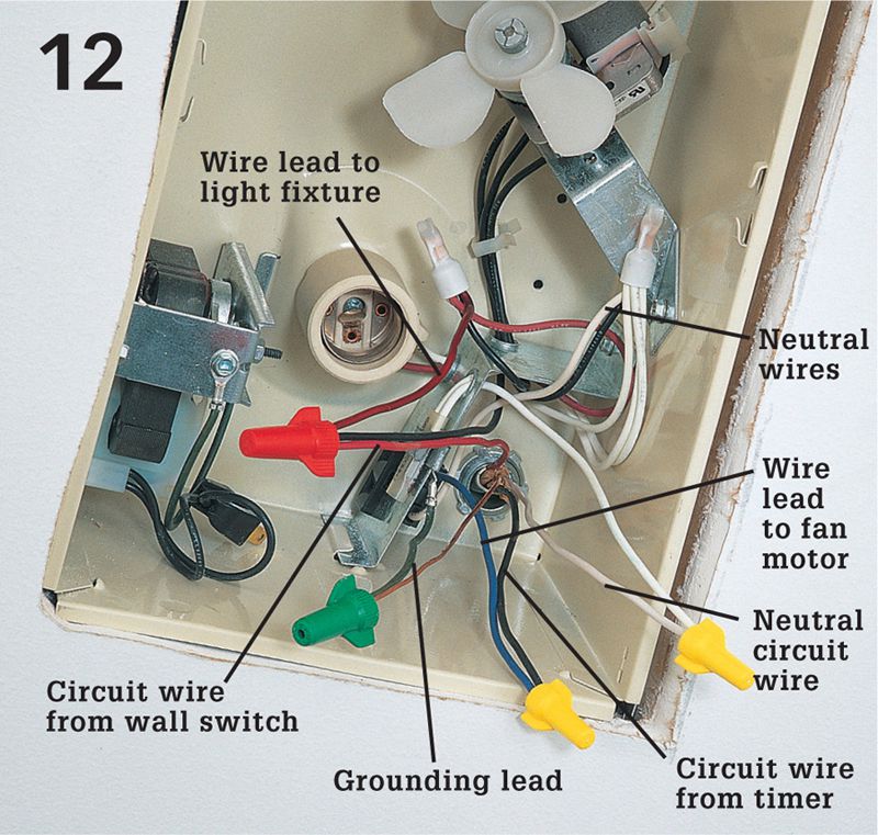
Ensure power is off and test for power. Make the following wire connections at the fan unit: the black circuit wire from the timer to the wire lead for the fan motor; the red circuit wire from the single-pole switch (see step 14) to the wire lead for the light fixture in the unit; the white neutral circuit wire to the neutral wire lead; the circuit grounding wire to the grounding lead on the fan unit. Make all connections with wire connectors. Attach the cover plate over the unit when the wiring is completed.
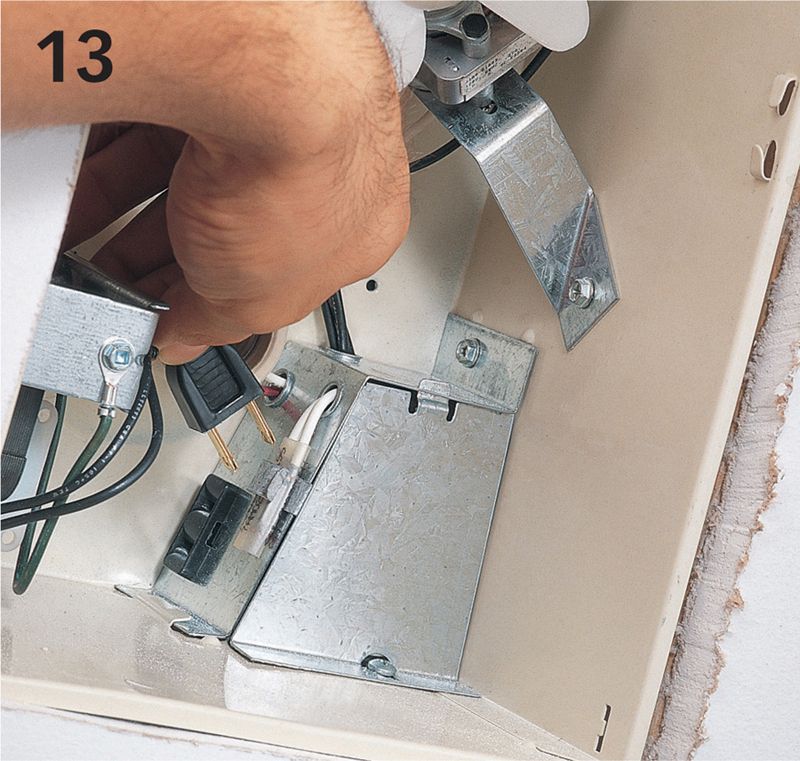
Connect the fan motor plug to the built-in receptacle on the wire connection box, and attach the fan grille to the frame using the mounting clips included with the fan kit. Note: If you removed the wall and ceiling surfaces for the installation, install new surfaces before completing this step.
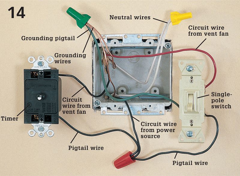
Ensure power is off and test for power. At the switch box, add black pigtail wires to one screw terminal on the timer and to one screw terminal on the single-pole switch; add a green grounding pigtail to the groundling screw on the switch. Make the following wire connections: the black circuit wire from the power source to the black pigtail wires; the black circuit wire from the vent fan to the remaining screw on the timer; the red circuit wire from the vent fan to the remaining screw on the switch. Join the white wires with a wire connector. Join the grounding wires with a green wire connector.
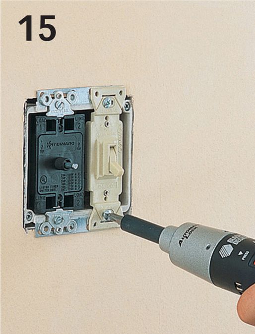
Tuck the wires into the switch box, then attach the switch and timer to the box. Attach the cover plate and timer dial. Turn on the power.