Chapter 1 – Amazon EC2 Basic
s
Regions, Availability Zones, Images, Accounts
As noted in the introduction, Amazon database services are managed, platform services (PaaS) built on cloud infrastructure services (IaaS) provided by Amazon EC2. Understanding EC2 concepts is a prerequisite for understanding Amazon database services.
The entire infrastructure comprising Amazon EC2 (i.e., computer facilities, hardware, network, storage, and software resources) is geographically distributed among an ever growing number of globally dispersed and independent locations called regions
. Basically, regions are established in separate geographic areas, typically in close proximity to major urban areas. Examples of names of Amazon EC2 regions contemporary to this publication include …
Each region is made up of clusters of data centers known as
availability zones.
Inquisitive and astute readers are encouraged to reference the
AWS Glossary
to confirm the definition of a region -- which emphasizes the practicality of including a minimum of two availability zones within a region, and that a region, in effect, is a logical name for grouping the collection of all AWS resources within its locale.
16
For availability zones, the
AWS Glossary
definition stresses that a region’s availability zones are separate but interconnected physical environments, and are shielded from each other’s local outages or infrastructure failures.
So, essentially, Amazon EC2 provides the ability to distribute cloud applications supported by virtual servers (aka virtual machines), network and data resources across multiple locations. Cloud application resources can be replicated across multiple regions for facilitating disaster recovery for an enterprise’s mission-critical applications. Availability zones are isolated, independent, highly-available data centers and are generally unperturbed by failures occurring in other availability zones. By launching virtual servers in separate availability zones, applications are protected from failures in a single location, thereby enabling high availability.
Virtual servers in Amazon EC2 are simply called
instances
. The prerequisite starting point for launching an EC2 instance is called an Amazon Machine Image (AMI). Again,
avid cloud students are invited to consult the
AWS Glossary
to corroborate the definition of an AMI, emphasizing that an AMI is a template (i.e., a master copy) the content of which is comparable to that of a server’s root drive. As such, an AMI establishes the operating system and other basic software components (e.g., app server, web server or database server software) minimally necessary for standing up an instance. An AMI’s content is encrypted and stored within AWS (e.g., using the Amazon Simple Storage Service --
Amazon S3
).
17
So, an AMI essentially is a “launch pad” for propelling an instance into the AWS cloud. From an AMI (e.g., an AMI for initiating a Linux/Apache web server), many instances can be spawned which can be thought of as clones of the AMI and functioning as EC2 virtual servers.
AMIs and instances are examples of EC2 resources
tied to an AWS account
. The registration process for a new AWS customer results in creation of an AWS account for billing usage of AWS resources.
Again, voracious readers are encouraged to peruse the
AWS Glossary
to confirm the definition of an account. An account establishes information about the account owner including payment details for consuming any billable resources. An AWS account is also granted appropriate authorization for accessing and acting on any resources under its control. AWS account resources can be established in many regions. An account can own many AMIs.
Data Modeling Tutorial … Basics
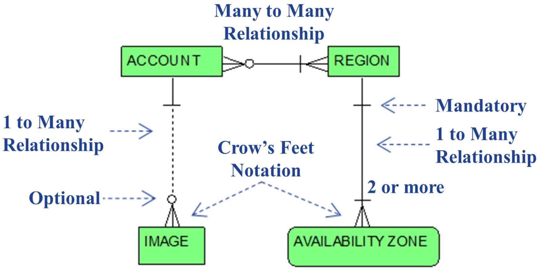
Figure 1.1 graphically summarizes the previous narrative by unveiling our initial entity-relationship diagram. As previously noted, all entity-relationship diagrams herein illustrate Information Engineering notation conventions as implemented by IDERA’s ER/Studio Data Architect. Figure 1.1 depicts fundamental entities and relationships for the EC2 concepts of region, availability zone, account, and image, and also facilitates a basic tutorial for introducing the aforementioned Information Engineering concepts and notation.
Figure 1.1 Regions, Availability Zones, Accounts, Image
s
The boxes in Figure1.1 represent entities. REGION, AVAILABILITY ZONE, IMAGE, and ACCOUNT are the names of entities for respectively maintaining information about regions, their associated availability zones, images accessible within a region, and accounts that own AWS resources, such as images. The REGION entity, for example, represents the set or collection of all regions within AWS. The AVAILABILITY ZONE entity represents the entire collection of all availability zones among all regions. The IMAGE entity represents the entire collection of all AMIs among all accounts. The ACCOUNT entity is the set of AWS accounts representing all AWS customers.
Solid or dashed lines connecting boxes represent relationships
between those entities. Two one-to-many
relationships and a single many-to-many
relationship are shown in Figure 1.1. Note the trident-like “Crow’s Feet Notation,” intuitively indicating the “many” end of these one-to-many relationships and both ends of the many-to-many relationship.
From this diagram’s graphical syntax, we can confidently infer that the one-to-many relationship between the REGION entity and the AVAILABILITY ZONE entity means that each region (i.e., each occurrence or member of the REGION entity, for example the “us-east-1” region) is made up of one or more availability zones (i.e., one or more members of the AVAILABILITY ZONE entity). More precisely, this relationship is annotated conforming to the
AWS Glossary
region definition, emphasizing that each region is minimally made up of two or more availability zones. Enabling high availability within a region makes no sense without at least two availability zones in the region.
Note the preference to use the terms “occurrence” or “member” of an entity, rather than the more commonly used data modeling terminology of an “instance” of an entity. The term “instance” of an entity is intentionally avoided herein so as not to be confused with an Amazon EC2 “instance.”
Note also the short horizontal bar “-
” crossing the relationship line at both ends of this relationship (i.e., near the box for the REGION entity and near the crow’s feet for the AVAILABILITY ZONE entity). This denotes that the relationship is mandatory
with respect to both entities. That is, each availability zone must
be associated with one and only one region. In data modeling vernacular, the AVAILABILITY ZONE entity is referred to as a dependent entity
. This means that each member of the AVAILABILITY ZONE entity cannot exist on its own and must be bound to a single region (i.e., a single member of the REGION entity). In other words, an occurrence of the AVAILABILITY ZONE entity exists only if it is inextricably linked to a single occurrence of the REGION entity. The relationship, of course, is also mandatory at the other end. By definition, a region requires at least two availability zones.
From Figure 1.1, we also infer that the one-to-many relationship between the ACCOUNT entity and the IMAGE entity means that each account (i.e., each occurrence or member of the ACCOUNT entity) can be the owner of one or more images (i.e., one or more members of the IMAGE entity).
Note also the circle “o” (denoting zero) perched on top of the crow’s feet for this relationship. This symbolizes that the relationship is optional
with respect to the IMAGE entity. This allows us to further infer that each occurrence of the ACCOUNT entity does not necessarily have any IMAGE members associated with it. More precisely, each account has zero, one or many associated images. Semantically equivalent, each account
can have
(or may have)
one or more associated images, but might not have any images. When an account is initially created for a new user, there are no images associated with, i.e., owned by, the account. However, public images owned by other accounts can be selected within a newly created account.
Note also the short horizontal bar “-
” crossing the relationship line at the opposite end of this relationship (near the box for the ACCOUNT entity). This denotes that the relationship is mandatory
with respect to the ACCOUNT entity. That is, each image must
be associated with one and only one account, i.e., the account that owns the image. The IMAGE entity is also a dependent entity
, in that each occurrence of the IMAGE entity cannot exist on its own and must be bound to a single occurrence of the ACCOUNT entity. Each image exists only if it is joined to the hip of a single account.
In Figure 1.1, note the many-to-many relationship between the ACCOUNT entity and the REGION entity. This simply reflects that, when an account is established it is empowered to create and use EC2 resources in one or more regions and, clearly in the opposite direction, a region’s resources can be accessed by many customer accounts.
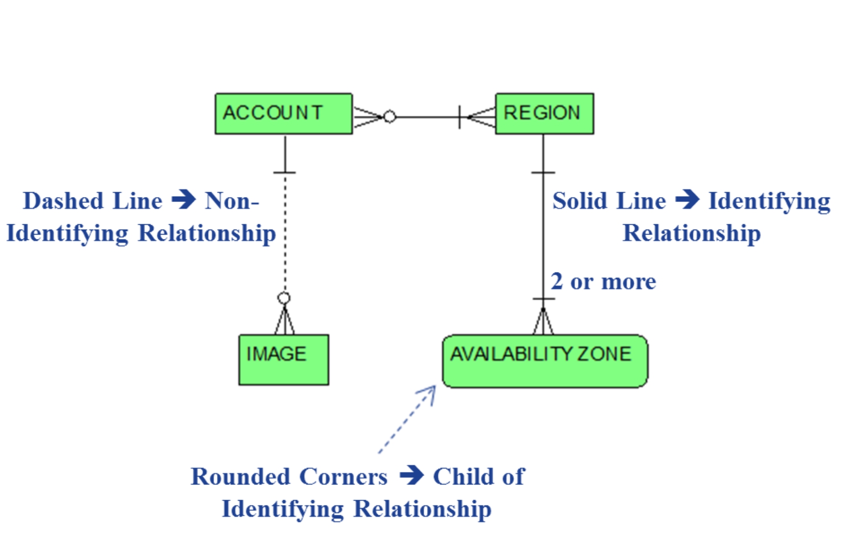
Note also the difference between the dashed line relationship between ACCOUNT and IMAGE entities and the solid line relationship between the REGION and AVAILABILITY as annotated in Figure 1.2.
Figure 1.2 Identifying vs. Non-Identifying Relationships
A solid line for a one-to-many relationship denotes an
identifying relationship
. A dashed line denotes a
non-identifying relationship
. To appropriately clarify this difference, it is necessary to introduce the concepts of
attributes
and
foreign keys
, both additional fundamental data modeling concepts. Again, the
DAMA-DMBOK
comes to the rescue by imparting practical, no-nonsense definitions.
11
First …. Attributes
…. Simply stated, each entity is labelled typically by several (and sometimes by many) attributes. Each attribute is given a name and identifies some property, characteristic or information detail, the values for which facilitate an un
derstanding of the entity. The values assigned to attributes are usually numbers, character strings, or dates. Typical examples of attributes in conventional information systems include last name, first name, date of birth, address, salary, marital status, gender,
and department
for example an EMPLOYEE entity.
Simple examples of attributes for the REGION entity are region code
and region name.
Values given to the region code
attribute (e.g., the character strings “us-east-1” and “us-west-1”) serve to uniquely identify each region, i.e., each member of the REGION entity.
The
DAMA-DMBOK
also divulges that there are two types of attributes:
key attributes or non-key attributes.
11
Simply stated, a key attribute either by itself or grouped with other key attributes serves the purpose of uniquely differentiating a member (i.e., an occurrence) of an entity from any other entity member. By itself, the
region code
attribute of the REGION entity is sufficient to establish uniqueness among all REGION members and, therefore, serves as a
key attribute
(aka
primary key
).
Note that values of the region name
attribute (e.g., “US East (N. Virginia)”) are also unique. Therefore, region name
could also be designated as a candidate key attribute. In such cases, one such attribute is designated as the key attribute, with remaining attributes relegated to the status of non-key attributes.
It is also often the case that multiple key attributes as a group are collectively needed for determining uniqueness and are thereby jointly referred to as the primary key.
Next ….
Foreign Keys
…. In this case, the
DAMA-DMBOK
again admirably serves as a useful informant.
11
The concepts of foreign keys and key attributes are tightly coupled. In simplest terms, a foreign key consists of one or more attributes of an entity and creates a linkage to a related entity. More specifically, a foreign key provides a unique pointer to a member of the related entity.
For example, in a one-to-many relationship, the primary key (i.e., one or more key attributes comprising the primary key) migrates to and arrives as a foreign key in the entity on the “many” end of the one-to-many relationship. Key attributes of the primary key are thereby replicated (perhaps with different attribute names reflecting different roles) in the related entity. In a nutshell, a foreign key is an attribute or a cluster of attributes whose values match primary key values in a related entity, thereby serving as a technique for joining
the related entities. A foreign key’s attributes can also participate in the primary key of the entity to which they migrated.
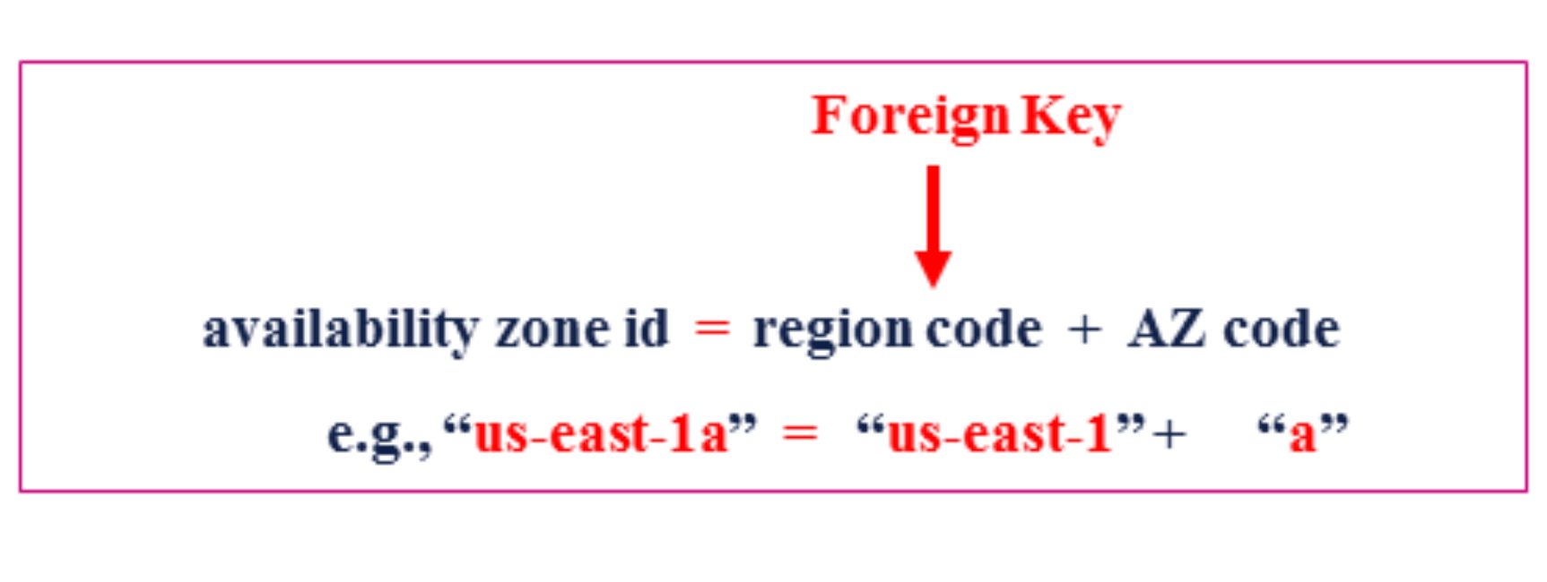
Applying the foregoing explanation to the one-to-many identifying relationship
between REGION and AVAILABILITY ZONE entities, the REGION entity’s key attribute (i.e., region code
) assists in identifying each occurrence within the AVAILABILITY ZONE entity. As actually implemented in EC2, the unique identifier for each availability zone consists of its associated region code
and suffixed by a single character, e.g., “a”, “b”, “c”, etc. For example, unique identifiers for availability zones within the “us-east-1” region (i.e., where region code = “us-east-1”) include:
-
us-east-1a
-
us-east-1b
-
us-east-1c
-
us-east-1d
-
us-east-1e
From the perspective of establishing a conceptual data model, however, an AZ code
attribute can be defined for the AVAILABILITY ZONE entity (i.e., similar to region code
for the REGION entity), whose values are single characters (as noted above “a”, “b”, “c”, etc.). This AZ code,
when concatenated as a suffix to the region code,
serves to uniquely identify availability zones within an associated region. So, each occurrence of the AVAILABILITY ZONE entity is uniquely identified by the combination of both the region code
and the AZ code
.
From the previous foreign key explanation, the region code
attribute of the REGION entity migrates to the AVAILABILITY ZONE entity as a foreign key
attribute. Thus, in this sense, the region code
attribute for REGION occurs in both entities, thereby joining both entities. The full identifier for each availability zone is the combination of the value held in the region code
attribute (i.e., the foreign key that migrated from the REGION entity) in combination with the value held in the AZ code
attribute of the AVAILABILITY ZONE entity.
Therefore, from the perspective of a conceptual data model, one can argue that the relationship between REGION and AVAILABILITY ZONE entities is an identifying relationship. In reality however (i.e., from the standpoint of a physical database design), these are inseparably combined into a single attribute which, in EC2 API documentation, is referred to as the availability zone id
. Nonetheless, region code
is an indelible component of an availability zone’s identity, illustrated as follows.
Note also the rounded corners for the depiction of the AVAILABILITY ZONE entity in both Figures 1.1 and 1.2. ER/Studio distinguishes dependent entities participating as the child entity of an identifying relationship (i.e., the entity at the “many” end of an identifying relationship) with rounded corners.
Conceptual data models … are used to understand the high level data entities for the domain in question … Conceptual models are not like your normal data model as they don’t contain much in the way of rigor. What we are after is the general feel for the key data entities and relationships. This model forms the framework we can use to undertake a more detailed analysis and design
.
To summarize, a conceptual data model’s purpose is to provide a high-level, visually intuitive description of potentially complex concepts and their relationships for the domain in question
, which of course in this case is Amazon EC2. As a result, the intent is not to provide exhaustive detail in terms of specifying all attributes belonging to each entity. Such is the objective of a more rigorous logical data model (LDM), which exploits the conceptual data model as its starting point. Attributes will be introduced only as necessary and appropriate, i.e., where it makes sense to enrich our understanding of Amazon EC2’s essential entities and relationships.
Instances and Instance Types
As introduced in the previous section, EC2 instances are simply virtual servers launched from AMIs. In the context of EC2, the term
instance
is really just a shortcut for
instance of a virtual server
. Once again, perspicacious readers are invited to consult the
AWS Glossary
to inspect the simplicity of the instance definition -- emphasizing that an
instance
is reproduced as a copy of an AMI and is spawned as a virtual server in the AWS cloud
.
A single image can be used to launch many instances. An instance cannot be created without referencing a single image. After an instance has been launched, its configuration of installed software components can be modified. For example, an instance launched from a basic LINUX image can then later be provisioned with Apache, thereby resulting in a web server instance. A new AMI can then be created from this modified instance.
When launching each instance, in addition to specifying an image, an
instance type
must also be specified indicating the sizes of the instance in terms of its number of virtual CPUs and the amount of memory and storage. The
AWS Glossary
further emphasizes that different instance types are intended for different purposes depending on the performance requirements of an application. Some instance types are more appropriate for standard applications characterized with low or moderate load requirements, whereas other more potent and higher-priced instance types are suitable for applications with high throughput or rapid response time requirements.
Each instance type offers different compute, memory and storage capacities. For example, names of “General Purpose” instance types include a1.medium, a1.large and a1.xlarge. Examples of “Compute Optimized” instance types include c5.large, c5.xlarge and c5.2xlarge. “Memory Optimized” instance types include r5.large, r5.xlarge and
r5.2xlarge.
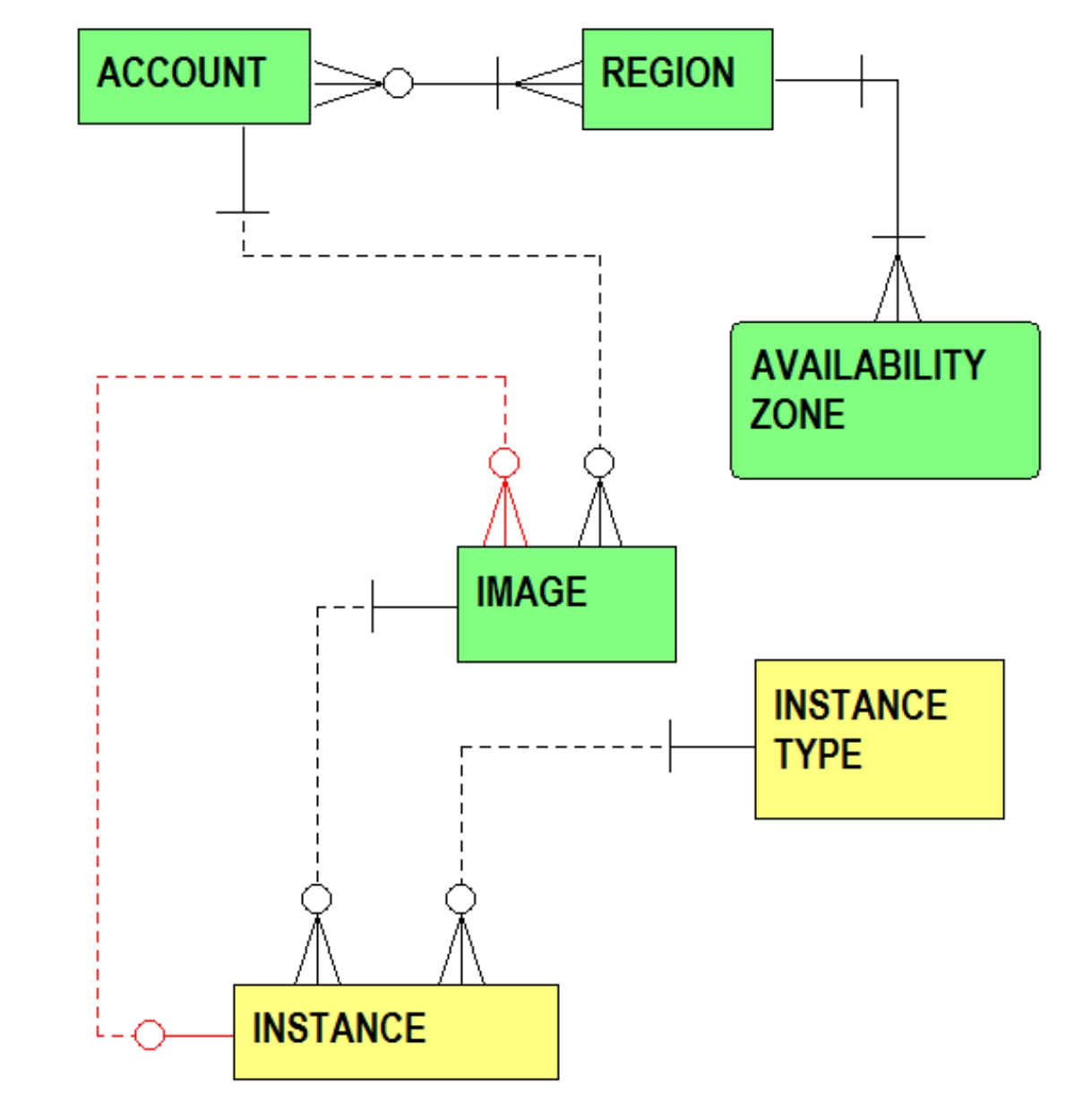
Figure 1.3 extends Figure 1.1 by including instance and instance type related entities and relationships.
Figure 1.3 Instances and Instance Types
From Figure 1.3, the one-to-many relationship from the INSTANCE TYPE entity to the INSTANCE entity reflects that each instance must be associated with a single instance type. Each instance type can apply to many instances. The one-to-many relationship from the IMAGE entity to the INSTANCE entity expresses that an instance must be generated, i.e., it must have been created, from a single image, and that an image can serve as the template for many instances. Note also the return-trip one-to-many relationship from the INSTANCE entity back above to the IMAGE entity. This emphasizes that an instance launched from an image can then be modified by installing additional software components. A new image can then be created from this modified instance. In the fullness of time, additional modifications are made to an instance, and it is possible that many different images can be spawned from the same instance.
VPCs, Subnets, IP Address Ranges, Security Groups
Amazon EC2 enables each account to establish one or more
Virtual Private Clouds
(VPCs). In simplest terms, a VPC is a virtual network functionally analogous to a conventional physical network typical of any corporate data center. Once again, unremitting and persevering cloud students might be motivated to consult the
AWS Glossary
to enjoy the simplicity of the VPC definition -- emphasizing flexibility of access by VPC resources to AWS services, shared connectivity and security facilities.
Essentially, a VPC is a network construct for segregating virtual servers and each VPC is logically separate from other VPCs in the AWS cloud. AWS resources such as EC2 instances, virtual firewalls, and other networking and security resources can be launched into a VPC. A range of IP addresses is apportioned to each VPC. Instances launched within a VPC are then provisioned with one or more IP addresses within this assigned IP address range
.
For example, a corporate enterprise can establish several VPCs for distinct reasons, such as for different organizations, product lines, profit centers, etc. Different VPCs can also be set up for various operational needs, such as establishing separate VPCs quarantining resources for applications development, quality assurance and production applications.
Each VPC can traverse more than one availability zone within the same region. Each VPC is composed of one or more subnets,
each with its own subset of IP addresses bounded within the same IP address range assigned to the VPC. Each subnet must be associated with a single VPC and a single availability zone. A second subnet within a VPC can be associated with a different availability zone. For high availability, a cloud application, therefore, can be established with instances in one subnet of a VPC and failover resources in a second subnet of the same VPC. But the second subnet is in a different availability zone.
The
subnet
definition from the
AWS Glossary
also emphasizes that an instance is assigned IP addresses within its subnet’s IP address range and that AWS resources can be launched and grouped into a selected subnet based on security requirements or operational needs.
Scenarios for establishing subnets satisfying special security and operational requirements include …
- Use of a public subnet
(aka a DMZ) for Internet facing resources, i.e., accessible from the Internet, such as load balancers or web servers responding to external requests from an enterprise’s customers.
- Use of a private subnet
for resources that are not directly accessible from the Internet, e.g., for web servers, application servers, and database servers that need to be accessed by resources launched within a public subnet.
- Use of a private subnet
for resources that are reserved for an enterprise’s internal applications.
- Subnets can also be established for segregating resources for applications development, QA, and production.
Figure 1.4 extends Figure 1.3 by including VPC and subnet related entities and relationships.
Figure 1.4 VPCs, Subnets, IP Address Range = CIDR Block, Security Groups
From Figure 1.4, the one-to-many relationship from the ACCOUNT entity to the VPC entity reflects that each VPC must be associated with a single account. In the other direction, each account can own many VPCs. The one-to-many relationships from the VPC and AVAILABILITY ZONE entities to the SUBNET entity expresses that each subnet must be tied to a single VPC and a single availability zone. In the opposite direction, an availability zone can host many subnets and a VPC can be composed of multiple subnets. The SUBNET entity, in effect, resolves an implicit many-to-many relationship between the AVAILABILITY ZONE entity and VPC entity. Accordingly, a VPC can traverse multiple availability zones, and each availability zone can host multiple VPCs, by virtue of the availability zone hosting VPC subnets. Note also the one-to-many relationship from the SUBNET entity to the INSTANCE entity. This emphasizes that each instance launched within a VPC must be tied to a single subnet. Each subnet can be associated with many instances.
Also in Figure 1.4, note the CIDR BLOCK entity. An IP address range is also known as a
CIDR block
.
19
A glimpse at the
AWS Glossary’s
CIDR block definition reveals that
CIDR
is an abbreviation for
Classless Inter-Domain Routing,
which is a structured method for allocating IP addresses and for facilitating the routing of IP packets between and within IP networks.
The one-to-many relationships from the CIDR BLOCK entity to the VPC and SUBNET entities express that each VPC must be tied to a single CIDR block and each subnet must also be associated with a single CIDR block. A subnet’s CIDR block is an IP address range which is a subset within the boundary of its parent VPC’s IP address range
.
The IP address ranges represented by these CIDR blocks consist of a series of private IP addresses, which are not publicly accessible via the Internet. These IP addresses are also private in the sense that they are reserved for enabling interaction between instances within the same VPC. These CIDR blocks are specified using what is known as Internet Protocol version 4 (IPv4) notation. It is possible to assign the same IPv4 CIDR block to multiple VPCs within the same account or among different accounts.
Also in Figure 1.4, note the SECURITY GROUP entity. Amazon EC2 is endowed with virtual firewalls referred to as
security groups
for governing and securing traffic to and from EC2 instances. Once again, astute readers are encouraged to seek guidance from
AWS Glossary’s
security group
definition. This definition draws attention to the many-to-many relationship between security groups and instances. More specifically, a security group can act as a firewall for many instances, and traffic for each instance can be regulated by more than one security group. At launch time, an instance can be coupled with one or more security groups. For each security group, firewall rules are specified for allowing inboun
d
traffi
c
or outboun
d
traffic, valid source and target IP address ranges, and permitted communication protocols (e.g., TCP, UDP, and ICMP). The one-to-many relationship between the VPC and SECURITY GROUP entities exhibits that each VPC can be associated with many security groups. The many-to-many relationship between the INSTANCE and SECURITY GROUP entities indicates that each instance must be fire-walled by at least one security group but possibly can belong to many security groups, and that each security group can govern traffic for many instances.
Instances … VPC vs. Classic
There are two general categories of EC2 instances:
classic instances
and
VPC instances
. At the dawn of AWS (i.e., for the initial releases of the AWS cloud) the AWS world was flat. The concept of VPCs had not yet arrived. The AWS cloud conceptually was a single level, horizontal network cloud that was common and shared by all AWS customers. VPCs were introduced to AWS late in 2013.
20
EC2 instances prior to the introduction of VPCs are known as classic instances. Legacy support is provided for classic instances of elderly AWS accounts that were created prior to the unveiling of VPCs. Newer accounts support only VPC instances, i.e., instances supported under the umbrella of a VPC.
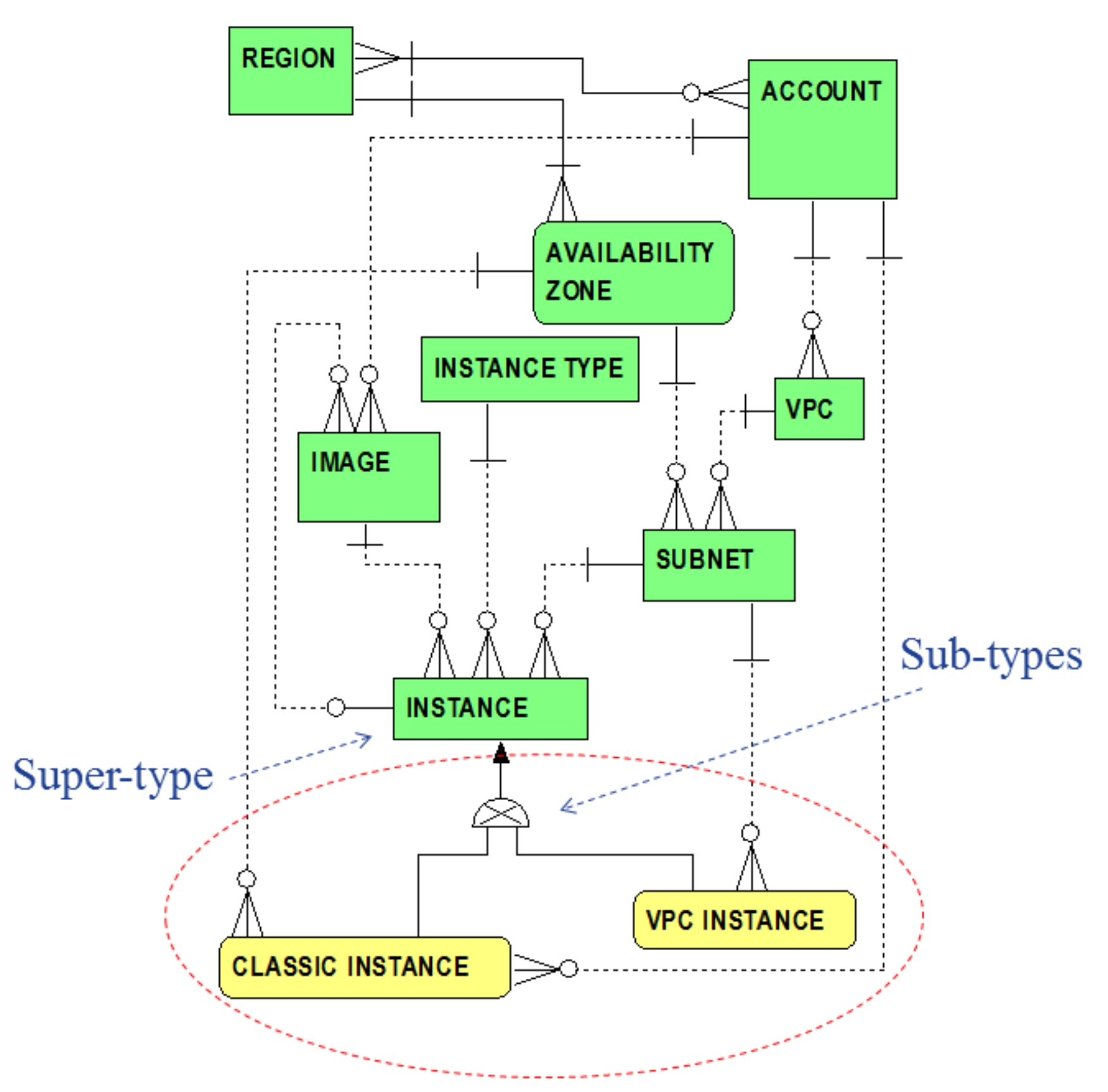
Classic instances, though still supported, are a remnant of antiquity, not available and disavowed for new AWS accounts. A classic instance is directly associated with its legacy account. Each VPC Instance is indirectly associated with its account via its subnet and VPC. Figure 1.5 extends Figure 1.4 by adding sub-types
for the INSTANCE entity.
Figure 1.5 Instance Sub-types: Classic vs. VPC Instances
From Figure 1.5, in data modeling vernacular, the INSTANCE entity is referred to as a super-type
of both the CLASSIC INSTANCE and VPC INSTANCE entities. CLASSIC INSTANCE and VPC INSTANCE entities are referred to as sub-types
of the INSTANCE super-type. In this case, the diagram (via the semi-circle with the embedded “X”) conveys that an instance must be either a classic instance or VPC instance; or, more precisely, a member of the INSTANCE entity must be either a member of the CLASSIC INSTANCE entity or a member of the VPC INSTANCE entity.
In many data modeling references, a description of super-types and sub-types is coupled with the concept of
generalization
. Again appropriating from the
DAMA-DMBOK
, one ascertains that a super-type is a generalization of its sub-types.
11
This means that a super-type is defined with attributes and relationships which are generic to (i.e., shared by) all of its sub-types. Each sub-type
inherits
such common attributes and relationships from its super-type but also differentiates itself with additional attributes or relationships peculiar to the sub-type. Each sub-type is in effect a special case of the super-type.
So the INSTANCE entity is a generalization of the CLASSIC INSTANCE and VPC INSTANCE entities. A CLASSIC INSTANCE is
a kind of
INSTANCE and a VPC
INSTANCE is
a kind of
INSTANCE. CLASSIC INSTANCE and VPC INSTANCE entities are special cases of the INSTANCE entity. An instance is exclusively either a classic instance or a VPC instance but not both. Note the italicized phrase “
a kind of
” is commonly used in data modeling literature to describe an inheritance relationship in the direction of a sub-type to its super-type (i.e., a sub-type is “
a kind of”
its super-type).
11
This phrase will continue to be italicized herein to subliminally emphasize such customary usage.
Rules and relationships are different depending on the sub-type. Classic instances are differentiated from VPC instances to show special relationships and rules relative to other Amazon EC2 concepts. In this case, Figure 1.5 differentiates the direct relationship from the CLASSIC INSTANCE sub-type to the ACCOUNT entity, the direct relationship from the VPC INSTANCE sub-type to the SUBNET entity, and allows one to infer an indirect relationship from the VPC INSTANCE sub-type to the ACCOUNT entity (via SUBNET and VPC entities).
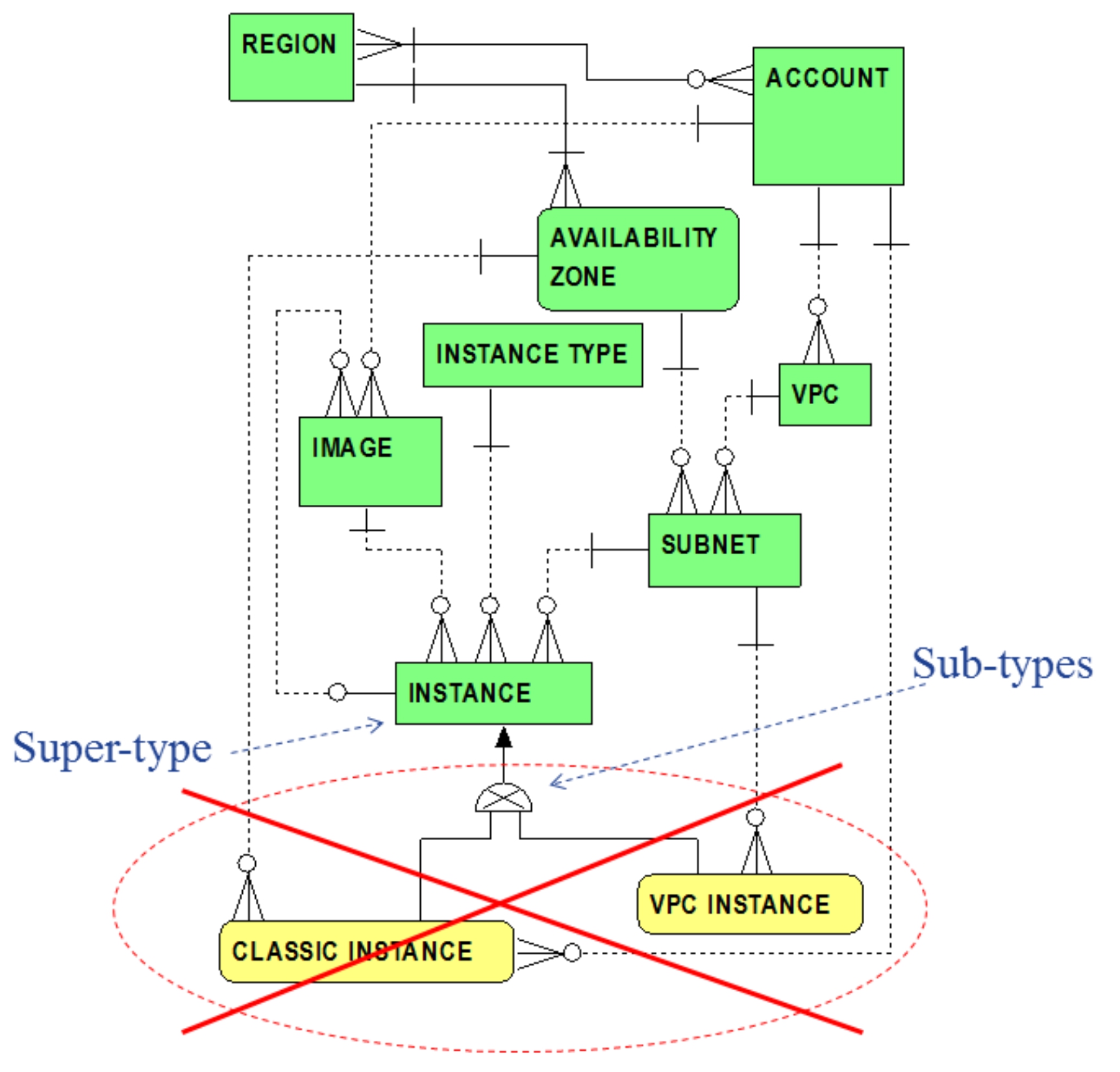
But again, it is worth emphasizing that classic instances can be considered an embryonic concept, grandfathered from the past, applying only to legacy AWS accounts. In the spirit of simplification, therefore, the conceptual data model evolving herein will adopt a viewpoint demoting classic instances from further consideration. Henceforth, it is assumed in this conceptual data model that all instances are VPC instances. The shunning of classic instances is illustrated as follows in Figure 1.6.
Figure 1.6 Classic Instances Not In Scop
e
Figure 1.6 highlights that classic instances are removed and exempted from the scope of this conceptual data model. Instances hereafter are declared to be VPC instances, thus substantially simplifying the data model. The INSTANCE entity reflects VPC instances only.
Resources, Tags
Amazon uses the term
resource
as a generalization for many of the basic EC2 concepts reflected as fundamental entities in the previously portrayed ERDs. Resource examples include VPCs, instances, images, security groups, and subnets. Essentially, a
resource
, as informally inferred from its
AWS Glossary
definition, is any AWS entity that a customer is able to act on, control or operate (e.g., by exercising the Amazon EC2 console, API, or CLI). A unique resource identifier -- referred to as an Amazon Resource Name or ARN -- is assigned to each resource when it is created.
Resources can also be anointed with user defined attributes known as
tags.
In basic terms, again inferring from its
AWS Glossary
definition, a tag is simply customer defined metadata, like a label attached to a resource. Tags can be declared to flexibly assign any additional customer-specific information, for example to further categorize or identify resources. Each tag consists of a key (i.e., a unique string of characters), and an optional value, which is also a string of characters.
Examples of resource tags might include an account number
and department
that will be billed for the resource, the owner
of the resource, a brief description of its purpose
, etc. The semantics of each tag is entirely within the customer’s purview and interpretation.
Figure 1.7 depicts essential entities supporting resources and tags.
 Figure 1.7 Resources and Tag
s
Figure 1.7 Resources and Tag
s
From Figure 1.7, The RESOURCE entity is shown as a super-type having many resource sub-types, each corresponding to previously introduced EC2 essential entities. VPC, SUBNET, IMAGE, INSTANCE, SECURITY GROUP sub-types are a subset of all EC2 resources. Many additional entities will be introduced in subsequent chapters which will be identified as resource sub-types. Each sub-type of the RESOURCE entity inherits the ARN attribute as a unique identifier. The one-to-many relationship between the RESOURCE and TAG entities reflects that each resource can be assigned one or more customer defined tags. This tagging relationship, of course, is inherited by all resource sub-types. Concurrent with this publication, tags are not enabled for all AWS resources. Tagging is supported for each of the sub-types illustrated in Figure 1.7.