
The VE map describes the pumping efficiency of the engine during steady state conditions. This is used to estimate the airmass charge and, consequently, the fuel charge very effectively as long as conditions remain steady. Transient, or changing, conditions such as tip-in or tip-out maneuvers have special requirements of the fuel deliver calculations. If the throttle is rapidly moved in either direction, the cylinders can experience a slight change in fuel delivery. The source of this change in fuel delivery is the intake system itself. The small portion of fuel that sticks to the walls of the intake port is constantly making its own contribution to overall fueling of the cylinder. Although the ECU controls the fuel injector, there is no direct control over the film of fuel stuck to the port walls.
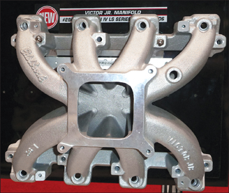
Looking down into a single-plane manifold, the difference in potential wall film area between single point fueling (CFI or carburetion) and multipoint EFI becomes evident. With single point fueling, the entire manifold has the potential to hold deposited fuel affecting transient behavior.
During an acceleration event, airflow in the port is rapidly increased. This increase in airflow tends to evaporate the wall film of fuel on the port. If this wall film reduces in magnitude, its overall contribution to the cylinder fueling is also reduced. The net result is a slightly leaner fuel mixture being delivered to the cylinder during acceleration. Left unchecked, the leaner mixture leads to a reduction in torque output until balance is restored to the wall film contribution. If the driver applies an increase in throttle, he is expecting a corresponding increase in torque output. A momentary lean condition is in direct conflict with this request, so a solution must be found. Some extra fuel must be injected into the port to offset this temporary wall film reduction and cylinder enleanment. This extra fuel shot is the EFI equivalent of a carburetor’s accelerator pump.
To a lesser extent, there is also a need to offset the opposite condition during deceleration. When the throttle is closed and airflow drops dramatically, the fuel film can grow significantly on the port wall. This increased fuel film mass on the walls translates directly into an increase in fuel mass delivered to the cylinders as it evaporates. Carbureted systems simply allow the engine to run richer momentarily. Better emissions and fuel economy can be achieved by reducing this effect if the controls are present to do so.
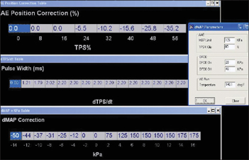
Acceleration enrichment fuel delivery is handled through its own group of tables that are adjustable with respect to throttle position, manifold pressure, and rate of change. It’s important to have the steady state fuel delivery correct before attempting to adjust these tables.
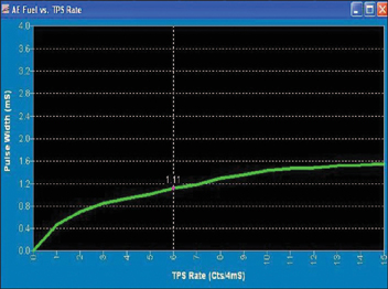
Rapid changes in throttle angle mean that an increase in air charge will soon follow. An additional fuel pulse is determined based on the rate of TPS opening.
There are several different methods that various ECUs can use to apply the necessary acceleration enrichment. The simplest method is to provide additional fuel delivery based on changes in the TPS sensor or MAP sensor output. Since it is the opening of the throttle in the first place that starts the chain reaction that results in different air and fuel delivery to the cylinder under changing conditions, the TPS sensor can be used as a good predictor of upcoming changes. If a positive change in TPS position is detected, it’s a fair conclusion that some amount of additional fuel must be added to offset the change in wall film contribution. In a carburetor, this is accomplished by the mechanical linkage between the throttle arm and accelerator pump. In a simple TPS-based acceleration enrichment strategy, it is accomplished by the graph above right that shows additional fuel mass as a function of TPS rate of change. The rate of change is usually displayed in degrees of throttle rotation per second. Larger changes in throttle angle correlate with the need for even greater additional fuel mass to offset the evaporating wall film.
Just like the throttle angle, the ECU can also monitor manifold pressure to detect highly dynamic changes in load. If the MAP sensor detects a rapid increase, it is also safe to assume that fuel mass must be increased to go along with it. A table of delta-MAP, or MAP rate of change, can also be used to estimate the necessary fuel mass increase. Some systems employ both a delta-MAP and a delta-TPS table that are summed to provide the total additional fuel mass during transient conditions.
A more elegant method of calculating the necessary fuel addition is by actually modeling the behavior of the fuel wall film. For each injection event, a percentage of the fuel injected sticks to the port wall instead of being carried directly into the cylinder. This percentage is referred to as “X” and varies significantly with temperature and load. At low temperatures, the percent of fuel effectively condensing on the cool port walls is much greater with each shot. As the engine and port walls warm up, fuel is less likely to stick and the X component decreases as seen in the top graph below. Likewise, changes in load or airflow will also affect the amount of fuel being deposited upon the port walls.
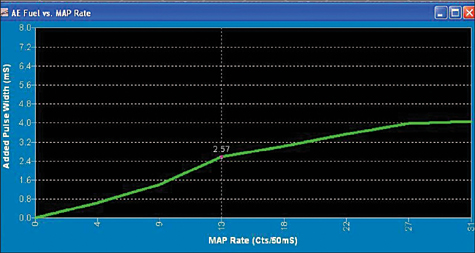
Acceleration enrichment can also be added based on changes in measured manifold pressure. This works well on turbocharged engines that may see many different boost values at the same throttle angle.
Once the fuel is deposited upon the port wall, it will evaporate over time. The rate at which it evaporates also depends upon temperature and load. Higher temperatures help evaporate the film quicker, as does lower manifold pressure. The time constant for evaporation is referred to as “τ” or the Greek letter Tau. A larger Tau value means faster evaporation. Another way to think of Tau is the portion of fuel delivered to the cylinder directly from the wall film.
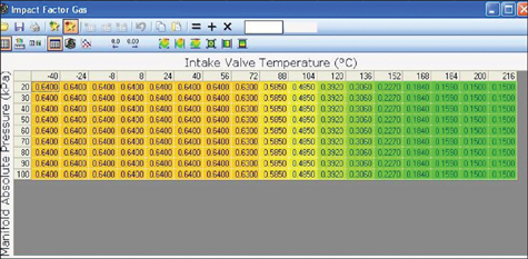
A true X-Tau system will have a table similar to this that defines the fraction of injected fuel that collects on the port wall. This amount of deposited fuel decreases significantly as engine temperature rises.
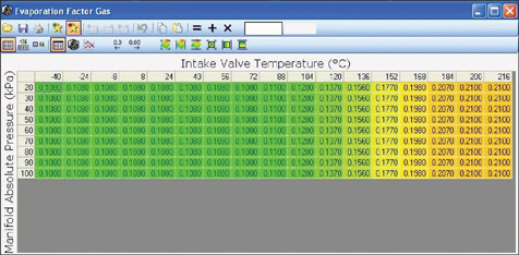
The evaporation factor (Tau) is also strongly tied to operating temperature. This is a snapshot of the OEM table in a 2009 LS3 Chevrolet Corvette as seen with HPTuners software.
With either compensation method, the calibration procedure remains basically the same. The best method is to apply a single, positive change to the throttle position between two fixed points. Performing the test at part throttle is easiest since the engine would be going from a commanded lambda of 1.00 at the first point to a commanded lambda of 1.00 at the second point. The test is performed starting from a steady state condition and ending at another steady state condition, both of which are known to have good VE estimation and fuel delivery control. Since the beginning and ending air/fuel ratios are the same, there should be noticeable change in delivered air/fuel ratio. However, there almost certainly will be some momentary deviation if no wall film correction is applied. The objective is to add just enough wall film correction to achieve as close to zero lambda deviation as possible during the maneuver. Too little and a lean spike is shown along with soggy throttle response. Too much and a momentary rich condition is seen.
For example, one may choose to test going from 2,000 rpm and 50 kPa to 2,000 rpm and 70 kPa. This simple tip-in event is typical of a normal traffic event in the vehicle. A load-bearing chassis dyno can make this task much easier if it is set to perform a constant-speed test during the initial VE mapping. Keeping the engine speed constant helps to reduce the number of variables during the test. Just stabilize the vehicle at 2,000 rpm and a measured load of 50 kPa with the engine at normal operating temperature. The delivered lambda should read right on the commanded 1.00 ratio and there should be minimal fluctuations in TPS, MAP, and lambda. The driver can then tip into the accelerator to increase load up to, but not exceeding, the new target of 70 kPa. It is very important to resist the temptation to release the gas pedal after hitting the higher target load. The objective is to only get a positive change, not a positive followed by a negative.
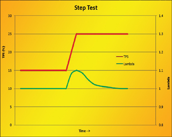
By performing a single step change in throttle postion, the calibrator can see if the transient fuel tables require adjustment. It’s important to only make a single positive or negative change and allow the delivered fueling to stabilize to isolate the transient effect.
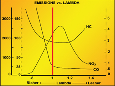
Remember this graph from earlier? During a positive transient, it’s important to avoid going lean and losing torque to make sure the driver actually gets a torque increase when he presses the gas pedal.
If the delivered air/fuel ratio peaks above lambda=1.00, the acceleration enrichment values must be increased and the test repeated. Increases can generally be made globally to the entire acceleration enrichment table as a percentage since the root cause of the momentary leanness is typically a function of the injector spray geometry and engine efficiency. Since the injector spray pattern remains constant, it’s safe to assume that this change is almost universal for the engine in question. The test can be repeated for varying rates of throttle application to make sure that both gentle and aggressive events are properly compensated for.
If adjusting a Tau map, additional enrichment can be realized by reducing the Tau value at the second target point. When the ECU calculates that a smaller amount of fuel is being delivered from the (now smaller) wall film, it will automatically increase the fuel mass delivered from the injectors. Large negative changes in the Tau value will tell the ECU that it must provide greater compensation in the base pulsewidth delivery.
If it’s not possible to get exactly zero change from the target of lambda=1.00 throughout the transient test event, it’s best to err on the side of richness. A slightly rich mixture makes more torque than a stoichiometric mix. The added torque from a little richness actually feels good to a driver who has essentially requested more torque by tipping into the throttle. Going excessively rich can be counterproductive though, so avoid getting “too much of a good thing” here. There’s no sense in wasting fuel with extra acceleration enrichment beyond a value of lambda≈0.92 if at all possible. An ideal case for most street driven vehicles would be only a momentary deviation to lambda≈0.96 followed by a quick return to stoichiometric operation in steady state.

There’s no place for an accelerator pump on this intake manifold. All of the transient fuel delivery must happen through the eight individual injectors based on input from the TPS and MAP sensors.