Figure 18.1
Holding fixture for freewheel
18
Freewheels, Freehubs, and Clusters
Types
There are two types of multi-speed freewheel systems: the older freewheel system, in which a unit consisting of both the sprockets and the freewheel mechanism is threaded onto the rear hub, and the newer freehub system, in which the freewheel mechanism is part of the hub and the sprockets are slid onto it.
Freewheels
Freewheels and clusters are classified by number of speeds, by spacing between sprockets (chain width), and by assembly method. The number of speeds ranges from one to eight. A one-speed freewheel is used on one-speed bikes; two-, three-, and four-speed clusters are antiques. Clusters of from five to eight speeds are used on modern derailleur bikes. With clusters having one to three speeds, ⅛-inch chain is used. Narrow 3/32-inch (2-mm) chain was introduced for four-speed clusters and then used for five-speed clusters. Some six-speed clusters used this chain also. Later, six-, seven-, and eight-speed clusters used ultra-narrow, flush-pin chain, also 3/32 inch (2 mm) but without protruding pin heads. Each width of chain has its own spacing between sprockets, a difference that you can see by comparing different clusters.
Sprockets are assembled onto freewheels by three different methods. In the oldest method, all the sprockets are screwed onto the freewheel body. In the next development, all the larger sprockets are slipped over splines on the body and are held in place by screwing on one or more of the small sprockets. The latest development is a cluster that is riveted together and cannot be disassembled. Of these, the splined type is the easiest to service.
Tools
You need the correct type of freewheel remover to remove the freewheel from the hub. There are two requirements: the remover must have teeth that match the slots in the freewheel, and the remover must be shaped so that it will fit over the axle end (so that you don’t have to remove the axle to remove the freewheel). Most modern removers will fit over the end of the axle. The slots in the freewheel into which the teeth of the remover fit may be either splines or plain slots. Splines are slots that are shaped like the teeth of a gear; the proper remover slides into them. Plain slots are like the slot in the head of a screw, and the remover is shaped like a giant screwdriver.
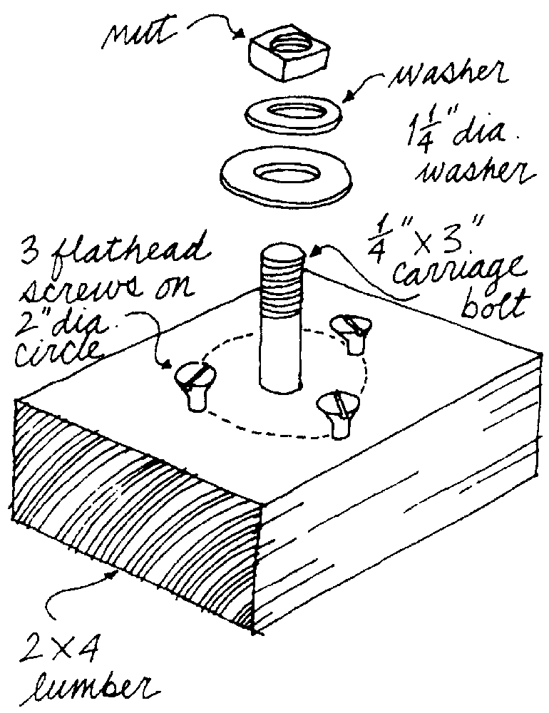
To disassemble a freewheel, you will probably need a pair of chain wrenches, steel bars with short lengths of chain attached near one end for unscrewing the sprockets. To use the chain wrenches, wrap the chain around the sprocket, put the tip of the bar between two teeth, and pull on the bar. Two wrenches are required: one to hold the freewheel by one sprocket as you unscrew another sprocket with the other wrench. It is also handy to use a freewheel fixture made by putting a bolt through a block of wood and using a big washer and nut to hold the freewheel to the wood as you work (figure 18.1).
Figure 18.1
Holding fixture for freewheel
The block can be either small enough to be held in a bench vise or large enough to kneel on as you work. If your freewheel has its largest sprocket screwed on, install three screws in a circle around the bolt hole to hold the freewheel ½ inch above the surface of the block so that you can unscrew the largest two sprockets.
An alternative chain wrench that works only for freewheels with only one screwed sprocket (the smallest) consists of a short length of chain attached to a hook. This tool prevents the smallest sprocket from rotating when the rest of the cluster is rotated by the bicycle’s chain. To use this tool, shift the bicycle’s chain onto the largest sprocket. Then place the tool’s hook onto the chain stay just forward of the smallest sprocket and let the tool’s chain hang down in front of that sprocket. Then wrap the tool’s chain around the smallest sprocket, going back, then up, and finally forward over the top of the sprocket. Then pedal forward. The freewheel will rotate forward except for the smallest sprocket, which will unscrew because it is held by the chain and the hook.
Removing a Freewheel
If your freewheel is a slotted type, slip the freewheel remover over the axle and hold it on with the axle nut or the quick release. Because it may take a lot of force to break the freewheel loose, the tool and the freewheel will be damaged if the tool jumps out of engagement while you are trying to do it. So bolt it on quite snugly. (You may need a large washer to bridge the gap between the nut and the hole through the remover.) Splined removers don’t need to be fastened so firmly, because they aren’t forced out by the torque. Apply the wrench to the remover, or hold the remover in the jaws of the vise. The freewheel is right-hand threaded, so unscrew it as if you were pedaling backward. The moment the freewheel turns a bit, loosen the hold-down nut one turn and unscrew the freewheel until it reaches the nut again. If you don’t unscrew the axle nut or readjust the quick release, unscrewing the freewheel will pull the axle through the hub, damaging bearings or breaking the quick-release skewer. Alternate loosening the nut and unscrewing the freewheel until the freewheel is loose enough to unscrew by hand.
Cleaning and Lubricating a Freewheel
Dunk the freewheel in solvent, up and down, until it rotates freely with no signs of grit inside it. Then dunk it in oil (SAE 90) and drain it, or apply oil from the small end until it runs out the big end. Test it to see that it runs smoothly. Grease the threads on the hub. Then replace the freewheel by screwing it carefully onto the hub. If you have a splined remover, use this as the guide to help prevent cross-threading the freewheel onto the hub and ruining the hub.
Disassembling a Cluster
If the freewheel does not run smoothly after cleaning, if the outside ring wobbles on the inside body too much, or if the freewheel doesn’t catch when driven forward, you must disassemble it. Also, if any of the sprockets has its teeth worn into a hook shape, or bent, it must be replaced. The first job is removing the sprockets.
Bolt the freewheel onto the freewheel fixture that you have made and hold the fixture in the vise or kneel on it if you have mounted the fixture on a board. Alternatively, you can remount the freewheel on the rear wheel and use it to hold the freewheel body while you work on the sprockets.
If your cluster has only screwed-on sprockets, you must unscrew them in the precise sequence described later in this chapter. If you don’t know how your cluster is assembled, start by following the instructions for screwed-on clusters. When you get the first few sprockets off, you will know whether the rest are splined or screwed on. The sprockets all unscrew by turning them backward, but you can do it only in one sequence. Because they have been screwed on by the full weight of your body on the pedals, they require strong arms to unscrew them.
Call the largest sprocket #1, and the smallest #5, #6, #7, or #8, as applicable. Note carefully that all sprockets screw on in the direction of pedaling and screw off as if you were backpedaling. Sprockets #1 and #2 come off the back, whereas #3, #4, and #5 come off the front. Thus #1 and #2 are left-hand threaded, but don’t worry about it as long as you unscrew in the backpedaling direction.
This is the disassembly sequence. Hold the next to the smallest sprocket (#4 of a five-speed cluster) and unscrew the smallest sprocket (#5 of a five-speed). Continue holding the next-to-the-smallest and unscrewing the smallest until either #3 is the next to be unscrewed or you reach splined sprockets that can just be lifted off.
If you reach splined sprockets, lift them off as well as the spacers between them. A little prying might be needed. The larger sprockets will probably have larger splined joints than the smaller ones, and the spacers will probably be of different sizes. Therefore, keep track of the sequence in which they come off.
If you reach #3 and it is screwed on instead of splined, you will have to change your sequence of operation. Here only one sequence will work, so follow it carefully. Hold #3, and unscrew #1 no more than two turns. Hold #3, then unscrew #2 until it locks against #1. Screw #1 against #2 to lock them together. Hold #1, and unscrew #3 completely. Hold #2, then unscrew #1 to unlock them. By hand, unscrew first #1 and then #2. Getting #1 loosened, or getting #3 loosened after using it to loosen #1, is generally the hardest task, because #1 has been screwed on by heavy driving in low gear.
Disassembling a Freewheel
A freewheel is a cup-inside, cone-outside bearing design like a pedal, but with several differences. There is no lock nut. The outer cone unscrews clockwise—this is the ring in the small end that has two small holes in it for a pin wrench. Adjustment is accomplished by altering the number of spacing shims between the outer cone and the body.
Remount the freewheel on the hub to hold it steady, and unscrew the outer cone with a pin wrench or by inserting a nail or a punch in one of the holes and driving it around with a hammer. Remember to unscrew the outer cone clockwise. If the freewheel was merely too loose, unscrew the cone while holding the outside ring down firmly to keep the parts together. Then remove one shim washer from the stack under the cone and replace the cone. Make sure that this hasn’t tightened the bearings too much. If there is no play left, replace the shim and accept the amount of play there is.
If the freewheel is stuck, won’t latch, or is noisy, once you have lifted out the cone, lift off the outer ring. Inside are many balls, and two or three pawls with springs. Catch everything that falls out. If the freewheel failed to catch, and if it uses pawl springs made of fine wire, the ends of the springs may have become worn too short to operate the pawls. Make new springs from music wire or, in an emergency, a strand from a brake or gear cable. Examine for broken pawl tips, worn pawl springs, broken balls, and pitted races. Recount the balls into each race separately, and add more balls if there are too few to fill the race, as often seems to be the case.
Reassembly is done in the reverse order. Use grease to hold the balls in the races during assembly. Make sure all the pawls and springs are correct. Hold the pawls in by wrapping one turn of thread around the assembly. Lower the ring over the assembly, and pull out the thread. You may well need several tries before it goes together properly. Oil it well before using.
New Chain, Old Sprockets
A new chain and a new sprocket are designed to run smoothly together, as shown in figure 18.2.
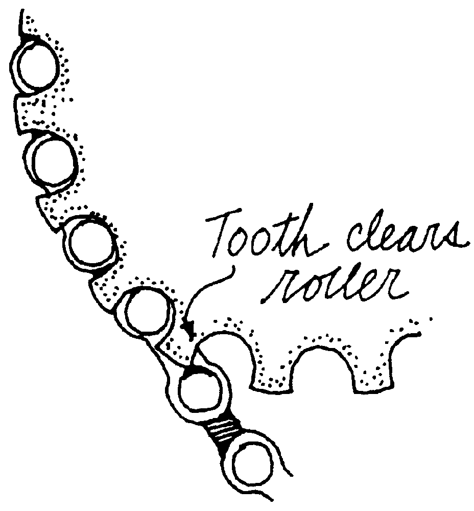
Figure 18.2
New chain runs smoothly onto new sprocket
However, a new chain may run roughly on old sprockets. The new chain may feel fine on the test stand as you twirl the pedals, but when you drive hard on the road, your pedals may jerk forward with loud clanking. This happens because the sprocket is worn to fit the longer links of the old worn-out chain. Look at the sprocket teeth. The backs of sprocket teeth, and the fronts of chainwheel teeth, wear into a hook shape from contact with the chain under driving force. At a back sprocket, for instance, a link of the chain feeding onto the sprocket snugs down tightly into the hollows between the teeth. Then the next link feeding on just clears the top of the next tooth. As the chain wears into the root of the tooth, the clearance between the next link and the top of the next tooth lessens, but is compensated for by the lengthening of the links as they wear. When you put on a new chain, its links are too short to clear the unworn tip of the next tooth, as shown in figure 18.3.
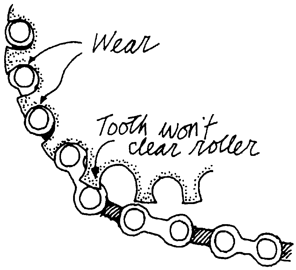
Figure 18.3
New chain runs roughly onto old sprocket
As long as the chain is under a light load, the chain roller rolls down the back side of the tooth, but when you drive hard, the chain is snugged forward in the hollow and won’t back off enough to let the roller roll over the point of the tooth. So the chain starts to run on the tips of the teeth. When the sprocket turns enough so the chain feeds off the teeth in front of this bulge in the chain, suddenly you are trying to drive with a chain resting on the tips of the teeth. The chain slips forward until it catches in the next tooth forward with a jerk and a clank.
The traditional answer is to replace the sprockets if this happens. However, you can refinish sprocket teeth (figure 18.4).
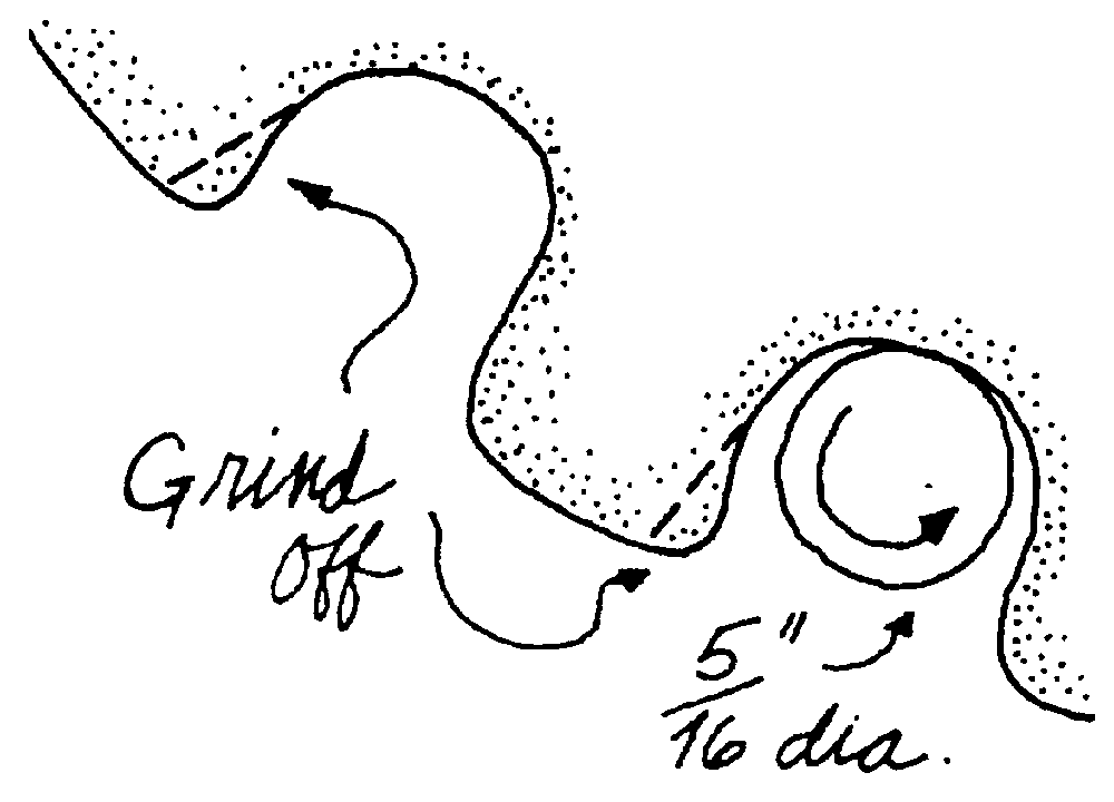
Figure 18.4
Grinding hooks from sprocket teeth
The curve of the valley between sprocket teeth is about 5/16 inch in diameter. Get a 5/16-inch-diameter grinding point. Use it to grind off the unworn hook point until the tooth is restored almost to the original contour over its whole working face, giving it many more miles of life.
Freehubs
With freehubs, the freewheel mechanism is part of the hub, and the sprockets can be removed while the freewheel mechanism remains intact. The outside of the freehub has a splined surface onto which the sprockets slide. With some designs, the cluster of sprockets is retained by the outer sprocket, which is screwed on. With other designs, the cluster of sprockets is retained by a C-clip or similar. If the outer sprocket is screwed on, remove it by using a pair of chain wrenches. The sprockets may come off separately, or as a cassette. If separately, keep track of the spacing washers between sprockets. Replacement of the sprockets is commonly done for all at one time as a cassette.
The freehub is much longer (wider) than the typical freewheel mechanism. Thus its bearings are farther apart, giving better control, and it provides more space for the ratchets and springs that produce the freewheeling function. Therefore, it rarely needs service. It can be removed from the hub by releasing the outer retaining clip or ring, washed in solvent, re-oiled, and replaced. The bearing races may be removed and the balls replaced, in the same way as for freewheels. Other replacement inner parts are not obtainable.