CHAPTER IV
ANVILS AND ANVIL TOOLS
HOW ANVILS ARE MADE.1
“So the carpenter encouraged the goldsmith, and he that smootheth with the hammer him that smote the anvil.”
This is the first and only mention of the anvil found in the Bible. But it is of more remote origin even than the prophet Isaiah, as we read of Vulcan forging the thunderbolts of Jupiter, and he must, of course, have had an anvil of some sort for that style of blacksmithing; probably, however, nothing better than a convenient boulder.
The anvil and the anchor are two of the oldest implements known, and for thousands of years about the only ones that have not changed in general form.
The modern “vulcan” now has a hardened steel face provided with the necessary holes for his swedges, which with the round projection at the other end terminating in a point, called the “horn,” is sufficient for every kind of work.
Except those made in the United States, every manufacturer of anvils has a body of wrought iron under the steel face. The horn also is simply of wrought iron. With slight modification, the method of making these has not changed for hundreds of years.
The body is roughly shaped out under tilt hammers. In the better grades this is in one piece, and called “patent,” while in the German and most English works the four corners and the horn are “jumped” on in separate pieces. Though called “wrought” this is of the lowest grade of iron, adopted both on account of cheapness, and because the subsequent process of welding the steel face to it is easier than with the more refined of these materials.
For the same reason only the lower grades of steel—viz., “shear” steel, or even “blister” steel, are used for the face, cast steel never being used on account of the greater uncertainty of a perfect weld under the hammer to a large mass of wrought iron.
The common grade of English anvils and all those of German make weld the steel on in two or three pieces according to the size of the anvil; the best English brand, however, of late years, has the face in a single piece of shear steel.
For this the wrought iron mass is brought to a welding heat, as also the steel plate, the welding of which begins at one end.
Four strikers swinging heavy sledge hammers together, do this welding in portions of about five inches of its length at a time, and this process is continued by successive heatings until the whole length of the face is finished.
The cutter hole and the small round hole in the tail are then punched out, the iron horn rounded off, and the whole dressed up into its finished shape at a subsequent heating. By long years of experience at this work a symmetrical, good-looking job is made.
Any inequalities or imperfections in the face are taken out by grinding crosswise on a large stone, and the anvil is then ready for the final process of hardening.
This is done by reheating the upper portion to a red heat, and a stream of water is let down upon it under a ten-foot head. The temper will be more or less uniform according to the quality of the steel which has been used, and the greater or less care in the heating at the previous stages. The soft spots so much complained of by blacksmiths are due to these inequalities of the material and workmanship. The thickness of the steel used varies from three-eighths to three-quarters of an inch, according to the size of the anvil.
The whole process is almost entirely one of manual labor and judgment. Extreme care must be used not to burn some portions of the steel during the welding operation, resulting in cracked faces and crumbling edges, which the blacksmith frequently finds to his sorrow developed in his anvil, apparently of the best when new.
A perfectly welded, wrought iron anvil has a clear “ring” when struck; otherwise it is a pretty good sign that there is somewhere an imperfection.
From the nature of the operation as above described, it is evident that the size of such an anvil must be limited. They vary in weight from one hundred to five hundred pounds; the largest ever made being one exhibited at the Philadelphia Centennial, which weighed 960 pounds.
There are no wrought iron anvils made in the United States. As it is almost entirely a question of skilled manual labor, and as there has never been any but a nominal duty imposed (it is the same as on spikes, nuts, and washers), all the wrought anvils used in this country are imported from Europe.
In 1847, the late Mr. Mark Fisher, believing in the possibility of welding cast steel to a high grade of cast iron, which had up to that time been unknown, discovered a perfect and successful process by which the two metals could be welded together in any desired dimensions. [The largest anvil in the world was made by the Fisher Eagle Anvil Works for the Centennial Exposition in 1876. Its weight was 1,600lbs.] The value of this process for anvils was apparent, as there could thus be obtained a perfect working surface of the best quality of cast steel, capable of hard and uniform temper on a body which from its crystalline and inflexible structure would never settle or get out of shape in use—one of the defects liable to occur by continued hammering in anvils with a fibrous wrought iron body under the steel.
It also enabled a steel working surface to be applied to the horn, which previously had been only of plain iron.
The first manufacture of these anvils in this country began under his patent in 1847, and though requiring many years to perfect and establish this new and essentially American anvil, it is now recognized as a better article than the old-fashioned imported kind, over one-half of the anvils used in this country, it is said, being made by this process, and so certain and successful is it that they are the only ones in the market fully warranted against breakage, settling of the face, or failure in any respect.
It is needless to say that ordinary cast iron would not answer for a tool subject to such severe usage as an anvil.
The metal employed must have a strength equal to that in gun castings, a certain elasticity to stand the strain of high heating and sudden cooling of the tempering process, and perfectly sound in all parts. Though many so-called “cast” anvils have from time to time come upon the market, only one concern in the country, and that the original one operating under the Fisher patents, has continued to produce anvils with all the qualities described as necessary in these tools. The mode of manufacture is naturally quite different from that of wrought iron anvils.
The steel used is one piece for the face, of best tool cast steel.
The anvil is cast bottom side up, having this steel, as also the steel horn, placed in the “drag” or lower part of the mold.
Before filling it with the metal, which is not only to form the body of the anvil, but also to effect in its passage the perfect welding required, the steel face and horn are heated to a bright color, and every part of their exposed surface is covered by the molten metal. After the necessary annealing this rough anvil is removed, trimmed, planed true, and put into its finished shape, the cutter-holes made exact, and it is then ready for the hardening and tempering process. This last is the crucial test, for both iron and steel must be heated to a high point and then suddenly plunged into the cold hardening liquid. Should there be any spot between the two metals not perfectly welded, the steel will separate, or the whole anvil will crack and fly into pieces; so that if it passes this stage successfully it is reasonably sure to be perfect, and therefore the makers can safely give a full warranty to the purchaser.
Recent improvements have added much to the value of this make of anvil. By extending the steel part of the horn down into the body, all danger of breakage of the horn where it joins the main part is prevented. Also both edges of the steel face are made of double thickness, which prevents crumbling or splitting off of those places most exposed to severe usage, so common with the old-fashioned anvils.
Two peculiarities distinguish the American from the foreign anvil. They are more solid from the crystalline structure of the body, and therefore do not bounce back the hammer or sledge, thus retaining all the effect of the blows in the piece worked on, and the steel face always retains its original true surface for the same reason. Also there is very little “ring” in them, and this peculiarity is sometimes urged as an objection by those accustomed to the wrought iron anvils.
Nearly every metal trade has its special form of anvil, and differing from that of the blacksmith—such as saw, axe, razor, silversmith, coppersmith, shovel, hoe, plough, and many others, which are simple blocks of iron with steel faces, made by one or the other of the two above-described distinct and opposite methods and materials.
The annual importations of anvils from England and Germany into the United States exceeds one and a half million pounds.
The price of all anvils is now less than one-half that of former times, when we were compelled to obtain our entire supply from foreign manufacturers and importers, and before the discovery of the process above referred to made American competition possible.—By “EXPERT.”
DRESSING ANVILS.
The expression, “I wish my anvil was dressed,” can be heard every few weeks in very many blacksmith shops. The work which the smith has to do oftentimes requires some little thought in the make-up of the anvil in which it is deficient, hence a considerable hammering of the iron is required to obtain the shape wanted. I have noticed that nearly all the new anvils I have seen are wrong in the design of the face. The corners of both sides toward the horn, half way the length of the face, should be rounded to the radius of about one-quarter of an inch. This prevents the cutting of small fillets which are often required in iron work for strength, and enables the smith to get his work near the anvil without danger of cutting the fillet. This is a source of comfort in many cases. It is also more agreeable to scarf iron on a round corner, because it does not cut the scarf and cause it to break it, as a sharp corner does.
To dress an old anvil requires some knowledge. It is necessary to know how to go about it. In the first place, if the shop is provided with a crane it will be found useful in the work to be done. The tools required to handle an anvil are two bars of 11/4 inch iron, one of them six or eight feet long and the other five feet long, according to the size and weight. The length of the bars can be chosen for the work according to the smith’s judgment. The carrying bars are pointed to fit the holes in the anvil under the heel and horn and also the bottom. These holds afford the most convenient way of holding an anvil either in forging it or dressing it. The construction of the fire is a most important feature of the work in hand. Throw away the fine burnt coal that is around the fire, and build the fire large enough with good, fine soft coal. Do not be afraid of using too much coal, because in rebuilding the fire there will be plenty of coke, which will be found useful. When the fire has obtained a good bottom, place the anvil face nearest the horn on the fire, thus heating parts of the face at a time. Next put some fine cut pine wood alongside the anvil, about 3 inches high and 8 or 10 inches long, and cover it all over with soft coal. When the wood burns out there will be a hollow space around the part that is being heated, which will allow free circulation of heat and flame. By this plan it will also be possible to see into the work through the openings made in front through the crust of the coke or fire cover. Through these openings on either side the operator can feed the fire with broken coke as it burns away. If the top burns through, recover the burnt parts with fine soft coal in time so that it will not fall. Do not let the coke touch the face underneath, because it hinders the proper heating.
When the anvil is hot enough, place it on the floor or block, as may be deemed best, and then let two men work up the sides together at the part heated with their hammers. This brings up the metal to build out the corners with, and also to level the roundness of the face. Smooth every part heated with the flatter or hammers as much as possible, because this lessens the work of grinding the face. Use a square in order to see that the work is level. Heat again along the face and finish. When it comes to the heel, have a square pin to drift the hole out, so that it will not be necessary to alter the tongs of the bottom tools employed in it. Round off the corners for about eight inches on each side of the horn. Further out let the corners be sharp. If a piece is broken off the corners, make a wedge of tough toe-calk steel, amply large enough to fill the space. Have a clean fire and plenty of coke to bank up with. Heat the broken part and raise up the edges with a fuller, rounded to about the size of a silver dollar, 3/8 of an inch thick; then, when hot enough to work, sink the chisel in far enough for the purpose and drive the steel wedge in the opening thus formed. Then heat until soft enough to work and fill up the space. Sprinkle the iron with cherry heat welding compound in such a manner that it will get between the iron and steel. Heat slowly with plenty of clean coke and flux with compound. If the heat is good there will be no difficulty in working with hand hammers. Cut off the waste on the side with a sharp chisel. If the horn wants setting up a little, it may be next taken in hand, as there will be sufficient coke to cover it. Do not let the point of the horn set above the level of the face, because it interferes with straightening along the iron.
To heat the anvil for hardening, place supports under the carrying bars when they are in the anvil. This prevents the anvil settling in the fire. Keep the coal from the face. Build with fine kindling wood all along the sides and heel. Cover with soft coal, not too wet, then blow up. When the wood is burned up, open a hole through the back and front of the fire for circulation. When the anvil is red hot on the face it is ready to harden. Lower it in a box of water until there is about three inches over the face. A piece of chain with hooks to it, passing around the horn and underneath the heel, the point dropped through the hole to prevent the chain slipping, a long bar passed through the chain loop, will be sufficient to keep the operators far enough from the steam to prevent danger from scalding. A stream of water from hose on the upturned face of the anvil will quickly cool it, or pails of water speedily used from an extra supply barrel will answer. Anvils are usually hardened, not tempered. The grinding can be done with a travel emery wheel, or the anvil may be hung with a rope or chain in front of the breast of a stone driven by machinery. Taken thus, it may be passed to and fro across the stone, and twisted and turned without the least inconvenience from its weight.—By C. S.
SHARP OR ROUND EDGES FOR ANVILS.
“Would an anvil of any make be more convenient if both edges of its face were to be rounded for one-third or one-half its length?”
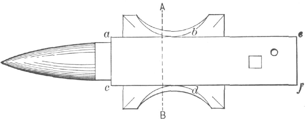
FIG. 54.—SHOWING THE EDGES
It is not my desire at this time to discuss the relative merits of different makes of anvils. What I would like to know is whether, in any anvil, there is any reason for having the edges that are represented by the lines a b and c d, in Fig. 54 of the accompanying illustration, sharp instead of rounded to a curve of a quarter of an inch or more radius?
I believe that it is impossible to forge an interior angle sharp and have the forging round. It does not matter how small the work, nor how insignificant the shoulder that is formed by the re-entering angle, if sharp in the corner, the structure of the iron at that point is destroyed and the forging weakened. The weakness may not at first be apparent, the forging may look well enough, for it is only in exaggerated cases that the crack or “cut” is actually found. Now, if it be a fact that sharp inside corners in the work cannot be made safely, what possible use can there be for sharp outside edges on the anvil? True, I have seen blacksmiths cut off excess of stock over the edge of the anvil when their hardy was duller than the anvil; but who will defend them in such an operation?
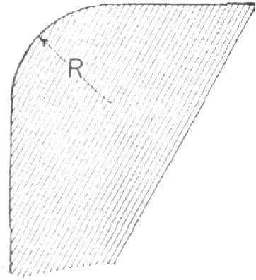
FIG. 55.—PARTIAL SECTIONAL VIEW OF ANVIL SHOWING ROUNDED EDGES
For my own part, I am satisfied not only that the sharp edges are useless, but that they are also destructive of good work. I cannot account for their existence except as a relic of a time when the principles of forging were but little understood. I want both edges of my anvil rounded, not simply for a part of their length, but for their whole length. To my mind the ideal anvil of 130 pounds is one having its edges from a to b and from c to d, Fig. 54, rounded to a curve of three-eighths of an inch radius (as at R, Fig. 55, which is a partial section enlarged on the line a, b, Fig. 54), and its edges from b to c and from d to f rounded to a curve of three-sixteenths or one-quarter of an inch radius. The edge from e to f can be sharp to satisfy the unconverted.—By X.
DEVICE FOR FACILITATING THE FORGING OF CLIPS FOR FIFTH WHEELS.
About fourteen years ago I was engaged in the manufacture of fifth wheels on a small scale, and having to devise appliances and often to extemporize means to more effectually facilitate matters, among other “kinks” I introduced the following, which has given me a good return for the trifling change it makes in the usual method of using the “ass” of the anvil. It is well known that in the ordinary style of working this part of the anvil soon becomes imperfect or depressed, as shown at D in the accompanying illustration, Fig. 56. My plan is to drill immediately below the steel face, and about two inches from the front end of the anvil face, three 3/4-inch holes, thus forming a round angled triangular hole, C, through the anvil. On removing the core left, I have a conveniently shaped hole that will accommodate almost any size clip, and enable me to swage it very true, quick and perfect, with less effort to retain it square, than is required by the old plan. I have not seen this idea put into practice anywhere else, although, having been otherwise engaged for the last twelve years, it may have been used by others without my knowledge. The hole does not weaken the anvil enough to injure it, and I was surprised at the durability of this portion of the face after two years’ constant use on four or five anvils. They were as good anvils as we could get.—By W. D.
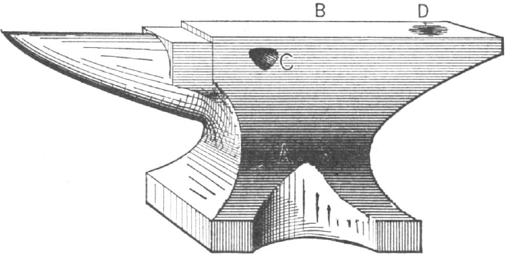
FIG. 56.—DEVICE FOR FACILITATING THE FORGING OF CLIPS FOR FIFTH WHEELS
PUTTING A HORN ON AN ANVIL.
I have put three horns on broken anvils, and I have worked on one of these anvils for fourteen years. My method of doing the job is as follows:
I first cut the mortise, cutting in straight about three-quarters of an inch, then cut out the corners; of course it has to be done cold. Commence well down below the steel, then lay out the tenon on the horn, heat it and cut with a thin chisel, fit tight, and drive together with a sledge. If there are any open places between the anvil and horn, drive in thin wedges as hard as possible. Cut off very close, and take the fuller and head the iron over them, and then put in the die and head that in. If it gets a little loose after a while, take the fuller and head it again. It has always taken me about a day to do this job. In the accompanying illustration, Fig. 57, is shown my way of doing it. A represents the dove-tail mortise, B is the horn, and C is the die used to fill up the mortise after the horn is driven to its place.—By C. H.
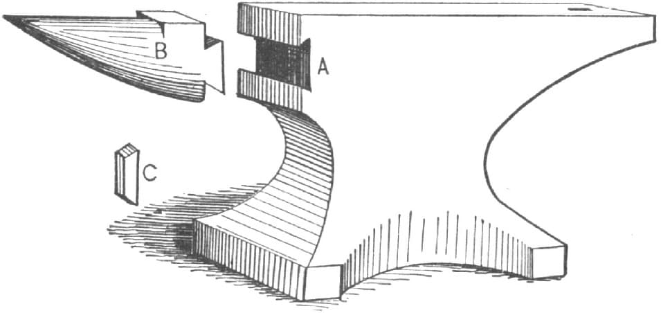
FIG. 57.—PUTTING A HORN ON AN ANVIL BY THE METHOD OF “C. H.”
FASTENING AN ANVIL TO THE BLOCK.
A simple and effective way to fasten an anvil to a block is to make a square iron plug to fit tightly the hole in the bottom of anvil, and a similar hole in center of block. Then you can have the block just the size of the anvil and no fixings in the way, or even in sight.—By WILL TOD.
FASTENING ANVILS.
Concerning the proper method of fastening anvils in position, I would say that it only requires to flatten each corner of the anvil. Drill a half-inch hole and pass a half-inch square-headed bolt, ten inches long, down through the hole into the block, with the nut so arranged as to receive the end of the bolt. By fastening the anvil in this way there will be no obstructions whatever. I am not able to send a drawing of this means of fastening an anvil, but think every practical smith will readily understand it from the description.—By J. W. F.
HOLDING AN ANVIL TO THE BLOCK.
To fasten an anvil to the block, I use a chain of the proper length with an eye bolt. It is passed over the anvil, and the eye is then screwed into the block on the front and back.
The eye bolt is then passed through the eye in the block and screwed down until it is tight. When fixed in this manner an anvil cannot move. The device is so simple that it is not much work to make it.—By H. N. P.
SHARPENING CALKS—A DEVICE FOR HOLDING SHOE AND OTHER WORK ON THE ANVIL.
In all places where the roads are icy, it pays those who use horses to have steel calks in the heels as well as in the toes of their shoes. In different places where I have worked various methods have been employed to obtain a self-sharpening and durable calk. The best plan I have ever tried is to split the heel-calks with a thin chisel, and insert a piece of steel (old sickle sections are good) previously cut to the proper size; then weld solid, draw sharp, and temper hard. It used to require a helper to hold the shoe with tongs on the anvil, or it would jump off in splitting the heels; but I have studied out a contrivance that I think may be of use to all brother smiths who think my way worth adopting. I will try to explain it, with the aid of the accompanying illustration, Fig. 58, in which C is a foot lever hung in the center by two staples on a right-angle iron, D, which is sharpened at each end, one end being driven into the anvil-block, B, and the other into the floor. To this foot-treadle is bolted or riveted a strap with an eye connected to the rod E, which latter has eyes on both ends, and is connected with FF, which is in one piece of 5/8 round iron, flattened where it comes on the anvil face. Before being bent, F is passed through two eyes which are fastened to the front of the anvil-block with screw-bolts. When a man has no helper, this device is often useful in holding other kinds of work on the anvil for punching, etc., and saves one man’s time. When there is no such work to be done, it can be taken off and laid aside.—By C. H. W.
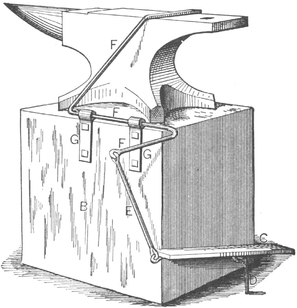
FIG. 58.—DEVICE FOR HOLDING WORK ON THE ANVIL
MENDING AN ANVIL.
I will try to describe a job that was done lately in the shop I am working in.
The base of a wrought-iron anvil had been broken off as shown in Fig. 59. Not wishing to throw the anvil away, the boss told us to try to repair it, and we did it in the following manner:
We first looped a piece of 11/8-inch iron around the end of the anvil, with a flat spot just above the loop on which to catch a hook so as to enable us to handle it better. We next put what I call a binder of 5/8 round iron around the beak iron to prevent the porter bar from slipping off. Next we got out a piece of iron something the shape of the piece A, in Fig. 59, with a bar welded on the side for handling. This piece was about as wide as the body of the anvil. We then put the anvil in the fire to prepare it for welding, which was done by cutting away the uneven places and scoring it with a chisel. We then put the anvil in the fire for a weld, building the fire up especially for it. The piece to be welded on was brought to a heat in a separate fire. When all was ready the anvil was carried out of the fire by the aid of a bar of iron run through the loop, and turned into position by the use of the hook and the flat spot on the bar. The piece was then welded on and put into shape with a big fuller, which left the job as seen in Fig. 60. The side was then scored and the anvil put back into the fire for a side heat while the piece B was made. It was brought to a heat by the time the anvil was hot, and then they were brought out and welded and put into shape like the end piece. The other side was then put through the same process, and the whole touched up with fuller and flatter, which left the job in good shape as shown in Fig. 61, and as good as new.—By APPRENTICE.
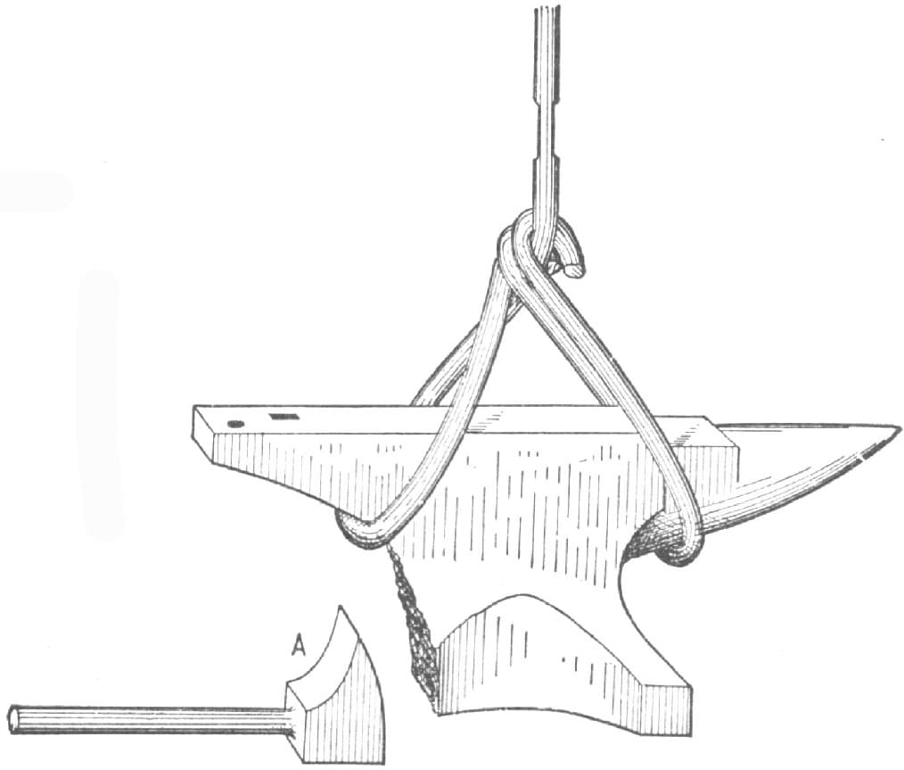
FIG. 59.—THE ANVIL AND THE PIECE USED IN MENDING IT
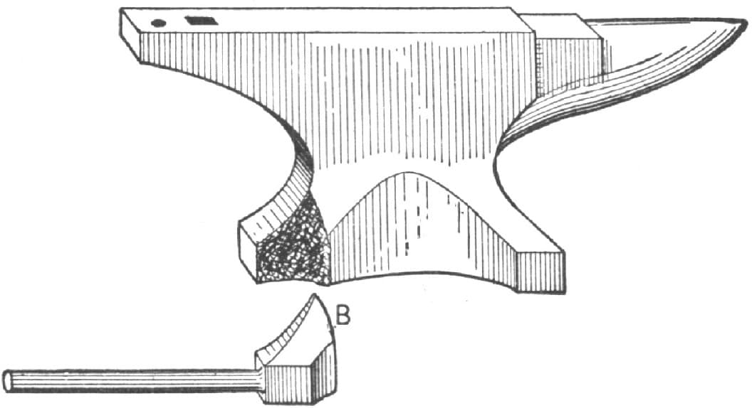
FIG. 60.—SHOWING HOW THE PIECE WAS WELDED ON AND SHAPED
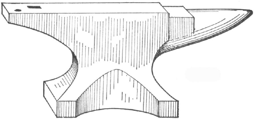
FIG. 61.—THE ANVIL AS MENDED
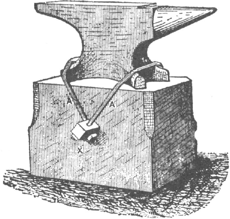
FIG. 62.—METHOD OF HOLDING AN ANVIL IN POSITION
FASTENING AN ANVIL IN POSITION.
I enclose you a drawing which shows a method for fastening an anvil down to the block that may be of interest to some of your readers. The fastening irons consist of two 3/8-inch round rods or clips that are bent around the anvil and block, as shown by A A in Fig. 62. At X there is a piece of 7/8-inch square iron run through the block. Four holes are drilled in this piece, the square iron through which the clips A A pass and into which they are fastened with nuts. The threads on the rods should be one inch longer on each end than they are needed, so that in case the anvil ever becomes loose it will be possible to draw it down by means of the nuts. Fig. 63 of the sketches shows the details of the parts. I think this fastening is one of the best that I have ever seen, and it is easy to make. It keeps the block from being split and driven full of spikes. I have never seen a better plan for holding an anvil than this. —By H. R. H.
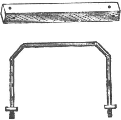
FIG. 63.—DETAILS OF DEVICE SHOWN IN FIG. 62
FASTENING AN ANVIL IN POSITION.
I enclose some rough sketches setting forth my ideas of the fastenings for an anvil. In the first place I do not have my anvil block any larger than the anvil base. I use braces as shown in the engraving, Fig. 64. The strap is made of 11/4 by 1/2-inch iron bent and flatways. Each end has a piece of 3/4-inch round iron welded on to it. Referring to the letters in the engraving, A represents the strap going around the foot of the anvil to receive B. On each side of the block on which the anvil rests a notch is cut to receive B. Referring to “H. R. H.’s” plan (see here), I would say that to me it appears that his fastenings would not amount to much unless their size was greatly increased. With this I think there is at least four times as much work to cut a square hole quite through the block as there is to have notches cut one on each side as indicated in my sketch.—By J. T. B.
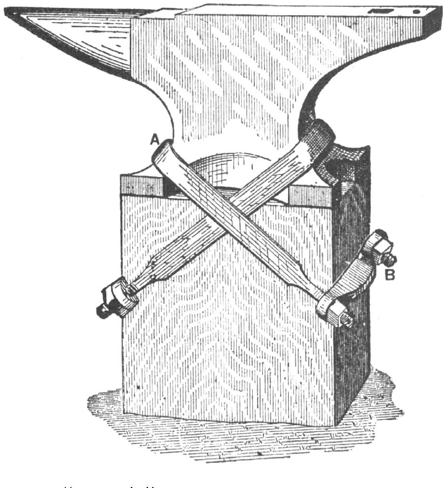
FIG. 64. “J. T. B.’S” METHODS OF FASTENING AN ANVIL
FASTENING ANVILS IN POSITION.
I enclose a sketch, Fig. 65, representing my own plan for holding an anvil in position. It serves the purpose well and is easily applied. The drawing so clearly shows the idea that very little explanation is necessary. By means of mortises in the sides of the block, nuts are inserted, into which bolts are screwed, as shown in the sketch. The short pieces, against which the heads of the bolts rest, are shaped in such a manner as to be driven by their outer ends into the block, thus holding them securely in place, and acting as a leverage in connection with the bolt for holding the anvil more securely. The depth at which the mortises in the sides of the blocks is made should be far enough from the top to give sufficient strength for clamping the anvil solidly in position. The braces at the side of the foot of the anvil need not project more than 1/2 or 3/4 of an inch from the anvil. Bolts 1/2 inch in diameter, or larger, should be used, according to the weight of the anvil to be held.
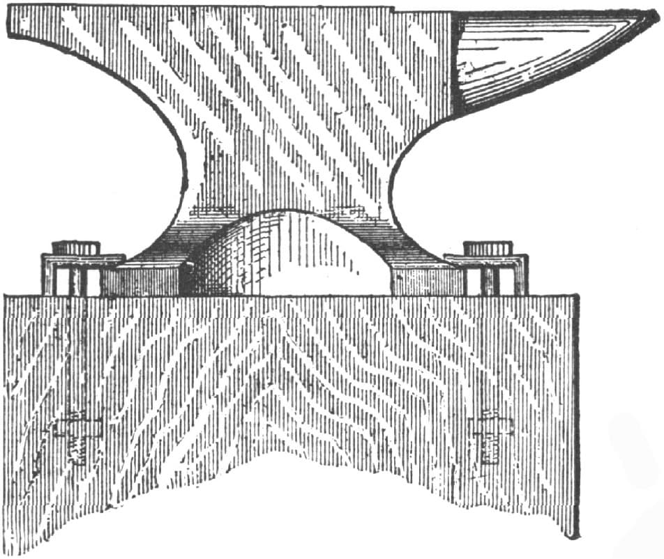
FIG. 65.—“M. R. R.’S” METHOD OF FASTENING AN ANVIL
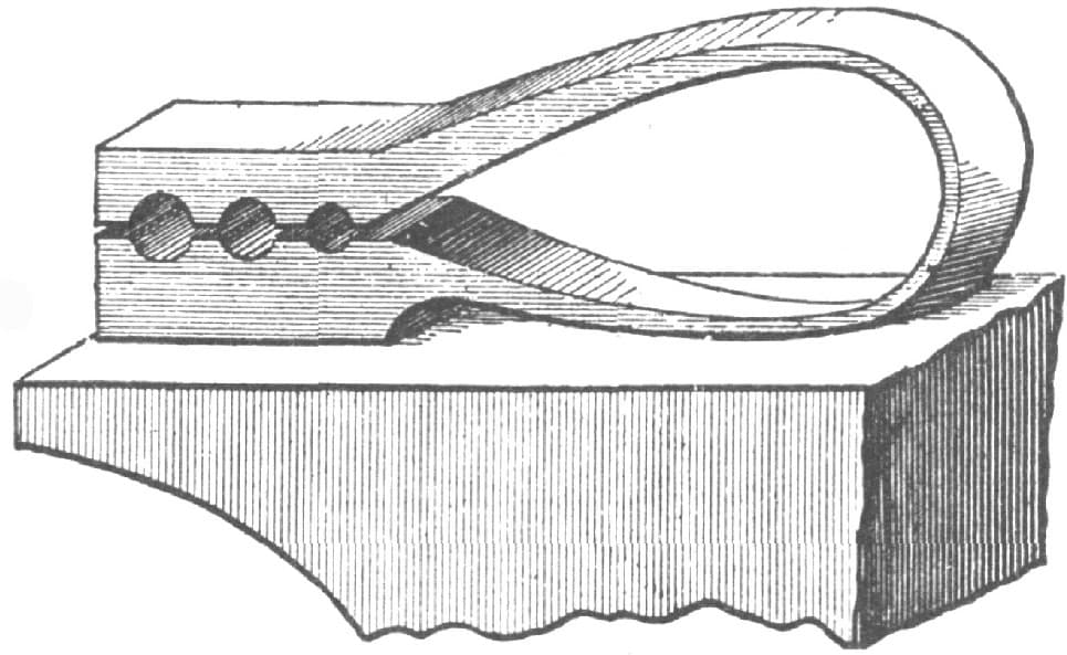
FIG. 66.—SELF-ACTING SWEDGE DESIGNED BY “E. M. B.”
A SELF-ACTING SWEDGE.
I send herewith a representation, Fig. 66, of a self-acting swedge for rounding up small work on the anvil without a striker or help. It sets into the anvil like an ordinary swedge, and the blacksmith strikes with his hand-hammer on top. It is made of iron, with a steel spring, which should be 1 to 11/2 inches wide by 1/4 inch thick.—By E. M. B.
MAKING A PUNCH.
I send a sketch, Fig. 67, of a punch which I made for my own use and find a very convenient tool. It can be constructed so as to punch to the center of any sheet. The part D, shown in the illustration, is dove-tailed, so that any size of die can be used. The punch is made of 3/4 or 7/8 inch square steel, with the point forged to the required size and with a small center to catch the center mark of the work. The machine is made to lie on the anvil, and part A is welded on to fit the square hole in the anvil. In using it, the punch is placed in the center mark of the work by hand, and the work is held firmly while the helper gives a good solid blow with the sledge. I have used one for four years. It will punch 7/16-inch round and square holes through 1/4 and 5/16-inch plow steel.—By H. S.
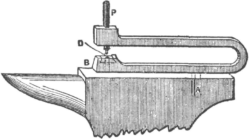
FIG. 67.—PUNCH MADE BY “H. S.”
MAKING AN ANVIL PUNCH.
I will try to describe an anvil punch that I made in my shop at an expense of two dollars only. I have a set of six, the sizes being 1/4, 3/8, 1/2, 5/8, 3/4 and 1 in., and I think every blacksmith should have a set of them. With the 1/4 in. and 3/8 in. size I can punch cold iron up to 5/16 in. thickness. With the 1/2, 5/8, 3/4, and 1 in. sizes I can punch 3/8 in. iron cold. I can punch steel saw blades as easily as band irons, and as the punch is used in the square hole in the anvil like any other anvil tool it does not take long to change from one size of punch to another. The tool is made as follows: I take a piece of Swedish iron 11/2 in. × 3/4 in. and 10 inches long, upset it a little on one end, then take a piece of good steel and cut off a square piece 11/2 in. × 11/2 in. and weld it firmly on the large end of the iron. Then I take a hand punch and punch a hole in the center of the steel, making the hole a little larger than that which the punch is to cut when finished. The punch should be driven from the iron side to make the hole largest on the bottom, so that the punchings will drop out. I then heat the other end, cut it half off 11/2 in. from the end, bend it over and weld it well, then take a square punch and punch and work out a 3/4 in. hole which must be perfectly true. The punch will then look as in Fig. 68. Then I take an iron the same size as the square hole in my anvil, and weld it on the bottom side of the punch 21/2 in. from the round hole in the punch, which is now like Fig. 69, and is ready to be filed off and dressed. Then I take a piece of 3/4 in. square cast steel, cut off 6 inches, draw it down and file one end so as to fit the round hole in the die of the punch. I make the top die of the 1/4 in. punch 5/16 in. long on the round part. For larger punches the dies should be larger. Fig. 70 represents the top die when finished. I then heat the punch, bend it so that the two holes will be in a line, fit in the top die and make sure that it goes perfectly true into the hole. Let it cool slowly, and when it is cool see that the face of the bottom die is all right, and that the die works straight and easily. Temper as you would for any tool intended to cut iron. Fig. 71 represents the punch when finished.—By N. C. M.

FIG. 68.—SHOWING THE PIECE AFTER WELDING, SHAPING AND PUNCHING

FIG. 69.—SHOWING THE PIECE READY FOR FILING, DRESSING AND BENDING

FIG. 70—THE TOP DIE OF THE PUNCH
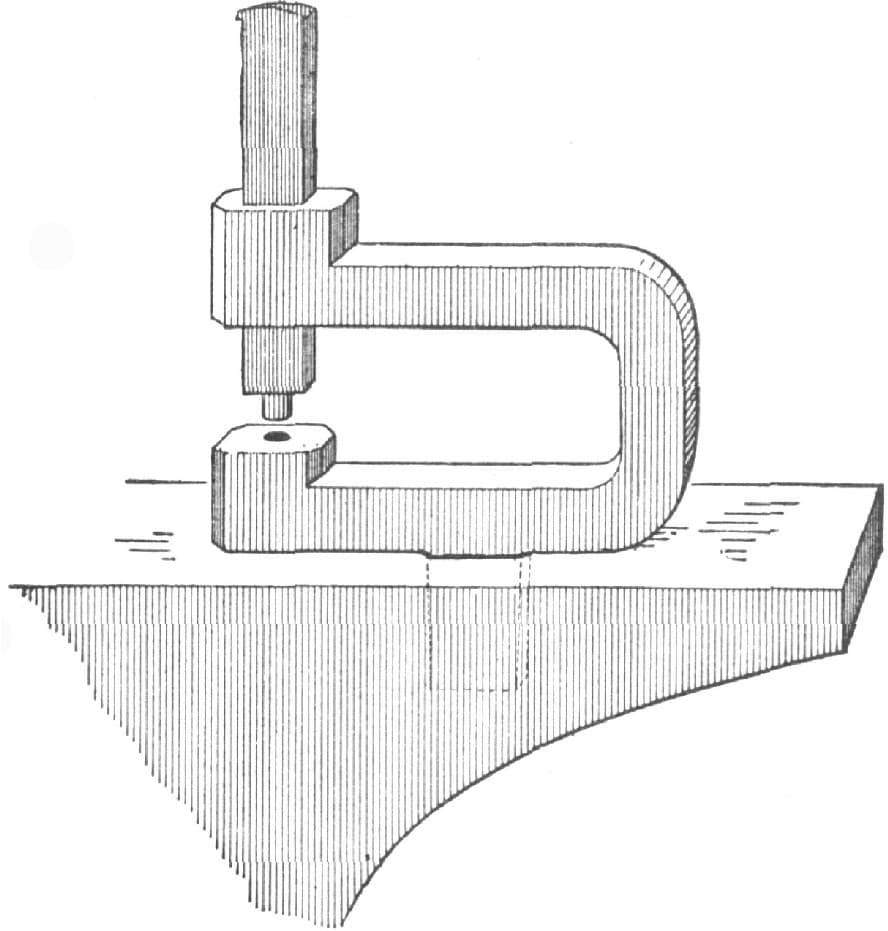
FIG. 71.—THE ANVIL PUNCH COMPLETED
FORGING A STEEL ANVIL.
I would like to say a few words about forging cast steel anvils. Fig. 72 of the engraving annexed shows the steel split and ready for the fullering. In Fig. 73 it is seen fullered and forming the outline of an anvil. The ends, when fullered to the proper shape, will form the face and bottom. In doing this it must be fullered on four sides and at the bottom, and drawn to the thickness proper for a face. After it is fullered it is brought back into place and trimmed to the right length, as indicated in the dotted lines of Fig. 73. Fig. 74 shows the job completed.
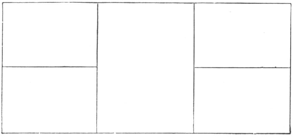
FIG. 72.—SHOWING THE PIECE SPLIT AND READY FOR FULLERING
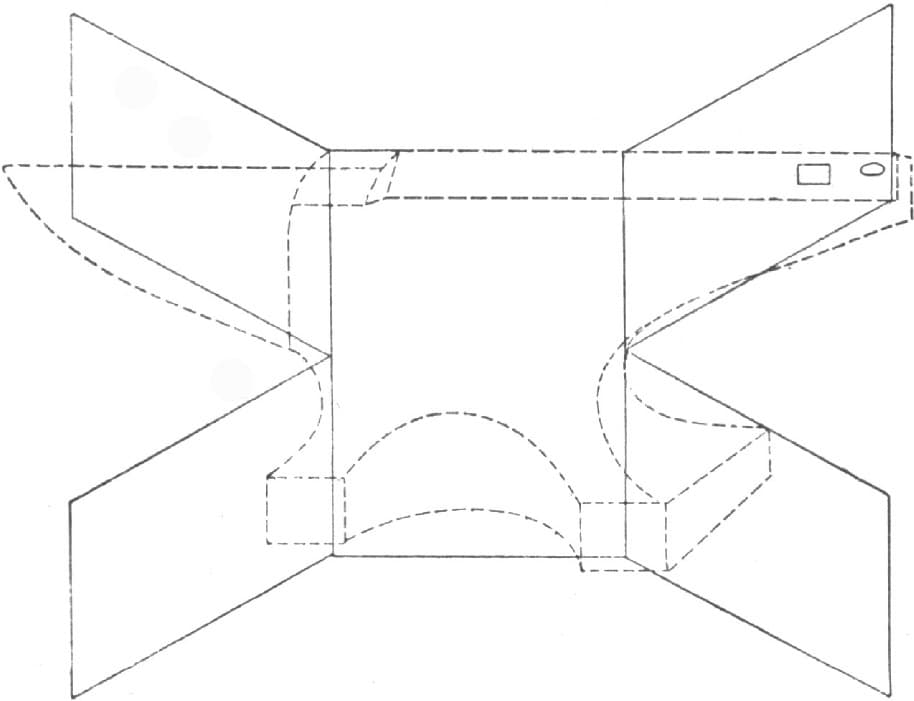
FIG. 73.—SHOWING THE STEEL FULLERED AND FORMED INTO THE OUTLINE OF AN ANVIL
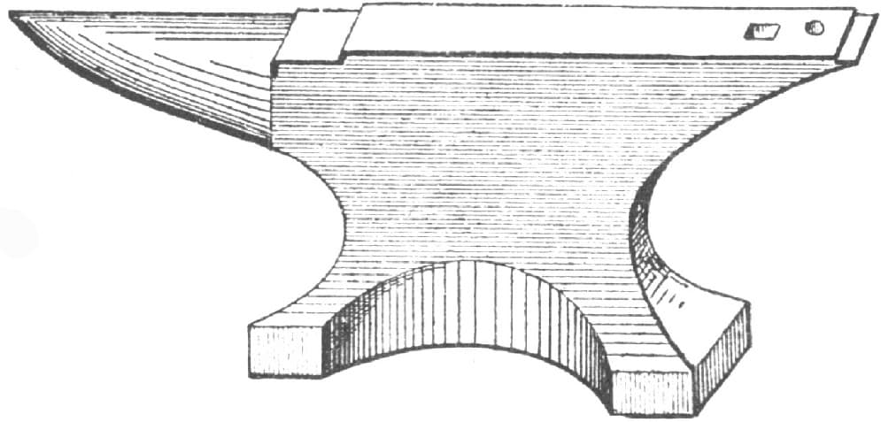
FIG. 74.—SHOWING THE FINISHED ANVIL
The steel should be chosen to correspond with the size of the anvil desired. I don’t think this method I have described would answer for a hundred-pound anvil, but it is convenient in making one from five to twenty pounds.—By C. E.
_____________
1 This article on the history, description, and manufacture of anvils will undoubtedly be found of interest to our readers. We have taken some pains to inform ourselves on this subject in consequence of some unfavorable comments which were made on an article on the same topic which appeared in the columns of The Blacksmith and Wheelwright a few years ago.—EDITOR.