CHAPTER V
BLACKSMITHS’ TOOLS
In this connection, tongs, hammers (not mentioned elsewhere) and various other tools commonly used by blacksmiths, will be illustrated and described.
THE PROPER SHAPE OF EYES FOR TOOL-HANDLES.
To properly fasten a handle in a tool is not so simple as it appears, and that is the reason that we so often see them improperly handled, as is evidenced by their so easily coming loose. I have a chipping-hammer that I once used for two consecutive years when working at the vise. It has been in intermittent use for some ten years since, and its handle shows no signs of coming loose, for the simple reason that it was properly put in in the first place.
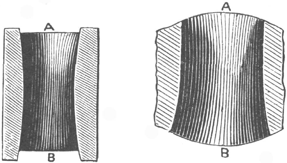
FIGS. 75 AND 76.—CORRECT SHAPE OF EYE FOR TOOL-HANDLE
The correct shape for an eye to receive a tool-handle is shown in Figs. 75 and 76, which are sectional views. A is the top and B the bottom of the tool. Two sides of the hole, it will be observed in Fig. 75, are rounded out from the center towards each end. The other two sides are parallel from the top to the center, as shown in Fig. 76, while the bottom half of the hole is rounded out as before. The shape thus obtained may be clearly understood from Fig. 77, which is a view of the top, or face A, and Fig. 78, which is a view of the bottom, or face B. The handle is fitted a driving fit to the eye, and is shaped as shown in Figs. 79 and 80, which are side and edge views. From C to D, the handle fills the eye, but from D to E it fills the eye lengthways only of the oval. A saw-slot to receive a wedge, is cut in the handle, as shown in Fig. 80. The wedge is best made of soft wood, which will compress and conform itself to the shape of the slot. To drive the handle into the eye, preparatory to wedging it permanently, it should be placed in the eye, held vertically, with the tool head hanging downward, and the upper end struck with a mallet or hammer, which is better than resting the tool-head on a block. The wedge should be made longer than will fill the slot, so that its upper end may project well, and the protruding part, which may split or bulge in the driving, may be cut off after the wedge is driven home.
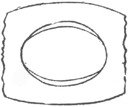
FIG. 77.—TOP VIEW
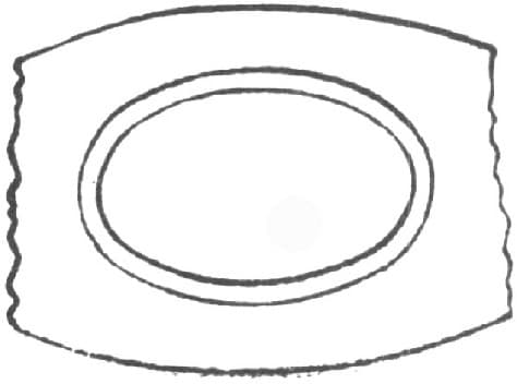
FIG. 78.—BOTTOM VIEW
FIG. 79.—SHAPE OF HANDLE
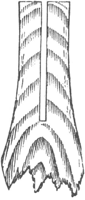
FIG. 80.—SHAPE OF HANDLE
ANOTHER VIEW
The wedge should be driven first with a mallet and finally with a hammer. After a very few blows on the wedge, the tool should be suspended by the handle and the end of the latter struck to keep the handle firmly home in the eye. This is necessary, because driving the wedge in is apt to drive the handle partly out of the eye.
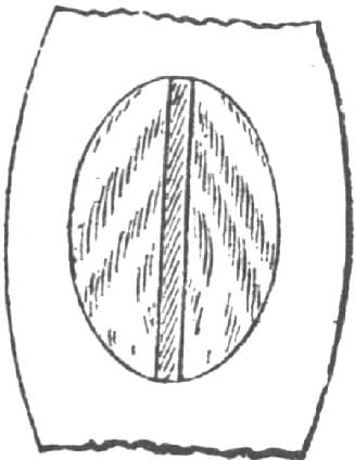
FIG. 81.—SHAPE OF WEDGE
The width of the wedge should equal the full length of the oval at the top of the eye, so that one wedge will spread the handle out to completely fill the eye, as shown in Fig. 81. Metal wedges are not so good as wooden ones, because they have less elasticity and do not so readily conform to the shape of the saw-slot, for which reason they are more apt to come loose. The taper on the wedge should be regulated to suit the amount of taper in the eye, while the thickness of the wedge should be sufficiently in excess of the width of the saw-cut, added to the taper in the eye, to avoid all danger of the end of the wedge meeting the bottom of the saw-slot.
By this method the tool handle is locked to the tool eye by being spread at each end of the same. If the top end of the tool eye were rounded out both ways of the oval, two wedges would be required to spread the handle end to fit the eye, one wedge standing at a right angle to the other. In this case one wedge must be of wood and one of metal, the one standing across the width of the oval usually being the metal one. The thin edge of the metal wedge is by some twisted, as shown by Fig. 82, which causes the wedge to become somewhat locked when driven in.
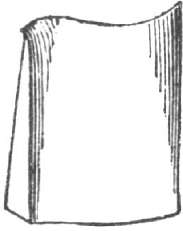
FIG. 82.—SHAPE OF METAL WEDGE
In fitting the handle, care must be taken that its oval is made to stand true with the oval on the tool eye. Especially is this necessary in the case of a hammer. Suppose, for example, that in Fig. 83 the length of the oval of the handle lies in the plane A B, while that of the eye lies in the plane C D; then the face of the hammer will meet the work on one side, and the hammer will wear on one side, as shown in the figure at E. If, however, the eye is not true in the hammer, the handle must be fitted true to the body of the hammer; that is to say, to the line C D. The reason for this is that the hand naturally grasps the handle in such a manner that the length of the oval of the handle lies in the plane of the line of motion when striking a blow, and it is obvious that to strike a fair blow the length of the hammer should also stand in the plane of motion.
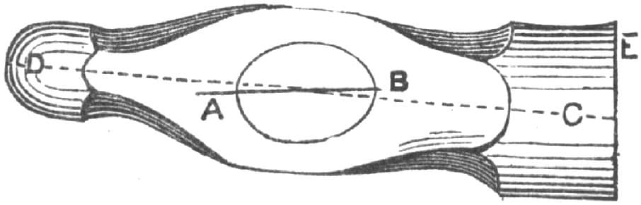
FIG. 83.—FITTING THE HANDLE
The handle should also stand at a right angle to the plane of the length of the hammer head, viewed from the side elevation, as shown in Fig. 84, in which the dotted line is the plane of the hammer’s length, while B represents a line at a right angle to A, and should, therefore, represent the axial line of the hammer handle. But suppose the handle stood as denoted by the dotted line C, then the face of the hammer would wear to one side, as shown in the figure at D.—By JOSHUA ROSE, M.E.
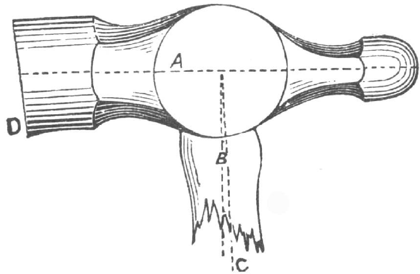
FIG. 84.—HANDLE AT RIGHT ANGLE TO PLANE OF LENGTH OF HAMMER HEAD
BLACKSMITHS’ TONGS AND TOOLS.
[Prize Competition Essay.]
My knowledge of tools is confined to the class known as the machine blacksmith’s tools. But these may be of interest to the horseshoer and carriage ironer, and their tools may interest the machine blacksmith.
The list of tools would not be complete unless the smith’s hand hammer was mentioned, and as a rule the smith takes great pride in it. These hammers are of the class known as the ball pane, as shown in Fig. 85 of the accompanying illustrations. The weight of the hammer is according to the taste of the man who uses it, but the average weight is about 2 lbs. 4 ozs. Fig. 86 represents a pair of double calipers, one side of which is used for taking the width and the other side for the thickness when working a piece of iron. Fig. 87 is a pair of single calipers for general use and needs no explanation. Fig. 88 is a pair of common dividers which are used for describing the circles on pieces that need to be cut round, and they can be used as a gauge in welding up pieces to a given length. Fig. 89 is a T-square, which is as useful a tool as ever got into a shop for squaring up work with. The short leg can be dropped into a hole while squaring the face with the T, or it can be used for a handle while using the back to square up flat pieces. These tools should belong to every smith and be his private property. The ordinary 2-ft. square which every smith ought to be provided with is usually supplied by the owner of the shop. A good 2-ft. brass rule is something that every smith ought to have.
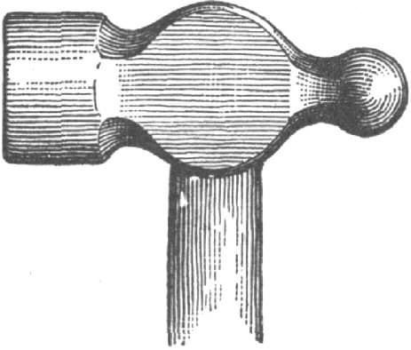
FIG. 85.—THE BALL PANE HAMMER
FIG. 86.—THE DOUBLE CALIPERS
Opinions differ as regards the fire and anvil of the machine smith. But a neat outfit is a portable forge made for general work, and a 300-lb. Eagle anvil with all the sharp corners ground off, and made a little more rounding next to the beak iron than on the other end. The sledges usually found to be most convenient are the straight pane pattern, Fig. 90, of 8 lbs., 12 lbs., and 16 lbs. weight, the 12-lb. sledge being for general use, and the others for light or heavy work as occasion demands.
In addition to these, each fire usually has what is called a backing hammer, which is of the same style as the smith’s hammer, but weighing only 31/2 lbs. This is used to assist the smith in backing up a piece of iron when scarfing for welding, and for finishing up work where the sledges are too heavy.
FIG. 87.—THE SINGLE CALIPERS
Tongs rank among one of the most important things in a blacksmith’s outfit. Fig. 91 represents the pick-up tongs, which are especially the helper’s tongs and are used to pick up tools and small pieces generally.
Fig. 92 represents a pair of ordinary flat tongs for holding flat iron, and they need little explanation. Fig. 93 represents a pair of box tongs for holding square or flat iron, the lip on each side preventing the iron from slipping around. Figs. 94 and 95 show a pair of tongs, one pair of which can be made to fit several sizes by making the box piece to fit the size of iron to be used. Fig. 94 shows the pieces apart, and Fig. 95 shows how they are used. Fig. 96 represents a pair of round bit tongs for holding round iron. Fig. 97 shows a pair of hollow bits for holding round iron, and for pieces having a larger end than the body, such as bolts, etc. Fig. 98 represents a pair of square, hollow bits that answer the same purpose as the bits shown in Fig. 97, except that the square bits will hold square or round iron.
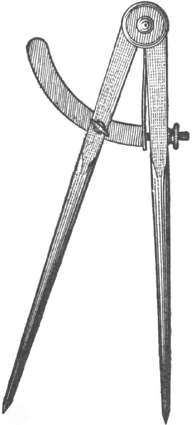
FIG. 88.—THE DIVIDERS
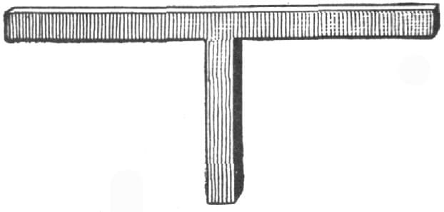
FIG. 89.—THE T-SQUARE
Fig. 99 represents a pair of flat tongs for holding large pieces, the diamond-shaped crease in the bits making them handy for holding large pieces of square or round iron. Fig. 100 shows a pair of pincer tongs, useful for many purposes. Holding work that has a round piece raised off the main body, they can be made still more useful by cutting out the tops of the bits, as shown in the figure. Fig. 101 shows tongs for holding work where the iron is bent flatwise. The tongs shown in Fig. 102 are useful, for they can be made to suit any size. Those shown in Fig. 103 are for work that cannot be held in an ordinary pair of flat tongs on account of the bits not being long enough. The bits are bent at right angles, so that the work will pass by the joints. Fig. 104 shows a pair of the same style of tongs with the bits bent to hold round iron.
FIG. 90.—THE STRAIGHT PANE SLEDGE
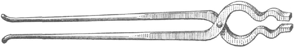
FIG. 91.—THE PICK-UP TONGS
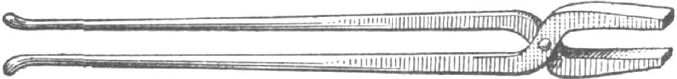
FIG. 92.—THE FLAT TONGS
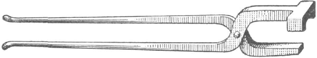
FIG. 93.—THE BOX TONGS
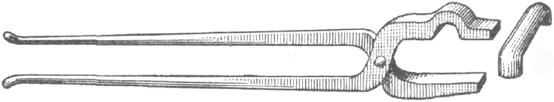
FIG. 94.—THE TONGS WITH BOX PIECE
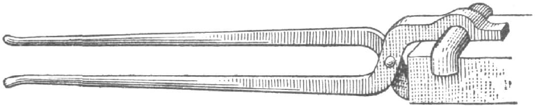
FIG. 95.—SHOWING HOW THE TONGS AND BOX PIECES ARE USED
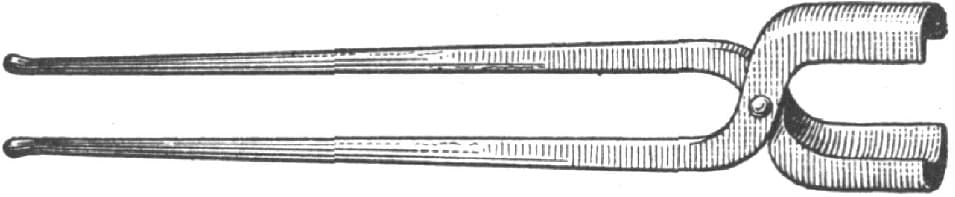
FIG. 96.—ROUND-BIT TONGS
Another style of crooked-bit tongs is shown in Fig. 105, in which the bits are bent down instead of sidewise as in Fig. 103. They are useful for handling rings of flat iron and for holding flat iron while bending flatways. For holding work while the iron is being bent on edge, the tongs shown in Fig. 106 are good, the lip bent on one of the bits preventing the iron from pulling out of the tongs. Fig. 107 represents a pair of tongs for holding chisels while sharpening them, or for holding any such tools while they are being repaired. For making bolts out of round iron the tongs as shown in Fig. 108 will beat any I ever saw. They have the ordinary hollow bit, with a piece cut out of each bit crosswise to hold the round iron in upsetting. The swell in the bits allows the head to be taken in while straightening the other end. All of the foregoing named tongs can be made of any size, large or small; and the smith shop that has all of these different shapes is pretty well equipped.
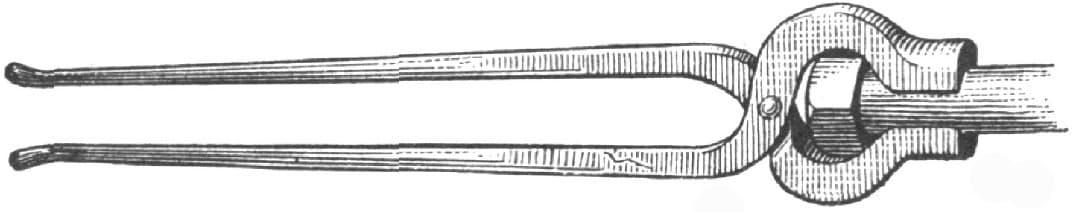
FIG. 97.—HOLLOW-BIT TONGS
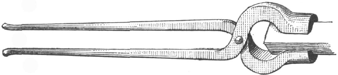
FIG. 98.—TONGS WITH SQUARE, HOLLOW BITS
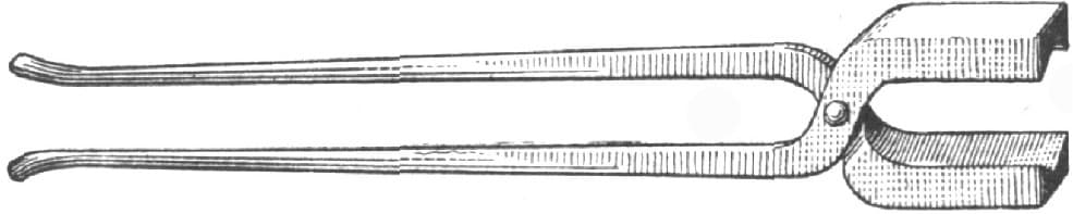
FIG. 99—FLAT TONGS FOR HOLDING LARGE PIECES
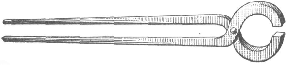
FIG. 100. PINCER TONGS
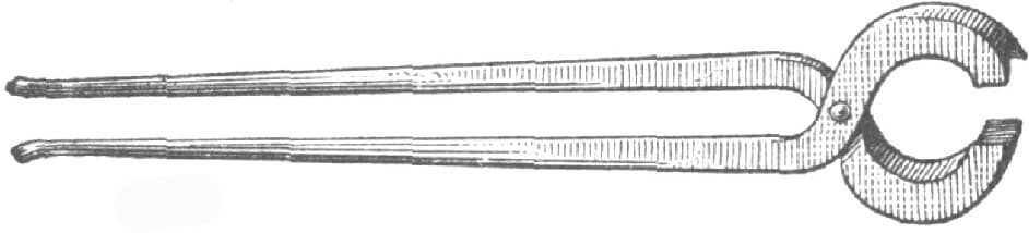
FIG. 101.—TONGS FOR BENDING IRON FLATWISE
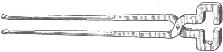
FIG. 102.—TONGS FOR HOLDING PIECES OF DIFFERENT SIZES
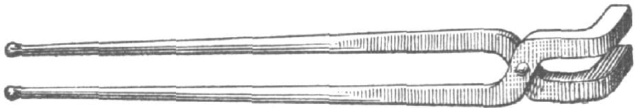
FIG. 103.—TONGS WITH BENT BITS
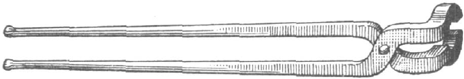
FIG. 104—TONGS WITH BENT BITS FOR HOLDING ROUND IRON
Next in importance are the chisels, punches and tools for the anvil. Fig. 109 represents the ordinary hot chisel, or hot-set, as it is known in some localities. The ordinary cold chisel is shown in Fig. 110. The hardy for the anvil is so well known as to need no illustration. The gouge chisel, as shown in Fig. 111, is for cutting off round corners at one operation. It can be ground inside or out, thus making an inside or outside tool. The round punch shown in Fig. 112 needs no explanation of its uses, but it can be used for a gouge, where a good stiff one is required, by grinding it off bevel. In some work a square chisel comes very handy; one made as shown in Fig. 113 is very good. The square punch shown in Fig. 114 can also be ground bevel and used for a square or corner chisel. The long or eye punch is shown in Fig. 115. For countersinking holes and such work the bob punch or countersink, as shown in Fig. 116, is about what is needed, while for cupping or rounding off the heads of bolts and nuts, and for similar work, the cupping tool as shown in Fig. 117 is used.
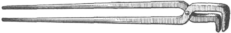
FIG. 105.—CROOKED-BIT TONGS
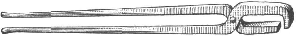
FIG. 106.—TONGS USED IN BENDING IRON ON THE EDGE
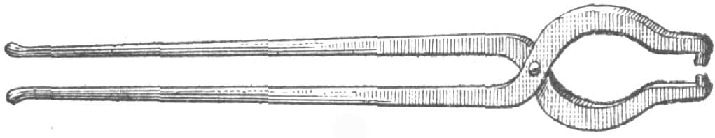
FIG. 107.—TONGS USED IN SHARPENING CHISELS
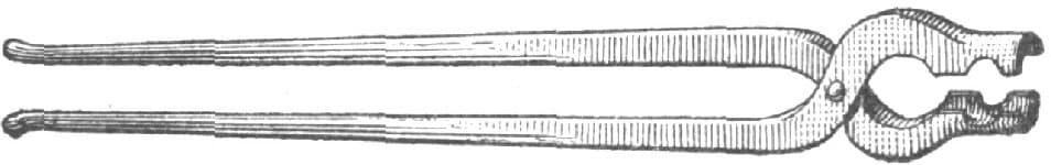
FIG. 108.—TONGS USED IN MAKING BOLTS OF ROUND IRON
A tool of this kind comes handy many a time if made to fit the hardy hole.
For setting down work and getting into small places in which the latter cannot be used we have the set hammer shown in Fig. 118. It is made with square edges, and when made with the edges rounded off it is called a round-edge set hammer. These hammers are also made with the face cut off at an angle, in order to get down into corners and to settle work down very square. Fig. 119 represents the ordinary top swage for rounding up work, and Fig. 120 shows the bottom swage. Every smith knows the value of a good set of swages. They can be made long, that is, the full width of the anvil, or they can be made very short: the short ones take the name of necking swages. Fig. 121 represents a side swage, the eye being punched in opposite from the ordinary swage. These are used for rounding off the ends of flat pieces, being handier than the ordinary swage. Fig. 122 shows an anvil side swage or bottom swage, a swage being made on the end to overhang the edge of the anvil, so that bent pieces that need to be swaged can be dropped over the edge of the anvil and swaged up without much trouble.
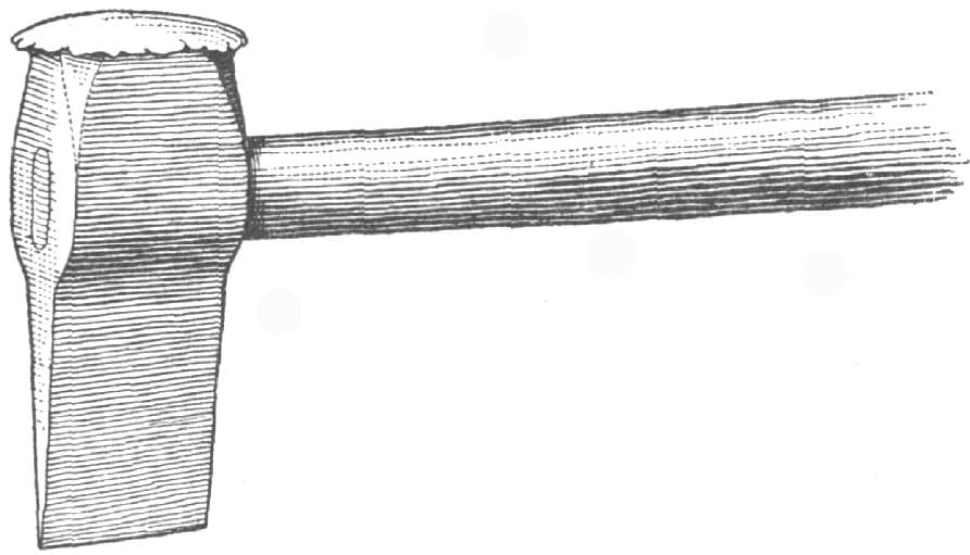
FIG. 109.—THE HOT CHISEL
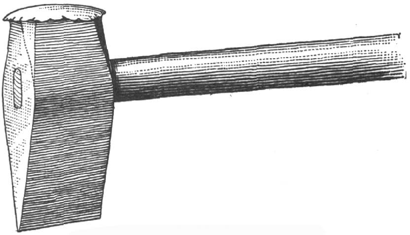
FIG. 110.—THE COLD CHISEL
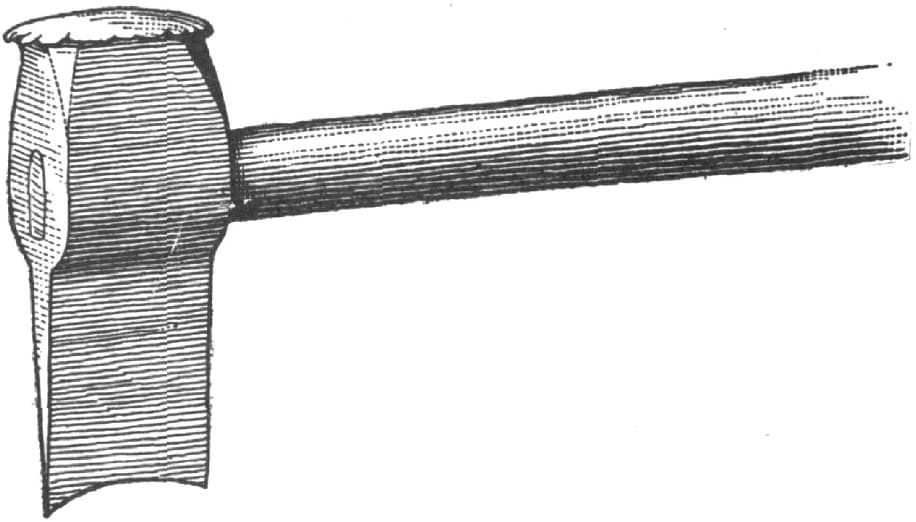
FIG. 111.—THE GOUGE CHISEL
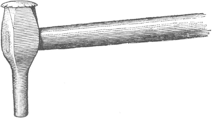
FIG. 112.—THE ROUND PUNCH
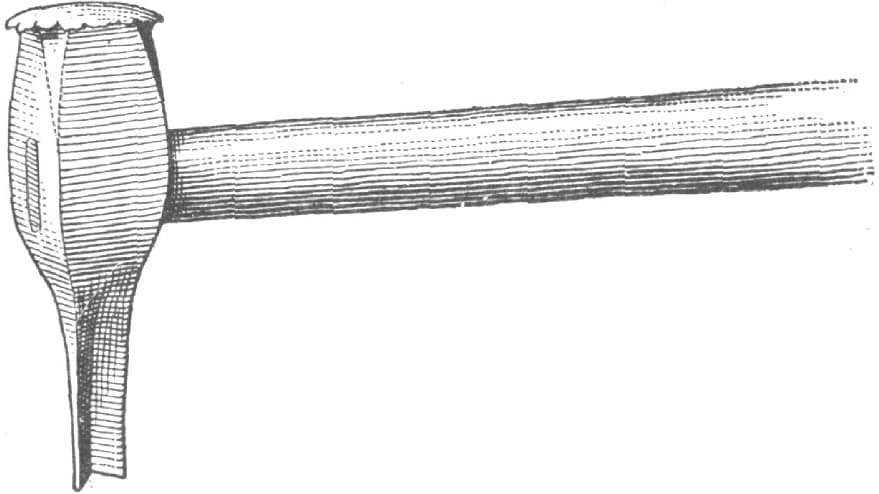
FIG. 113.—THE SQUARE CHISEL
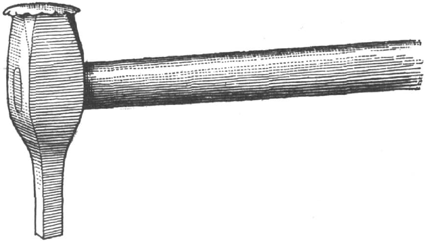
FIG. 114.—THE SQUARE PUNCH
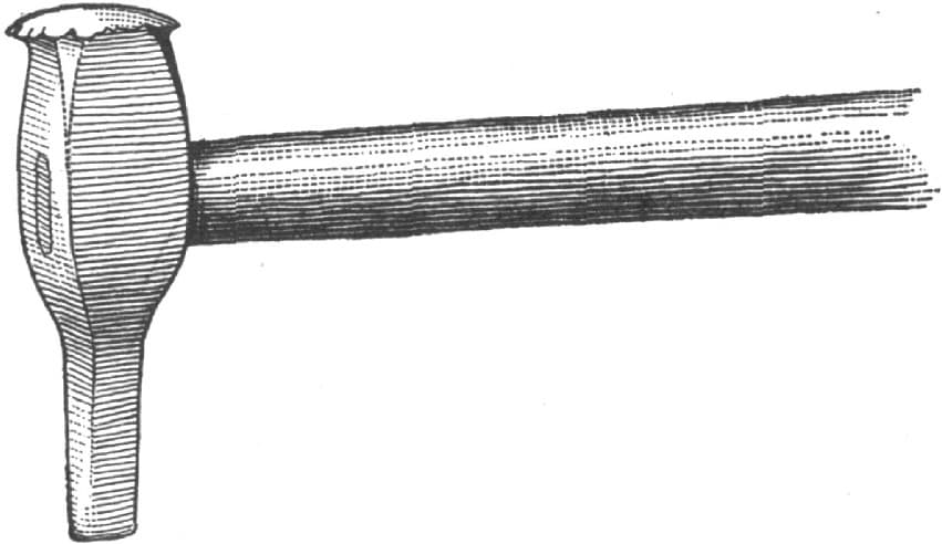
FIG. 115.—THE LONG OR EYE PUNCH
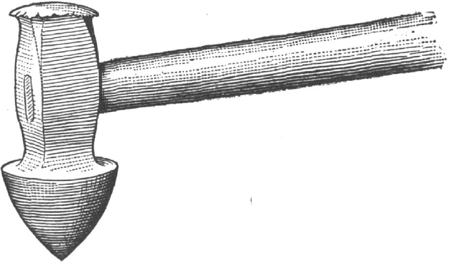
FIG. 116.—THE BOB PUNCH OR COUNTERSINK
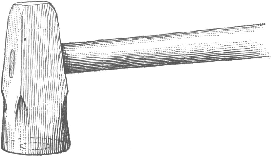
FIG. 117.—THE CUPPING TOOL
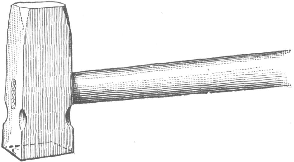
FIG. 118.—THE SET HAMMER
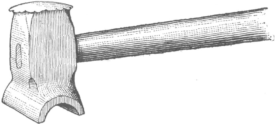
FIG. 119.—THE TOP SWAGE
The top and bottom fullers shown in Figs. 123 and 124 are familiar to every smith. The horn on the bottom fuller is to prevent the piece to be fullered from being knocked off the tool at every blow of the striker’s sledge. For smoothing up work the smith has the flatter, Fig. 125, which takes out the lumps and uneven places and gives the work a finished appearance.
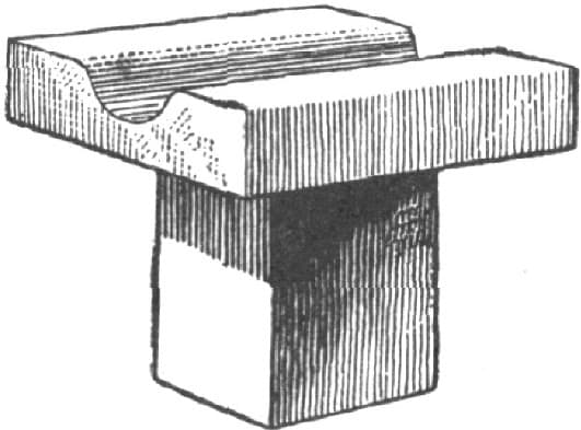
FIG. 120.—THE BOTTOM SWAGE
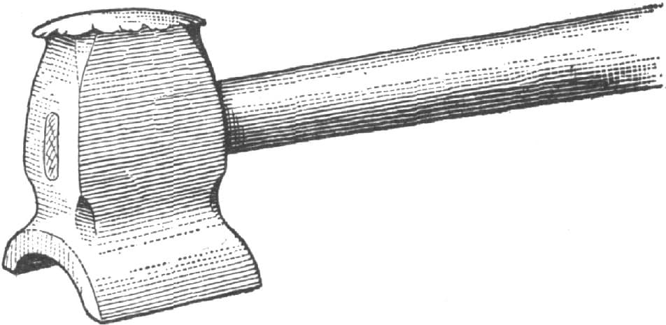
FIG. 121.—THE SIDE SWAGE
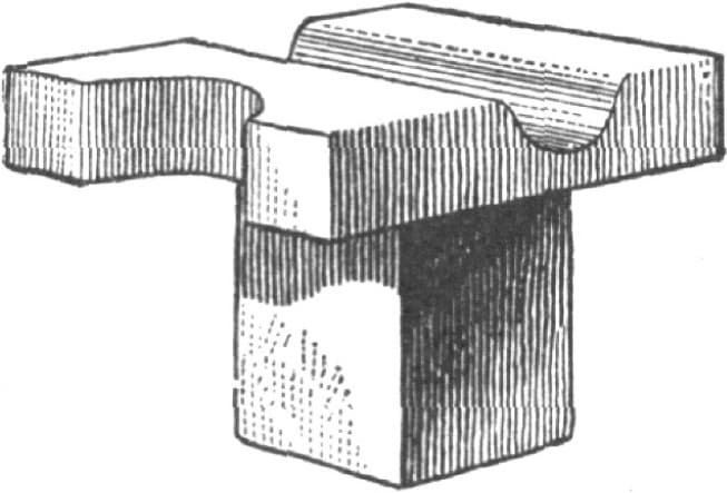
FIG. 122.—THE ANVIL SIDE OR BOTTOM SWAGE
Sometimes a piece is so bent that a flatter cannot be used, and the smith then falls back on his foot tool, shown in Fig. 126. The foot goes in on the work, and the head outside. A glance at the sketch will show how useful it can be in almost any smith’s shop.
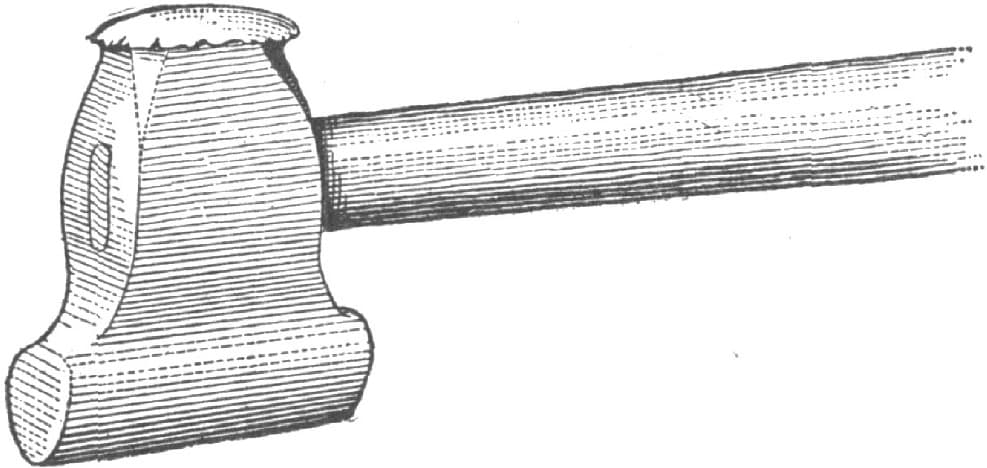
FIG. 123.—THE TOP FULLER
It sometimes happens that it is necessary to leave round corners on a piece of work, and in finishing it up the ordinary flatter would mark it and spoil its appearance The smith then makes use of the round-edge flatter shown in Fig. 127. This tool is also useful in bending flat iron, the round edge preventing galling.
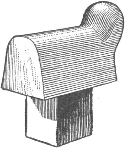
FIG. 124.—THE BOTTOM FULLER
FIG. 125.—THE FLATTER
The smith sometimes has a lot of small rings to make, or to work out holes which are too small for the beak iron. For such work a small cone to fit the anvil, as shown in Fig. 128, is very useful. Or he may have some collars to weld on round iron, and after making one or two he wishes he had a quicker way and one that would make them all look alike. He bethinks himself of the collar swages he heard that “Tramp Blacksmith” talk about, so he makes a pair of collar swages as shown in Fig. 129. Only the bottom swage is shown, as the impression in the top is like the bottom. After making three or four pieces he “gets the hang” of the tools, and the work goes merrily on, each piece looking like the other.
FIG. 126.—THE FOOT TOOL
FIG. 127.—THE ROUND-EDGE FLATTER
He sometimes has to make bends in his work, and then the fork shown in Fig. 130 comes in very handy. I have seen this tool used for making hooks on the end of long rods, one fork being used to press against and the other to bend the hook around. Fig. 131 represents a tool for bending flat pieces at right angles and making T-pieces.
FIG. 128.—THE ANVIL CONF
FIG. 129.—THE COLLAR SWAGE
The smith drops the iron in the slot, and he can bend or twist it anyway he likes.
Sometimes work needs fullering, but is so offset that one end rests on the anvil and the other towers away above the fuller. The smith then uses the fuller shown in Fig. 132, the outside edge of the fuller being brought flush with the side of the anvil, thus enabling the smith to drop his work down the side of the anvil and proceed as with an ordinary fuller.
FIG. 130.—A FORK USED IN BENDING
FIG. 131.—A TOOL FOR BENDING FLAT PIECES AND MAKING T PIECES
In most machine blacksmith shops they have more or less bolts and nuts to make. Fig. 133 represents the ordinary nut swage used for swaging nuts or finishing up the heads of hexagon bolts. Fig. 134 shows a better tool for making bolts. Only one-half is sunk hexagon, the other half being the ordinary bottom round swage, so, that in making a bolt as it is turned around in the swage the shank of the bolt is brought central with the head. Smiths who have trouble in getting the head of the bolt central with the shank, will, by using this tool, be able to make a good bolt. The tool shown in Fig. 135 has grooves cut in until they meet at the bottom, so that many different-sized heads or nuts can be made in it, the small ones going far down and the larger ones filling it up. In Fig. 136 is shown the ordinary heading tool. Fig. 137 represents a nut mandrel in which the shank is made smaller than the body part, in order to drive it through the nut.
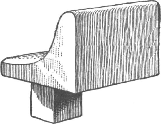
FIG. 132.—A FULLER FOR OFFSET WORK
FIG. 133.—A NUT SWAGE
FIG. 134.—A TOOL FOR MAKING BOLTS
FIG. 135.—A TOOL FOR MAKING HEADS OR NUTS OF VARIOUS SIZES
Fig. 138 shows a bridge or saddle used for drawing out forked pieces, making open-end wrenches and similar work.
I have not attempted to describe the hand punches, but, as is known, hand punches, round, flat and hexagonal, are very useful in the smith’s shop. Pins for driving through holes to expand them are so well known to all smiths that I do not deem it necessary to take up space in describing them. The tools that I have attempted to describe are in every-day use, and I think they form altogether a good outfit for a machine blacksmith shop.—By WARDLEY LANE.
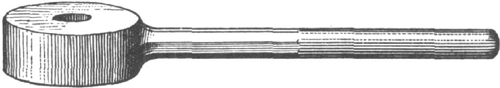
FIG. 136.—THE HEADING TOOL

FIG. 137.—A NUT MANDREL
PROPER SHAPE FOR BLACKSMITHS’ TONGS
The proper shape for blacksmiths’ tongs depends upon whether they are to be used upon work of a uniform size and shape or upon general work. In the first case the tongs may be formed to exactly suit the special work. In the second case they must be formed to suit as wide a range of work as convenient.
Suppose, for example, the tongs are for use on a special size and shape of metal only. Then they should be formed as in Fig. 139, the jaws gripping the work evenly all along, and being straight along the gripping surface. The ends A B are curved so that the ring C shall not slide back and come off. It will readily be perceived, however, that if these tongs were put upon a piece of work of greater thickness, they would grip it at the inner end only, as in Fig. 140, and it would be impossible to hold the work steady. The end of the work, W, would act as a pivot, and the part on the anvil would move about. It is better, therefore, for general work, to form the jaws as shown in Fig. 141, putting the work sufficiently within the jaws to meet them at the curve in the jaw, when the end B also grips the work. By putting the work more or less within the tongs, according to its thickness, contact at the end of the work as at A, and at the point of the tongs as at B, may be secured in one pair of tongs over a wider range of thickness of work than would otherwise be the case. This applies to tongs for round or other work equally as well as to flat or square work.
FIG. 138.—SADDLE USED FOR DRAWING OUT FORKED PIECES
FIG. 139.—PROPER SHAPE OF TONGS FOR SPECIAL WORK
FIG. 140.—IMPROPER SHAPE
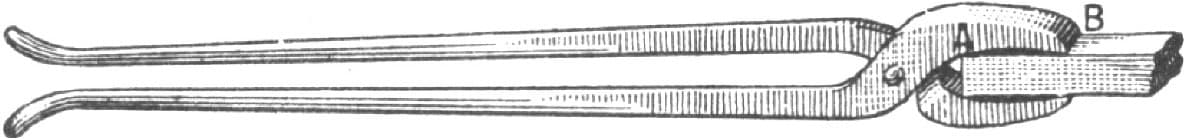
FIG. 141.—PROPER SHAPE OF JAWS FOR GENERAL USE
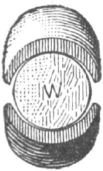
FIG. 142.—SHAPE OF TONG JAWS FOR ROUND WORK
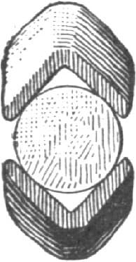
FIG. 143.—SHAPE OF SQUARE TONG JAWS FOR ROUND WORK
For round work, the curve in the tong jaws should always be less than that of the work, as shown in the end view, Fig. 142, in which W represents the work or if round work be held in square tongs, it should touch the sides of the square as shown in Fig. 143, and in all cases there should be a little spring to the jaws of the tongs, to cause them to conform somewhat to the shape of the iron. This not only causes the tongs to hold the work firmer, but it also increases the range of the capacity of the tongs. Thus in the shape of tongs shown in Fig. 144, the bow of the jaws would give them a certain amount of spring, that would enable them to conform to the shape of the work more readily than those shown in Fig. 139, while at the same time it affords room for a protection head or lug. For short and headed work, such as bolts, the form shown in Fig. 145 is the best, the thickness at the points always being reduced to give some elasticity, and in this case to envelope less of the length of the bolt also.
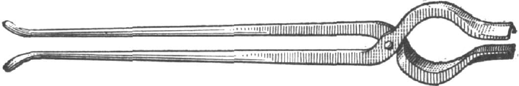
FIG. 144.—PROPER BOW OF JAWS
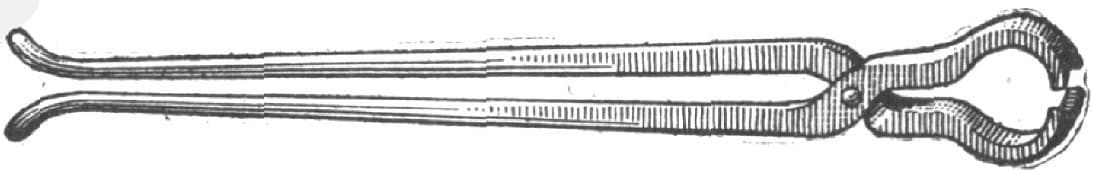
FIG. 145.—PROPER SHAPE FOR BOLTS
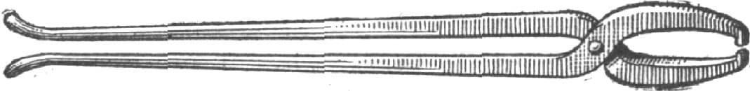
FIG. 146.—SHAPE FOR IRREGULAR SHAPED WORK
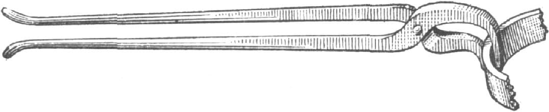
FIG. 147.—HOOP TONGS
For holding awkward shaped work containing an eye, the form shown in Fig. 146 is best, the taper in this case running both ways, as shown, to give increased elasticity. The same rule also applies to the hoop tongs shown in Fig. 147.
Perhaps the best example of the advantage of having a certain amount of spring, or give, in the jaws of tongs is shown in the pick up tongs in Fig. 148, the curves giving the jaws so much elasticity that the points at A will first grip the work, and as the tongs are tightened the curves at B will, from the spring of the jaws, also come in contact, thus gripping the work in two places, and prevent it from moving on a single point of contact on each jaw as a pivot.
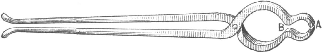
FIG. 148.—PICK-UP TONGS
It follows from this that all tongs should first meet the work at the point as in Fig. 149, and spring down to meet it at the back end as the tongs tighten upon the work, and it follows also that the thickness of the jaws should always be well tapered, and not parallel, as many unthinking men are apt to make them.—By J. R.
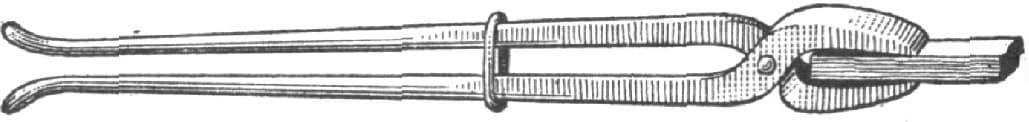
FIG. 149.—PROPER SHAPE
BLACKSMITHS’ TOOLS.
[Prize Essay.]
In the accompanying illustrations of blacksmiths’ tools, No. 1, in Fig. 150, represents a stay that goes from the axle to the perch in buggy gear. The pieces A and B are made from 7/16-inch round iron and C is 1/2 inch. No. 2, in Fig. 150, is the bottom tool used in forming the offset, and No. 3, Fig, 150, is the top tool.
To make the stay, cut off two pieces of 7/16-inch round Lowmoor iron of the length required for A and B, No. 1, Fig. 150, cutting B about 3 inches longer than it is to be when finished. Then cut a piece of 1/2-inch iron for C, Fig. 150. Next heat the ends of A and C, upset and weld, leaving it a little larger than 1/2 inch at the weld. Next heat B at the end and double it back about 21/2 inches, weld and upset a little to make up for loss in welding. Now draw out as shown in A, Fig. 151, bend as in Fig. 152, and insert the fuller at A. Then heat the end A, Fig. 152, and with a thin splitting chisel split and scarf. Then place it on the bar marked A and C, Fig. 153, put it in the fire, take a nice welding heat, and with a light hammer weld it lightly working in the corners of the scarf. Then return it immediately to the fire, get a good soft heat, and place it in the tool No. 2, Fig. 150, with the tool No. 3, Fig. 150, on top. Let the helper give it three or four sharp blows and the job is finished. If there should be any surplus stock it will be squeezed out between the tools and can be easily removed with a sharp chisel.
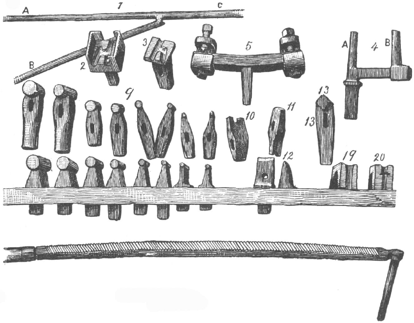
FIG. 150
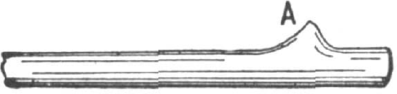
FIG. 151.—SHOWING HOW THE PIECE IS DRAWN OUT
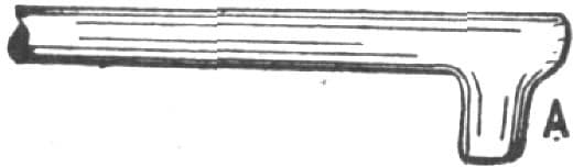
FIG. 152.—SHOWING HOW THE PIECE IS BENT
The reader will notice that there is a box in the tool No. 2, Fig. 150, which serves to bring No. 3 in the right place every time. If the tools are made properly the job will look like a drop-forging without any sign of a weld. Two offsets for gears can be made in this way in fifteen minutes by any good mechanic.
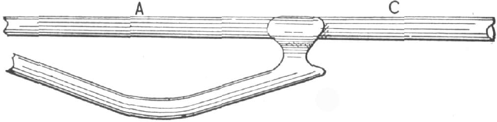
FIG. 153.—SHOWING HOW THE PIECES ARE JOINED AND WELDED IN MAKING AN OFFSET
No. 4, Fig. 150, is a bending crotch. The prongs A and B are made oval, and B is adjustable to any size needed. This tool is made of cast steel throughout. To make it take a piece of cast steel 11/2 inches square, fuller and draw down the end to fit the square hole of the anvil, then flatten the top and split; next bend C at right angle to A, and finish to 7/8 inch square. Then draw out A to about an inch oval on the angle, fuller and draw out the end B, cut off and punch the square hole, and work up the socket to 7/8 inch square, and it is ready for use. Then make a top wrench as shown at No. 57, Fig. 182. I like to have two top wrenches, one for light and one for heavy work.
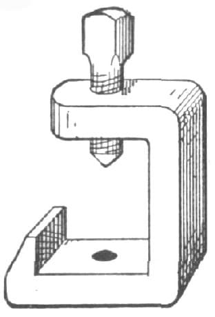
FIG. 154.—THE CLIP USED ON THE TIRE-SETTER MARKED NO. 5, IN FIG. 150
No. 5, Fig. 150, is a home-made tire upsetter, but I do not claim that it is equal to some others now on the market. Still it will be found convenient in many shops where they do not have any.
To make it, take a piece of iron 1 × 2 inches and 11 inches long, take a heat in the center, weld on a square piece to fit the square hole in the anvil, and bend to suit large sized tire. Next make two clips, one for each end, and shape it as in Fig. 154. These clips are made from 13/4 × 3/4 inches iron. Drill two holes in each, one below to fasten the clip to the main plate, and one on the top end for the pinching or set screw, making the top holes 9/16 inch, and the bottom one, 5/8 inch, as a screw thread must be cut in the top for a 5/8-inch set screw. Now make four set screws, 5/8 inch full. The upper two should be made of steel or have steel points and be sharpened like a center punch. Now place the two clips on the ends of the main piece marked for holes. Drill two 9/16 inch holes and make a screw thread for 5/8 inch screws, put the screws in and cut the ends off the bottom screws level with the main plate and it is ready for use.
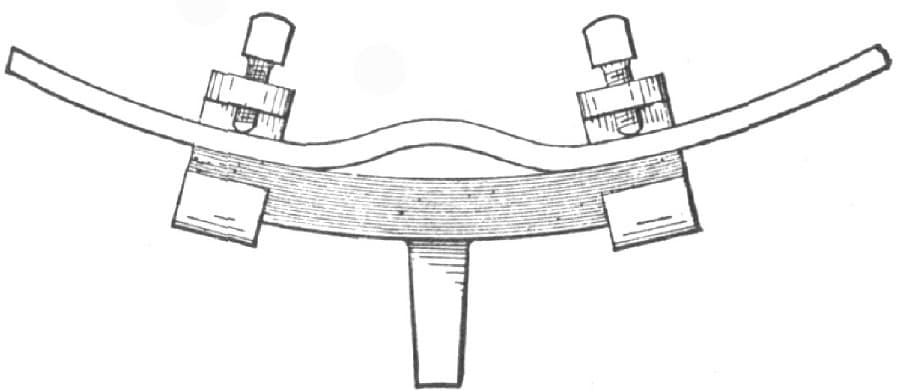
FIG. 155.—SHOWING THE METHOD OF USING THE TIRE-SETTER, NO. 5, FIG. 150
To use it, set the screws to fit the tire, heat to a soft heat and bend as shown in Fig. 155. Then place it in the upset, and let your helper tighten one of the set screws while you tighten the other, and then hammer down with two hammers. In this way a tire can be easily upset 3/8 inch at a heat.
No. 6, Fig. 150, is a very useful implement for cleaning off plow shares or for reducing surplus stock which cannot be removed conveniently otherwise. The cutting face is made of blister steel and the back is of iron welded together. The length is three feet, exclusive of the handle, and the width is 11/2 × 3/4 inches. The teeth are cut hot and like a mill saw’s teeth. To cut them take a sharp wide chisel, commence at the front, cut one tooth, then place your chisel back of the tooth and slide it forward until it comes against the first tooth. This will make your gauge for the second tooth, and you go on in this way until the teeth are all cut. To temper the tool, heat it for its full length to a blood heat, cool, then cover with oil and pass it backward and forward through the fire until the oil burns off. It can then be straightened if it has sprung. The front handle that stands up at right angles to the other part of the tool is screwed in. When the tool becomes dull, it can be softened and sharpened by a half-round file.
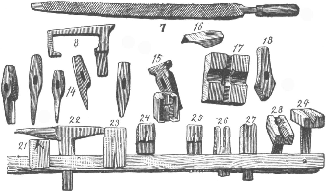
FIG. 156
No. 7, Fig. 156, is a home-made rasp, made of solid cast steel 11/2 × 3/4 inches and 2 feet long (without tang). It has three cutting faces, two sides, and one edge; the cutting edge is swaged round, which makes it very convenient for rasping around collars or similar places; the square edge is left smooth, which makes a good safety edge. It is double cut, similar to the ordinary blacksmith file. It has to be cut hot, and in cutting the second side it will be necessary to place it on the end of a wooden block. It will be found very useful for hot rasping large step-pads, or reducing stock on difficult work.
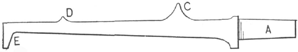
FIG. 157.—SHOWING HOW THE TOOL MARKED NO. 8, IN FIG. 156, IS DRAWN AND FULLERED
No. 8, Fig. 156, is made of 13/8 inches square machinery steel. To make it, draw it down as at A, Fig. 157, to fit the square hole in the anvil, then fuller in, work out the corner at C, draw out and leave the corner at D, and form the foot as at E. Then bend at C and fuller out the corner as at A, Fig. 157, bend D, Fig. 157, as shown at B, Fig. 158, and it will be ready for use. It will be found very handy in making wrenches and different kind of clips, scaffing, dash irons, etc. In many cases it will be preferred to the little anvil at No. 22, Fig. 156, being much firmer on account of the extra leg. At C, Fig. 158, it is 13/8 inches wide, and 7/8 inch deep, and at B, 11/4 × 3/8 inch. The length of the face is 7 inches.
FIG. 158.—SHOWING HOW THE PIECE SHOWN IN FIG. 157 IS BENT AND FULLERED
No. 9, Fig. 150, is a collection of fullers ranging from 11/2 inches to 3/16 inch. The top ones are made of cast steel. Some of the bottom ones are made of iron, and faced with steel, but lately I have made them altogether of machinery steel, which is less trouble to make and answers the purpose very well. I do not think any further description of them is necessary, as any blacksmith can see how they are made by a glance at the illustrations.
No. 10, Fig. 150, is a tool for cutting off round iron. In using it place the bottom swage in the anvil with the long end of the face toward the helper so as to be flush with the front of the anvil. Then place the iron that is to be cut off in the bottom swage, and put the top tool on; let the helper give it a sharp blow and off it goes. Iron from 5/16 inch to 5/8 inch can be cut off thus with one blow. This tool should be made of cast steel. The recess should be made to fit 3/4-inch iron and so deep that the points will rest against the front of the swage and to prevent the tool and the swage from cutting each other.
In Fig. 159 a tool of this kind is shown with the iron in position ready to cut. A is the top tool, B is the bottom swage, and C is the round iron to be cut off.
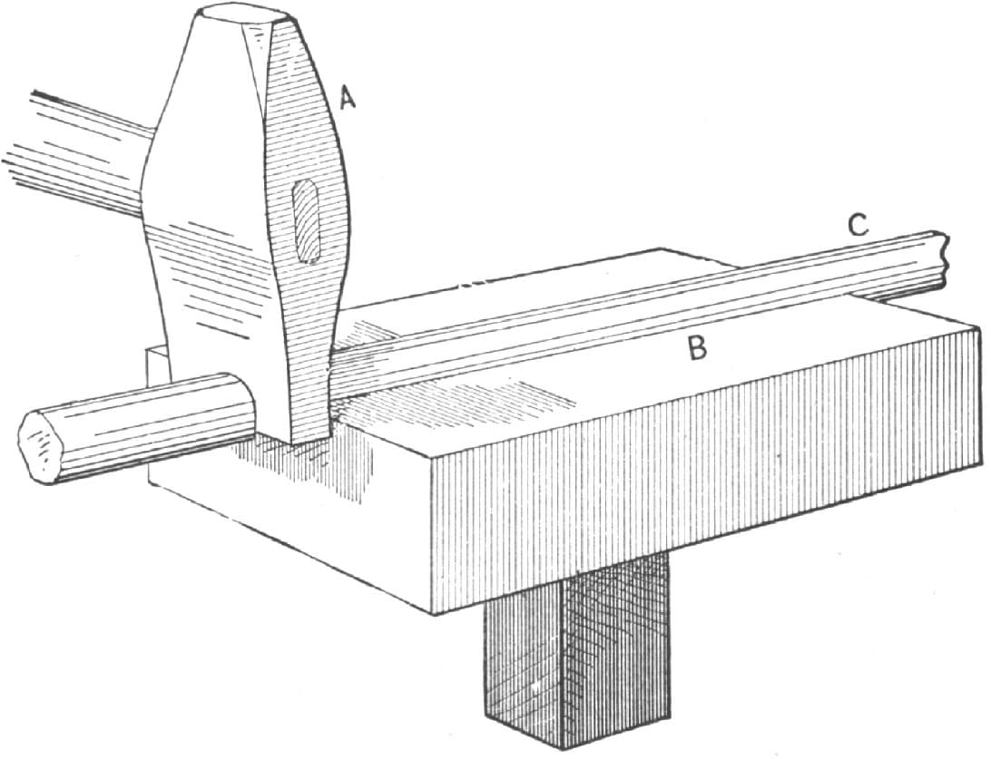
FIG. 159.—SHOWING THE METHOD OF USING THE TOOL MARKED AT NO. 10, IN FIG. 150
In No. 12, Fig. 150, are shown two hardies for cutting iron. The reader will notice that there is a hole in one of them. I use this hole in bending rings from 7/16 inch round to 1/4 inch. The iron is cut off to the desired length, one end is placed in the hole of the hardy, and on the other end I put a suitable heading tool. I then describe a circle around the hardy and the ring is made without heating it.
FIG. 160.—SHOWING THE BOTTOM OF THE SWAGE NO. 15, FIG. 156
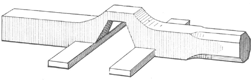
FIG. 161.—A FRENCH CLIP
No. 13, Fig. 150, is a diamond-shaped fuller. It is made the same as those shown at No. 9, with the exception that the face is diamond shape. It is very useful in heavy work in working out corners and will often save considerable filing. Its shape tends to raise the corners, or make it full.
No. 14, Fig. 156, is a number of fine chisels. The first is a hollow or gouge chisel and is very convenient where you want to cut anything circular or hollow. The second is the ordinary hot chisel for cutting off hot iron. The third is a thin splitting chisel and should be rounded on the side toward you, which gives a rounding finish to the cut which is a great deal better where you wish to bend the branches. The fourth is a paring chisel, and is very useful often in trimming where the swell on both sides would be inconvenient. The fifth is an ordinary chisel for cutting cold iron, and should have a stronger edge than any of the others.
FIG. 162.—SHOWING A TOOL USED IN MAKING A FRENCH CLIP
No. 15, Fig. 156, is a top and bottom collar swage. The top tool is about the same as any ordinary collar swage, but the bottom tool differs from any other I have ever seen. In the first place it will be noticed that there is a band around it, projecting above it fully one inch and cut out at each end. This band insures that the top tool will come in the right place every time. In the ordinary collar swage, I have always found more or less trouble in keeping the bottom tool perfectly clean from scales so as to make a sharp collar. To avoid this difficulty I have a hole from the bottom of the collar down through the shank so that the scales work out as fast as made, and now I find the collar comes out clean and sharp every time. To make this tool, forge the swage as usual, with a steel face, then commence at the bottom of the shank and drill a 3/8 inch hole to within 1/2 inch of the face. Drill the rest of the way with a drill about 1/8 inch. The place where the drill comes through is just where the large part of the collar should be. Then prepare it for the collar, then place the top tool exactly over it, mark around and cut so as to have both alike; then put on your band and finish up, and you will have a tool that will give satisfaction.
FIG. 163.—A TOOL USED IN MAKING FRENCH CLIPS
FIG. 164.—SHOWING A METHOD OF USING AN OLD ANVIL IN MAKING FRENCH CLIPS
In Fig. 160, the bottom block is shown before the band is put on. A is the face of the tool, B, the part used to form the collar, C is the shank, and the dots, D D, indicate the hole for the escape of the dirt or scales.
FIG. 165.—SHOWING HOW THE IRON IS FULLERED IN MAKING A FRENCH CLIP
No. 16, Fig. 156, represents a V-chisel which is convenient for trimming out corners, and is especially useful in making French clips; it saves filing and time as well.
Fig. 161 represents a French clip, and Figs. 162, 163, and 164, and Nos. 17 and 18 in Fig. 156, are tools for making such a clip. No. 17 has no shank, but is intended to be used in a cast iron block being held in position by a key so as to be perfectly solid. An old anvil can be made to answer the same purpose by cutting out a recess as shown in A, Fig. 164. To make the clip shown in Fig. 161 proceed as follows:
FIG. 166.—SHOWING FRENCH CLIP READY TO FULLER DOWN WITH TOOL 28, FIG. 156
Take iron of the proper size and extra quality, place it in the large oval bottom tool and with the recess fuller shown in Fig. 162. Then place the iron in the bottom tool, as shown at No. 36, Fig. 175, and flatten out as shown by the dotted lines Fig. 165. The iron will then look as in Fig. 166. Then place it in the tool, No 17, Fig. 156, fuller down and trim up, finally using the tool No. 18, Fig. 156, and the tool shown in Fig. 163, to finish on, and the clip will then be in the shape shown in Fig. 161.
FIG. 167.—SHOWING EYE MADE WITH TOOL NO. 26, FIG. 160
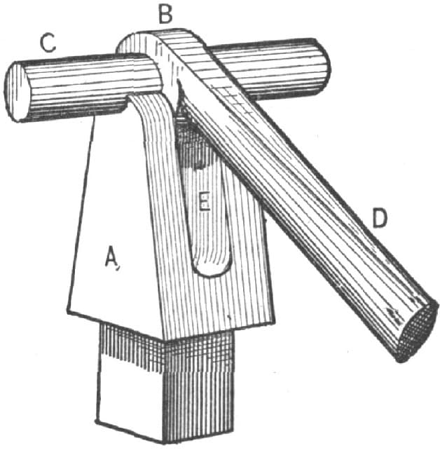
FIG. 168.—SHOWING METHOD OF USING TOOL NO. 26, FIG. 156
No. 19, Fig. 150, represents one-half of a tool used in welding drop steps on body loops. It is used in the vise. It is recessed out to fit shank of step, and the top is rounded so as to leave it strong where it is welded to the loop.
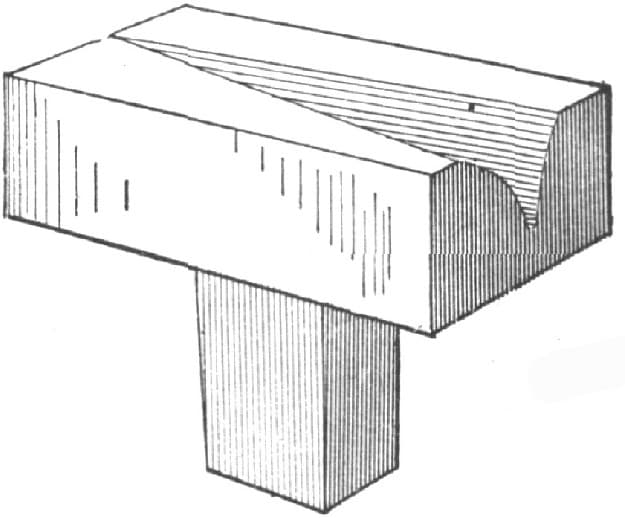
FIG. 169.—SHOWING A TOOL FOR MAKING HARROW TEETH
No. 20, Fig. 150, is one-half of a vise tool intended to be used in forming collars for seat wings, etc.
No. 21, Fig. 156, is a tool for making clips, Nos. 23, 24 and 25 are the ordinary clip tools. Nos. 24 and 25 are set back so as to be convenient for draw-jacks or work of that description.
FIG. 170.—SHOWING HOW THE HARROW TOOTH IS BENT
No. 22, Fig. 156, is a small anvil intended to be used on a larger one. It will be found very useful in light work, such as welding small bends or socket and working up small eyes.
Nos. 26 and 27, Fig. 156, are used in making eyes like those in the ends of top joints, as shown in Fig. 167, and for working up clevis ends. It is very convenient for the latter purpose, because it enables the smith to make a good square corner without straining the iron, and so prevents splitting. Fig. 168 shows method of using tools No. 26 and 27. A is the bridge of the tool, B the eye and C the pin, while D is the part which is held in the hand. The slot E allows the part D to be raised or lowered while hammering on B. In making this tool I use machinery steel. I draw down for the shank, split, fuller out and then dress up.
FIG. 171.—SPECIMEN OF THE WORK DONE BY THE TOOL NO. 32, FIG. 175
FIG. 172.—SPECIMEN OF THE WORK DONE WITH THE TOOL NO. 33, FIG. 175
FIG. 173.—SPECIMEN OF THE WORK DONE WITH THE TOOL NO. 34, FIG. 175
No. 28, Fig. 156, is a tool for forming heads for body loops. It is recessed to the shape of the top of the body loop. It will be found very convenient, and insures getting all the heads of the same shape. I place the head in the tool in punching, which forces the tool full in every part. To provide for the shank the front of the tool is a little higher around the head than at the oval part.
FIG. 174.—SECTIONAL VIEW OF THE TOOL NO. 35, FIG. 175
No. 29, Fig. 156, represents a tool for making harrow teeth similar to the duck’s foot that is thought a good deal of in some parts of the country. Fig. 169 will perhaps give a better idea of the tool, and Fig. 170 will show how the tooth is bent.
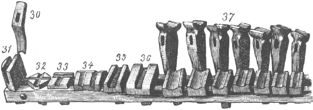
FIG. 175
No. 30, Fig. 175, represents a crooked fuller for use in difficult places, such as gridiron steps, for which it is almost indispensable.
No. 31, Fig. 175, shows an anvil tool used in welding up oval gridiron steps.
No. 32, Fig. 175, is the bottom tool of a cross swage. The same tool is also shown in No. 27, Fig. 156. Fig. 171 represents some of the work done with this tool.
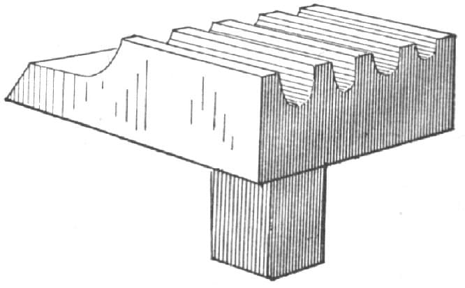
FIG. 176.—THE BOTTOM TOOL SHOWN IN NO. 38, FIG. 178
No. 33, Fig. 175, is the bottom tool of a T-swage. The same tool is shown in No. 28, Fig. 156. It is used a good deal for ironing iron dickey seats, as is also No. 32, Fig. 175, when a double rail is used. Fig. 172 is a specimen of the work done by this tool.
FIG. 177.—SHOWING A SLEDGE FOR HEAVY WORK
No. 34, Fig. 175, is a tool for making corner irons for seats which have rounded surfaces on the inside and flat on the outside. One of the grooves is swedged on both sides of the point or apex of the tool. The other groove is flat on the other side from the one shown in the cut. I use this groove when I wish to make an iron with a foot for only one screw.
No. 35, Fig. 175, is a tool for making horseshoes similar to the Juniata pattern, excepting that the crease is set back so that the center of the shoe projects above the nail heads, thus insuring a good grip of the ground. Fig. 174 is a sectional view of the tool. It is made deeper at one end than at the other so that different weights of shoes can be made with it.
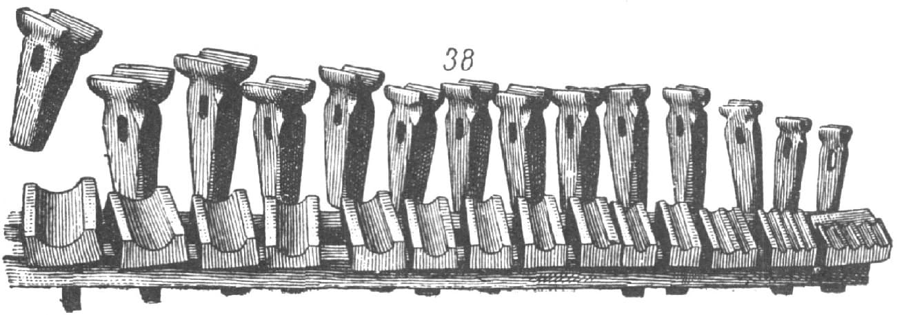
FIG. 178
No. 36 is another punch clip tool.
No. 37 is a group of top and bottom oval swages. They range from 1/2 inch to 11/4 inches, there being 1/8 inch difference between each tool. I think they should range up to 2 inches, but at present I am out of top tools. The latter are of cast steel which I find to give the best satisfaction. For the bottom tools I use iron faced with steel. To make them, I take a piece of square Lowmoor iron, a trifle larger than the square hole in the anvil, reduce it to proper size, cut off about three-fourths of an inch above the part reduced and form it to a head with thin edges. I then take a piece of common iron of suitable size for the top and jump-weld a shank on it, then take a piece of blister steel of suitable size, take separate heats and weld on, then cut off level with the back of the anvil, fuller in the recess and finish up. In finishing up I am careful to have the center a little fuller than the ends, as if it is left perfectly straight it will cut the iron at the ends and in working there is always a tendency for the center to lower.
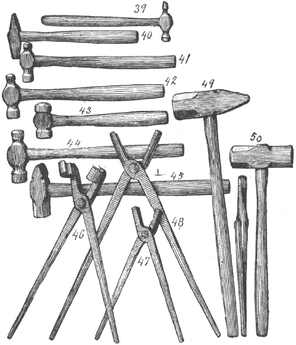
FIG. 179
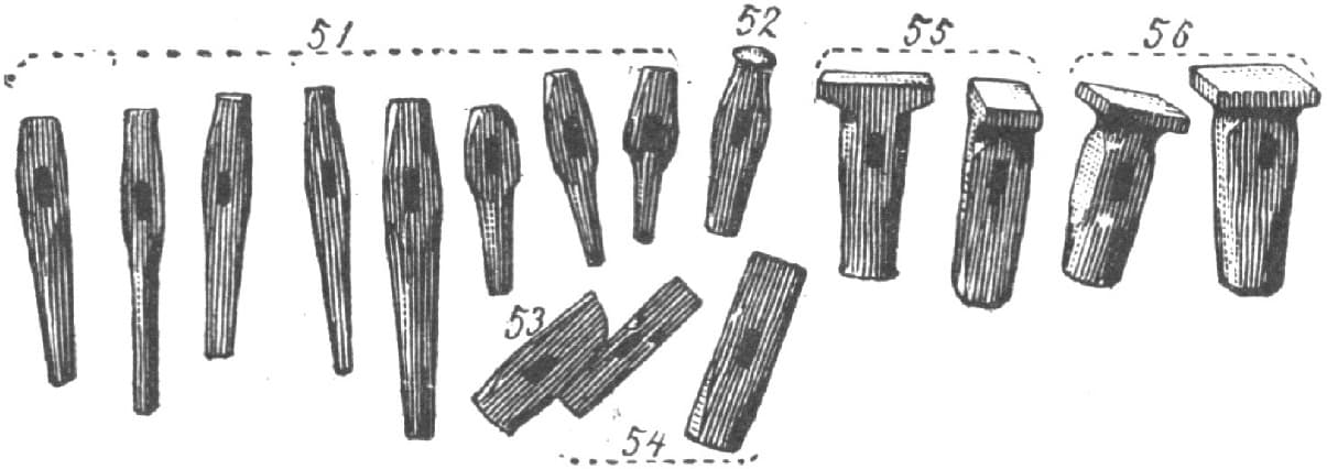
FIG. 180
No. 38, Fig. 178, represents a group of swages for round iron sizes, being 5/16, 3/8, 7/16, 1/2, 9/16, 5/8, 3/4, 7/8, 1, 11/8, 11/4, 11/2, 13/4, and 2 inches. The bottom tool at the extreme right has four recesses, 5/16, 3/8, 7/16, and 1/2 inch, and is made as shown in Fig. 176. The reader will notice that the back edge projects over the anvil and slants, which makes it very convenient for swaging different kinds of clips and by having the swage short it is rendered very convenient also for cutting off surplus ends as shown at No. 10, Fig. 150, but for doing this work the top swage only is used. The swage next to the one on the extreme right at No. 38, Fig. 178. has three recesses, 3/16, 1/4, 5/16-inch. I do not have top tools for the 3/16 or 1/4-inch size but I find them useful in making small half round iron. They are made in the same way as the oval tools. I mark the sizes of the top and the bottom tools.
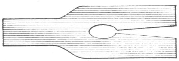
FIG. 181.—SHOWING A FAULTY METHOD OF SPLITTING OUT CROTCHES
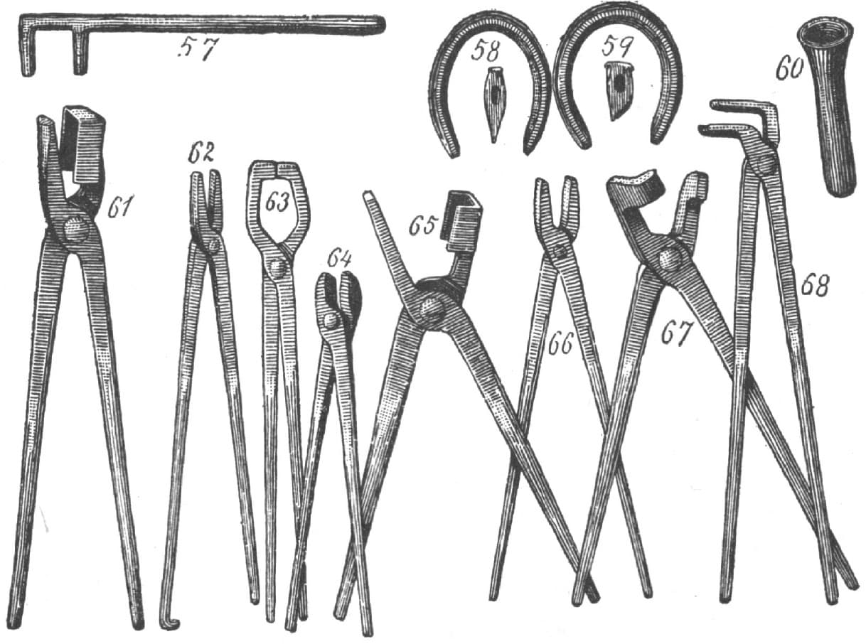
FIG. 182
No. 39, Fig. 179, is a small riveting hammer with a round pein or pane of about 3/8-inch diameter. I think this kind of hammer is best for riveting purposes, as it spreads the rivet every way alike.
No. 40, Fig. 179, is another riveting hammer. It is a cross pane which for some purposes is better than the round pane.
No. 41, Fig. 179, is a light hand hammer, commonly called a bench-hammer, with a globular pane. It is very useful for chipping with a cold chisel, and for light work at the anvil, such as welding dashes, etc. It weighs one pound.
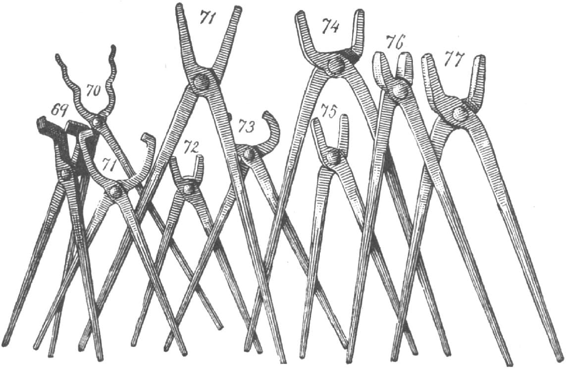
FIG. 183
No. 42, Fig. 179, is the ordinary hand hammer. It weighs 13/4 pounds.
No. 43, Fig. 179, is a horseshoe hammer, very short and compact, being two-faced, one end being slightly globular to answer for concaving. Its weight is 13/4 pounds.
No. 44, Fig. 179, is a heavy hand hammer similar to Nos. 41 and 42. It weighs about 21/2 pounds.
No. 45, Fig. 179, is a large cross pane hammer made very plainly. It is useful in straightening heavy, irons, and also for the helper as a backing hammer on light fullers.
No. 49, Fig. 179, is an ordinary sledge hammer in which the eye is near the center.
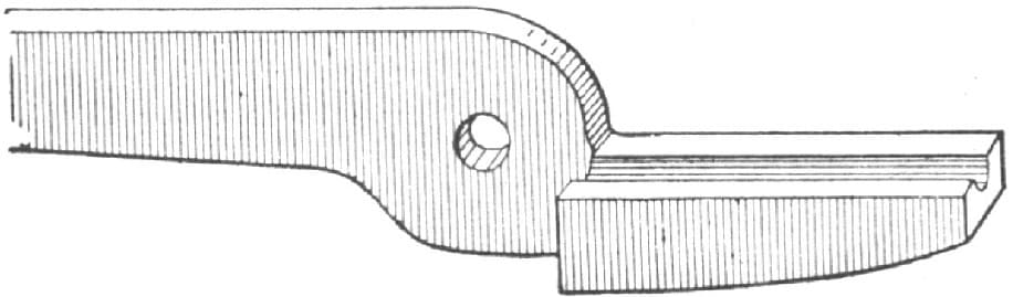
FIG. 184.—SHOWING A RIGHT HAND JAW FOR TONGS
No. 50, Fig. 179, is a horseshoe sledge, but it should be rather shorter and more compact than it appears in the illustration.
Fig. 177 represents another sledge. It will be noticed that the eye is nearer the top of the sledge, and I think this is an improvement for heavy work where the smith wants to swing overhead.
No 51, Fig. 180, is a group of punches. The first two on the left hand side are oval or eye punches. The oval stand on the corner of the square so as to have the handle in the most convenient position, and are used for punching eyes, or where the smith wishes to swell out in order to strengthen by punching an oval hole first and then driving a round pin in afterwards. They can be used to good advantage in splitting out crotches, as there is less danger of cold sheets than when the smith cuts right up with the chisel as shown in Fig. 181.
The next two in the illustration are square punches, and the next four are round punches of different sizes.
No. 52, Fig. 180, is a bob punch. It has a face similar to a countersink only more rounding. It is useful to press a cavity in a flat piece of iron where a jump-weld is to be made, as in welding shanks to bottom swages, also for T welds.
No. 53, Fig. 180, is a side-set hammer which is very handy for working up an inside corner or any place where you have to weld two irons in the shape of angle iron, or on the landside of a plowshare.
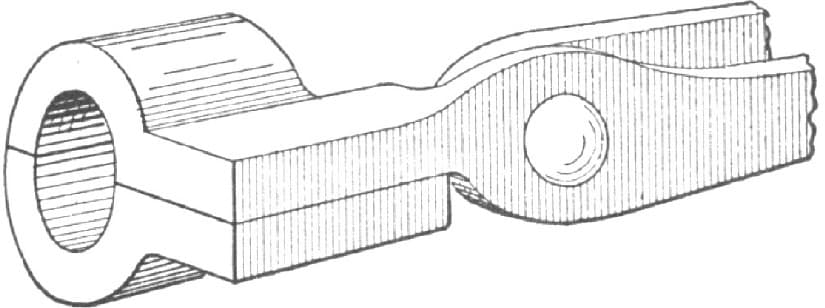
FIG. 185.—SHOWING HOW THE JAWS OF THE TONGS NO. 46, FIG. 179, ARE MADE TO FIT ROUND IRON
No. 54, Fig. 180, represents two set hammers, one being 1 inch and the other 11/2 inches square. They are very useful in making many kinds of clips, and numerous other jobs.
No. 55, Fig. 180, also represents two set hammers similar in make but with the eyes punched from different sides. They are useful in plow work and are often used as flat hammer, where there is not room enough for the ordinary flat hammer.
No. 56, Fig. 180, represents two flat hammers, the smaller having a face 21/4 inches square, while the larger is 21/2 inches. This tool is to the blacksmith what the plane is to the woodworker. It is what we generally calculate to finish all flat surfaces with.
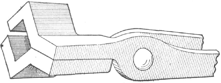
FIG. 186.—SHOWING TONG JAWS MADE FOR HOLDING LONG SQUARE IRON
We now come to the tongs, and just the same as with everything else, there is a right and a wrong way to make them as tongs are right and left-handed. The accompanying illustration, Fig. 184, represents a right hand jaw. It is not often that a pair of left hand tongs are made, and, as a rule, if a smith does such a thing by mistake in a shop where there are many working, it produces so much merriment that he scarcely ever forgets it, yet I have seen a man of several years’ experience do such a thing.
No. 70, Fig. 183, is a pair of pick ups. They should be kept in a staple in front of anvil block, or else hung convenient on the side of tool bench. They are used by the helper to pick up pins or anything else. They will easily catch anything from 2 inches downward.
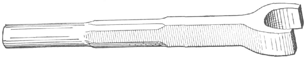
FIG. 187.—TOOL USED IN MAKING KEEPERS FOR DEMAREST WAGON SEATS
No. 69, Fig. 183, is a pair of side tongs. No. 67, Fig. 182, is another pair of the same kind, but larger, which are very useful for holding flat iron. There is a sort of calk turned on one jaw to prevent the iron slipping sideways.
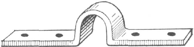
FIG. 188.—KEEPER MADE WITH THE TOOL SHOWN IN FIG. 187
No. 62, Fig. 182, is a pair of snipe bills, which are very handy for small bands, sockets or eyes. One of the jaws is round and the other is square, and a fuller mark is made up the center, which I think is better than making both round, as it fits both the outside and inside of band. They are drawn quite small at the point. The back ends answer for a pair of clip tongs to draw on clip bars with.
No. 48, Fig. 179, is a pair of hollow jaw tongs which are very useful for holding round iron. Every blacksmith should be provided with three or four pair ranging from 3/4 inch upward. I always fuller up the center of my ordinary tongs so that they will hold small round iron well. They will hold flat iron all the better for it.
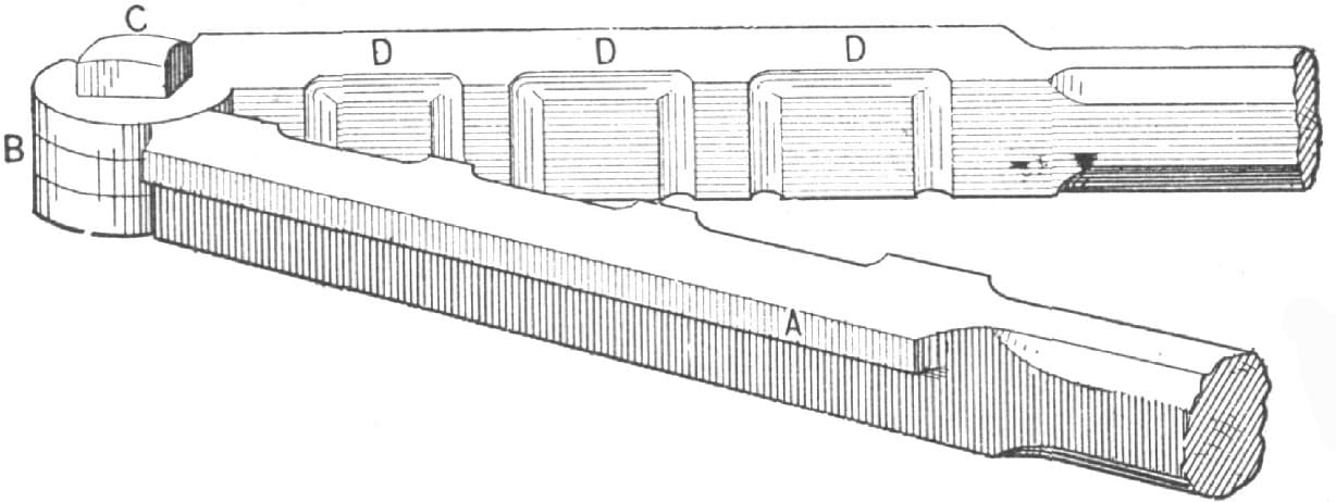
FIG. 189.—TOOL USED IN MAKING CLIPS
No. 60, Fig. 182, is a cupping tool. It is hollowed out with a countersunk drill and is very useful for finishing off nuts or the top of square-headed bolts. Four sizes of these make a very good set, but the largest one should have a handle.
No. 58, Fig. 182, is a horseshoe stamp which is to common to require any description.
No. 59, Fig. 182, is a creaser. I like it to be hollowed slightly on the inside face, as I think it follows the round of the shoe better.
No. 64, Fig. 182, represents a pair of horseshoe tongs. The jaws are short and round so as not to project far inside of the shoe and be in the way of the horn of anvil, and at the same time to allow the smith to shift the position of the tongs without losing their grip.
No. 68, Fig. 182, is a pair of clip tongs which are indispensable in welding up whiffletree clips. The outside jaw is rounding, while the inside or short jaw is concaved to fit outside of the clip.
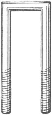
FIG. 190.—CLIP MADE BY THE TOOL SHOWN IN FIG. 189
No. 71, Fig. 183, is a pair of coulter tongs. One of the jaws turns down on each side of the coulter shank which makes the tool very convenient for holding. No. 65, Fig. 182, are similar tongs which are very useful for holding square iron.
No. 46, Fig. 179, is a pair of tongs for holding large round iron. They are very convenient for holding large bolts as the smith can let the head project back of the jaws. They are similar to to the tongs shown in No. 69. Fig. 183, excepting that both jaws are hollowed to fit the round iron as shown in Fig. 185. Fig. 186 represents a pair of tongs for holding long square iron.
Fig. 187 represents a very simple and handy tool for making keepers for Demarest wagon seats. I usually make them of 7/8-inch band iron. To make them I place a piece of 1/2-inch round iron on the anvil, lay the band iron across it, then place the top tool, Fig. 187, strike two or three blows, and the job is done as shown in Fig. 188.
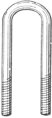
FIG. 191.—SHOWING HOW THE CLIP IS BENT BY THE MANDRIL
Fig. 189 shows a tool for making clips of round iron as illustrated in Fig. 190. This tool will save a great deal of time and do good work. The clips are used largely in some shops for clipping on springs, etc. The tool is intended to be used in the vise and has a projecting part, as shown at A, to rest on the vise. It is intended for three different sizes of clips, 11/4, 11/2 and 13/4 inches. To make it take a piece of 1-inch square iron, fuller along the center with a 3/8 inch fuller the length of jaw. Then use the set hammer on the lower side and reduce to 3/4 inch thick; then use the side set hammer to true up; plunge and form the joint as at B, taper down for handles and weld on a piece of 5/8 inch round iron so as to make a handle one foot long. The jaw is 9 inches long, measuring from the bolt hole. After both jaws are made put in the bolt C, clamp firmly together and drill six holes the size and width of your clips. Be careful not to drill any larger as the clips require to be held firmly. If a little small they can easily be opened a little on the sides with a round file. Then with a rounding chisel cut the corners as shown at D, D, D, and smooth out with the end of the file and it is ready for use. To make the clip, cut off the desired length of iron and screw ends, bend on a clip mandril as shown at Fig. 191, then place in the tool, grip firmly in the hand, give a few sharp blows on the top with a suitable swage and you have a clip similar to that shown in Fig. 190. Fig. 192 is a sectional view of the tool.—By AMATEUR.
FIG. 192.—SECTIONAL VIEW OF A SIDE OF THE TOOL SHOWN IN FIG. 189
ABOUT HAMMERS.
Nearly every one has noticed the name of David Maydole stamped upon hammers. David Maydole made hammers the study of his lifetime, and after many years of thoughtful and laborious experiment he had actually produced an article to which, with all his knowledge and experience, he could suggest no improvements.
Let me tell you how he came to think of making hammers. Forty years ago he lived in a small village of the State of New York; no railroad yet, and even the Erie Canal many miles distant. He was the village blacksmith, his establishment consisting of himself and a boy to blow the bellows. He was a good deal troubled with his hammers. Sometimes the heads would fly off. If the metal was too soft the hammer would spread out and wear away; if it was too hard it would split. At that time blacksmiths made their own hammers, and he knew very little about mixing ores so as to produce the toughest iron. But he was particularly troubled with the hammer getting off the handle—a mishap which could be dangerous as well as inconvenient. One hammer had an iron rod running down through the handle with a nut screwed on at the end. Another was wholly composed of iron, the head and handle being all one piece. There were various other devices, some of which were exceedingly clumsy and awkward. At last he hit upon an improvement which led to his being able to put a hammer upon a handle in such a way that it would stay there. He made what is called an adze-handled hammer, the head being attached to the handle after the manner of an adze.
The improvement consists in merely making a larger hole for the handle to go into, by which device it has a much firmer hold of the head, and can easily be made extremely tight. Each hammer is hammered out of a piece of iron, and is tempered over a slow charcoal fire, under the inspection of an experienced man. He looks as though he were cooking his hammers on a charcoal furnace, and he watches them, until the process is complete, as a cook watches mutton chops.
The neighborhood in which David Maydole lived would scarcely have required a half-dozen new hammers in a year, but one day six carpenters came to work on a new church, and one of these men left his hammer at home and came to David Maydole’s blacksmith shop to get one made. The carpenter was delighted with it, and when the other five carpenters saw it, they came to the shop the next day and ordered five more hammers made. They did not understand all the blacksmith’s notions about tempering and mixing the metals, but they saw at a glance that the head and handle were so united that there never was likely to be any divorce between them. To a carpenter building a wooden house, the removal of that one defect was a great boon. A dealer in tools in New York City saw one of these hammers, and then David Maydole’s fortune was made, for he immediately ordered all the hammers the blacksmith could make. In a few years he made so many hammers that he employed a hundred and fifty men.—From “Captains of Industry,” by JAMES PARTON.
DRESSING UP OR FACING HAMMERS, REPAIRING BITS OR DRILLS.
Good tools are among the most essential things about a blacksmith shop. You need a good fire, a good anvil, and also a good hammer. You may have fire, anvil, and all your other tools in good shape, but if your hammer is rough and broken you cannot do good work, nor do so much in a day. I think that every man who calls himself a good blacksmith should be capable of dressing his hammer. But for the benefit of those who are just beginning the trade I will give my way of doing this job.
In the first place I open the middle of my fire and fill it up with charcoal, using the mineral coal only as a backer. Heat only the face you wish to dress as by so doing you will not change the shape or disturb the eye. Upset on the face and draw down on the sides. If the face is broken very badly it maybe necessary to trim off a little, but by upsetting and drawing down several times you can get quite a large break out without much trimming. After you have completed the forging it is a good plan to put the hammer in the dust of the forge and let it anneal; and then it can be leveled with a file and ground off smooth.
To temper it, heat only the part you wish to harden, to a good red, dip and hold under water until cold. Then have a thick ring (an old ax collar will do) that the face of the hammer will go through while the sides will come in contact with the ring, heat the ring hot and place it over the hammer, turn the ring slowly so as to keep the heat even on all sides at once, draw until it shows a little color, then try with a fine sharp file, and when you can make the file take hold it has drawn enough. There are so many grades of steel and different temperatues of heat and water that you cannot always rely on the colors. The middle of the face should be left as hard as you can keep it, for if you let the heat from the eye part run down and draw the face, it will be too soft and settle, leaving the outside circle the highest. If the tool is double-faced do all your forging and finishing before you temper. Then after you have tempered the largest face, wind a wet cloth around it and keep it cold while you are heating the other face.
I think that round sides with the outside edge rounded in a little, stand better than the square or octagon. Get a good handle and put it in so that it will stay.
Every one who does repairing breaks a good many bits, especially small ones. They usually break at the end of the twist, leaving the shank long enough to make another bit by flattening about an inch of the end and twist once around. Then hammer down the edge, file a diamond point leaving the cutting part a little larger than the seat of the bit, temper and you have a drill as good as new. Drills can be made in the same way.—By F. P. HARRIMAN.
HAMMERS AND HANDLES.
Almost every blacksmith has a different style of hammer or handle, and every one thinks that his way of making them is right. One wants a heavy hammer and another a light hammer, for the same kind of work.
One wants a long hammer and another wants a short one. One wants his hammer to stand out and another likes his to stand in. One wants a long handle and another prefers a short handle. One wants his handle to spring and another does not. And so it goes on in that way all through the country.
Everyone will tell you that his way is the best, and will explain why it is the best. Now, my opinion in regard to the above is that they are all in almost every case right. I make all my hammers and handles, and think they are the right kind, simply because they suit me and I can do the work required with them satisfactorily.
I do not claim that there is any right way to make a blacksmith’s hammer, But, of course, there is a certain line that you cannot pass without going to extremes.
For instance, if you should make a hammer a foot long, with a handle ten inches long, that would be out of all proportion, and would not be convenient to work with, and it could not be said by anyone that it was right. But supposing one man makes an ordinary hammer with a long pane, another makes one with a short pane; each one will claim that his hammer is right and that he could not do his work as well with another.
Now, how shall we determine which hammer is the nearest right? I should say both are right, for as long as they can do the work required, and they are satisfied with their hammers, that is all that is necessary.—By G. B. J.
A HAMMER THAT DOES NOT MARK IRON.
I was in a country blacksmith’s shop the other day, and while talking with the boss I noticed a workman who was trying to get the kink out of an axle spindle with a hammer and swage. Every “lick” made it worse and filled it with hammer marks. I offered to show him how to make a hammer that would do the job properly. The offer was accepted, and this is the way the hammer was made. I first called for about four or five pounds of old lead. This was furnished, and I then took a piece of three-quarter-inch round iron about fifteen inches long and upset the end, as shown in A, Fig. 194 of the accompanying illustrations, to about 11/8-inch and tapered it to B, a length of 2 inches. This left the handle portion C about 12 inches long. I next got a box full of yellow mould, formed a circle in it of about two inches in diameter and placed the handle at the center. With a piece of sheet-iron I made a ladle, melted the lead and poured it into the impromptu mould. After a wait of twenty minutes I lifted my hammer out of the sand, dressed it up with a hand-hammer and then the job was finished.
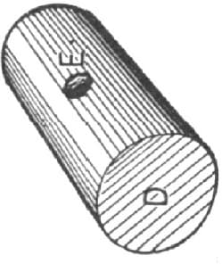
FIG. 193.—SHOWING THE HAMMER-HEAD
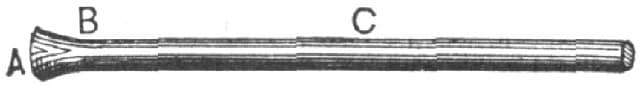
FIG. 194.—SHOWING THE HANDLE
In Fig. 193 D is the hammer, and E is the place occupied by the handle. Fig. 195 illustrates a simpler method of making the tool. A hole is made in the sand as at D, and the handle is stuck in at E, then the lead is heated and poured in. These hammers will not mark the iron.—By IRON DOCTOR.
AN IMPROVED TUYERE.
When I first began to work at the forge, nearly fifty years ago, the old bull’s-eye tuyere was the best in use, but soft coke (or “breese” as it was called, being the refuse of the rolling mill furnaces), coming into use disposed of the bull’s-eye, so the water tuyere was invented as a necessity. For more than thirty years I heard its gurgling waters, always looking upon it as an evil to be tolerated because it could not be avoided. Fancy all your fires started on Monday morning in the winter, temperature below zero, water just getting warm and then finding pipes all bursted, new ones to be fitted, corners to be bent in one of the forges at the risk of spoiling a tuyere for want of water in it, customers waiting, foreman swearing, men freezing and shop literally upside down.
FIG. 195.—SHOWING A SIMPLER METHOD OF MAKING THE TOOL
Next came the tank and tuyere in one, a good improvement; also the coal back made of wet “slack,” but owing to its extravagant use of fuel not to be tolerated. Then came the bottom blast. I do not know when or where its first originated (invent or a “crank,” no doubt).
As I was determined to do without a water tuyere, if possible, I tried most of the fancy “turn ’ems and twist ’ems” in the market, patented and otherwise, and all of them spread the fire too much for economy, in fact, some of them made a series of fires all over the hearth—the tuyere getting hot and clinging to the “clinker” with a matrimonial tie never to be divorced until one or both of them was deadly cold—making me hot, too, both in body and temper. I then got the tuyere craze and schemed all sorts of “jimcracks,” if possible, worse than the others, until at last I concluded that moving blast orifices in tuyeres at the bottom of a forge fire were out of place, worse than useless, the poker being all sufficient; and to keep the tuyere sufficiently cool to prevent the clinker from clinging, it only wanted a lump of iron big enough where the fire could not touch it to keep the part cool where it did touch. Coming across an old cannon-ball, which, I suppose, had been used to knock down the walls of Petersburg during the war, and big enough it was, for the matter of that, to knock down the walls of—well; I won’t say where—it being about nine inches in diameter and weighing upward of one hundred pounds, I said to myself, “Here is my tuyere.” So I bored a hole in one side and screwed a piece of 3-inch wrought iron pipe into it, then giving it a quarter turn on the face plate I bored a 21/2 inch hole at right angles and into the other. I then drilled three 3/4 inch holes in the other side and chiseled them into a mouth for the blast 21/2 inches by 3/4 inch, which is a good size for the fan blast for regular work. I prefer a flat hole to a round one for the bottom blast, as it does not allow so large a cinder to fall through when the blast is off. After putting a trap door at the bottom to empty the tuyere I fixed it on the hearth 6 inches below the level of the top of the hearth, making a fine brick basin, as shown in section in the accompanying engraving. The success of this tuyere is complete, the blast coming straight out of the mouth like shot from a gun, making the fire very intense at the proper place (not spreading all over the hearth), which economizes the fuel as far as possible consistent with the work to be done, and the mass of metal always keeps the tuyere cool and cakes the clinker so as to make it easy to lift out of the fire with the poker, no matter how long or how heavily it is worked. Should anyone feel disposed to try it he will be more than pleased. The forge and anvil should be both on a level to permit the crane to operate easily without trouble.—By IRON JACK.
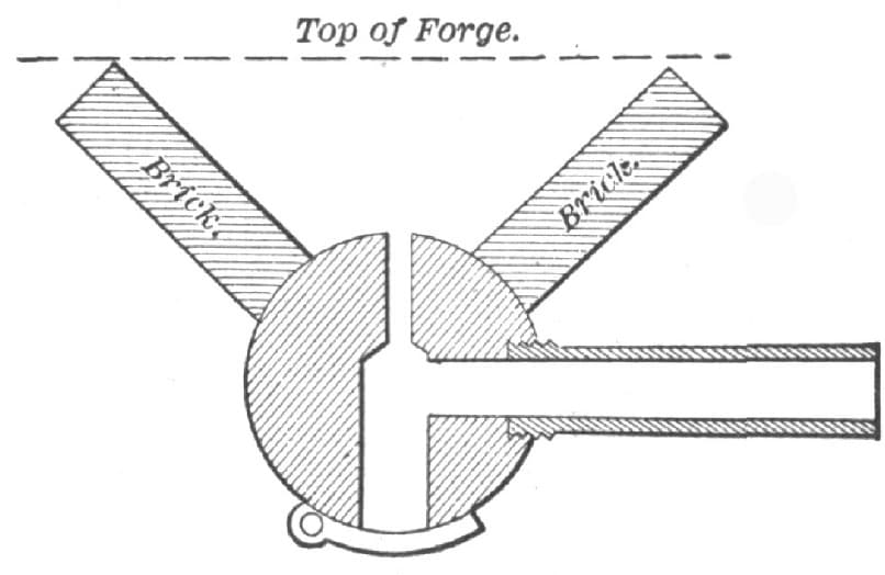
FIG. 196.—IMPROVED TUYERE, AS MADE BY “IRON JACK”
HOME-MADE BLOWER.
I commenced business without tools and without any other resources than my own strong right arm. After getting an anvil I experienced the need of a blower. Those which were for sale were high priced, and nothing but the cash in hand would buy one. In order to do the best possible under the circumstances, I took a good look at one in a store, by which I obtained the principle on which it was operated, and then went home and commenced work upon one upon my own account. I made it of wood, and succeeded so well as to make something by which a sort of a fire could be started. When it was in motion, however, my neighbors thought I was running a threshing machine. It could be heard of a still morning nearly a mile away. After using this for a short time, I concluded I would try to make a better one, and now I will tell you how I set about it.
I took three pieces of white pine plank, 12 by 14 inches and 11/2 inches thick. I dressed and glued them together crosswise, in order to obtain the greatest possible strength. I took the piece to a jig-saw, and had a circle, perfectly true, taken out of the center, 8 inches in diameter. I then closed this hole by placing a half-inch poplar board on each side, the same size as the large block. These thin pieces I screwed down tight with eight screws on each board. Removing one of them I got the center of the edge of the hole on the inside of the one that remained, and by reversing the operation, got the center upon the opposite one. From this measurement I cut a hole 4 inches in diameter through each of these thin pieces, which was to serve to let the air into the blower. By placing the boards back in their original position the holes would be in the center of the hole cut in the large block.
FIG. 197.—GENERAL SHAPE OF THE PADDLES OR FANS IN “NO NAME’S” BLOWER
I next took two pieces of iron 1/2 by 11/4 inches and drilled a 5/16-inch hole through them in the middle. I took a piece of 3/8-inch steelrod and made two thumbscrews of it; cut threads upon them to work tightly in the holes in the irons. I made them very pointed and chilled them very hard. Next I took a piece of 3/8-inch steel rod and cut it the right length to fit between the points of the two thumb-screws, and with the center punch I made a small puncture in the center of the ends of this rod to receive the pointed ends of the thumb-screws, above described. Next I drilled two holes in this shaft, one about 11/2 inches from one end, and the other about 2 inches from the pulley end. On the long end I placed a small cotton spindle pulley, and 11/4 inches in diameter and 1/4 of an inch thick, having a groove in its surface for a small round bolt, such as is frequently used on sewing machines. I next took a piece of sheet iron, heavy gauge, and cut some paddles or fans 4 by 8 inches, in shape as indicated by Fig. 197, accompanying sketch. I riveted these fans to shaft and bent them up, thus forming four paddles, located at equal distances apart. The fan was now done, except putting together. I screwed fast the straight pieces of iron that held the thumb-screws and took care that the screw came exactly in the center of the hole, in order that the fan should turn freely. I turned the box over and placed the fan in the hole, with two pivots together, and then fastened in position the other piece of iron, which was made in the shape shown in Fig. 198 of the sketches. I exercised great care that it also should come exactly in the center and at the same time be in such a position as not to come in contact with the bolt. I took care also that the face hung perfectly true in the center and then screwed down the second board. I next made a hole in the end of the box 3 inches in diameter, making it to intersect with the hole in the box at the upper part. I took care that it should be smooth and clean. I made a frame of 2 by 3 hard wood in such a way as to mount the blower in a convenient position near my forge. A driving-wheel grooved on the fan to accommodate a bolt of the kind above described, and operated with a crank, is fastened to two standards at the front of the frame, thus affording motive power. My fan, constructed in this manner, has now been in use over two years, and is in perfect condition at the present time. It gives all the blast that I require, and runs noiselessly.—By NO NAME.
FIG. 198.—SHAPE OF SIDE IRONS HOLDING THE AXLE OF FAN IN “NO NAME’S” BLOWER
FIG. 199.—PATTERN OF FANS, TO BE MADE OF GALVANIZED IRON
FIG. 200.—CENTER-PIECE TO WHICH FANS ARE ATTACHED
FIG. 201—SIDE PLATES, BETWEEN WHICH FANS ARE FASTENED
FIG. 202.—CROSS SECTION THROUGH COMPLETED FAN
HOME-MADE FAN FOR A BLACKSMITH’S FORGE.
I think anyone with ordinary mechanical skill, by following the directions which I shall attempt to present, will have no difficulty in building a fan which will perform satisfactorily.
First cut twelve piece of galvanized iron to the shape and dimensions shown in Fig. 199. These should be about 1/16 of an inch thick. Four square studs about three-quarters of an inch long, are left on the edges of each plate. The distance from A to A is 31/2 inches, from B to B, 41/2 inches, and from C to C, 41/2 inches. Punch two full quarter-inch holes in each piece. Make a middle piece of metal like Fig. 200, which should be about five inches in diameter, and seven-eighths or an inch thick. This can be made of brass, zinc, or iron. Drill two holes in each arm to match the holes in plates shown in Fig. 199. Than put two of these plates on each arm, with quarter-inch bolts as is shown at A in Fig. 200. Then cut two circular plates after the pattern shown in Fig. 201. These are to be dished as shown in Fig. 202, in order to fit the middle of the fan nicely. Have them quite as large as the middle of the fan. In the center of these plates are draught holes, B, through which the air will enter the fan. These are to be four inches in diameter. Each plate has twelve long narrow holes punched in it as shown in Fig. 201, and a strong zinc washer is soldered upon it. This plate is now forced on to the side of the fan. The studs will of course project through this plate rather more than half an inch. By taking a chisel or screw driver, and putting it between the studs or lugs, one part can be turned one way and the other the other, as in Fig. 201, and the plates will be fast. A good bit of solder should then be run over the whole, as shown by the dotted lines at F in Fig. 201. The next thing is to take two of pieces 11/4 inch plank, and cut them to the shape shown in Fig. 203. They should be grooved as shown by the dotted line about one and one fourth inches from the edge. This portion is to form the box for the fan. Fig. 204 shows the fan put together, but with one side and one plate removed. Now a sheet of iron 3/32 of an inch thick, and say five inches wide, must be bent to the shape of the groove shown by the dotted line in Fig. 203. Put this into the grooves between the two wooden sides, and bolt all together with quarter-inch bolts and nuts. The bolts should be put in four inches apart all around. Zinc bearings four inches wide should be used, and the whole made to fit firmly to a one-inch board about twelve inches wide. Turn a wooden pulley, about three inches in diameter, with a convex face, something like that shown in Fig. 205. The spindle of this pulley should be three-fourths of an inch in diameter, and eighteen inches long. The outlet at the mouth of the fan is four inches square. The nozzle in the fire can be made two inches, or any desired size.—By K.
FIG. 203.—SIDE ELEVATION OF COMPLETED FAN
FIG. 204.—LONGITUDINAL SECTION THROUGH COMPLETED FAN
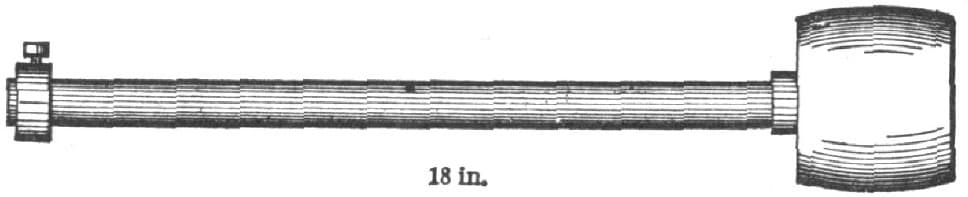
FIG. 205.—SPINDLE AND PULLEY FOR DRIVING THE FAN
MINERS’ TOOLS AND SMITH WORK.
When I was on Ballarat Diggings from 1852 to ’59 there were sledge hammers in use for various purposes; thus in my shop I had sledge hammers for the ordinary strikers, which weighed say, 14 lbs. each, and as a sort of corps de reserve, one of 28 lbs.; and as a good striker was not always to the fore, I usually wielded a hand hammer myself of 4 lbs. for sharpening the miners’ picks, for which I received when a “rush” was on, 2s. per point, never less than 1s. 6d. per point, 2s. 6d. for steeling, and 5s. for laying and steeling; also I got 10s. for making an ordinary Cornish hammer-headed driving pick. I think that the weight I stated would be about the average for striking the heads of jumpers for quartz reef, and what we termed cement, which might be likened to masses of stone, imbedded in a slaggy sort of glass; but as those engaged in the search for the precious metal were representatives of, say, every country, calling and want of calling upon this sublunary sphere, so were the tools and the “ shooting irons” which came to me for repair.
I was renowned for tempering the miners’ gear. I think that about 1 in 500 smiths is fit to be trusted to manfacture any tool from cast steel without over-heating same. I have not been brought up a blacksmith, being more in the line of a fitter of the knotstick species, and I have not yet met with a blacksmith that I would trust to forge me any kind of tools for lathe, etc. Now, please to bear in mind that this does not apply to men who make specially of tool-making but only to the ordinary general men of the shops. A dull red in a dusty place is not enough for the welfare of cast steel, but this entails a lot of additional hammering, which tells upon a man’s wrist in an unpleasant manner. At same heat I dip drills or jumpers steadily into ordinary water not containing any sort of quack medicines therein.
A proper smith’s hand hammer always has a comparatively small rounded pane, the pane for drawing-out purposes being upon the sledge hammer, but I employed out on the Diggings for all-round jobs a German, who probably could make anything complete with hammers alone, from an elbow for stovepipes to figures and foliage, and he spoke of having alongside the anvil in Germany, say some fifty different sorts and weights of hammers.
To stop the ring of an anvil. Let the spike, which ought to be in the block to keep the anvil in situ, fit the hole in it tight, and let the adjacent iron of the anvil’s bottom bed upon said block, and its vibration will be stopped once for all. The reason why we don’t have more articles upon smithwork is undoubtedly because, in the bulk, English smiths are uneducated, and like all such, grudge to afford any information upon that or any other subject, and they abound in quasi nostrums for accomplishing many things.
With regard to making a weld, one of your correspondents says: “Dip each piece in sand,” etc. Now, there are many varieties of sand, such as that about here, which is deficient in the matter of silica, which I opine is the material which, by melting at the necessary heat just previous to the melting of the iron, forms a coating of glass over the iron, and so prevents its oxidation during its heating and transit to the anvil; therefore, I find it better to collect the bottoms out of a grindstone trough, taking care that no debris of zinc, copper, lead, tin or anything abounding in sulphur, be used upon said stone; and he has omitted to mention that an important factor in a sound weld is that, at the instant of taking the two pieces to the anvil, the operator, or operators, should strike each piece gently, behind the heated part, upon the anvil, in order to knock off all impedimenta; with lightning rapidity, place one upon the other, tap gently upon the “center” of the weld, and quickly close up the two thin ends, but bearing in mind to work from the center to the outside.
An amateur will find that a serious difficulty will be encountered when he tries to hold anything, more especially cast steel, in a tongs. When learning how to turn the work upon its side, be sure to turn so that the “back” of the hand is uppermost, or a bad striker will be likely by lowering his back hand to plant a lot of the hot slag into the palm of your hand, or you may accomplish this by bad striking upon your own account. When hitting a job upon the anvil, do not strike in various places, as a rule, unless when necessary to place the work over a particular part, as the edge or on the beak. Keep your hammer going up and down, as if it were in guides, drawing the work back or forward as required.
There is an art in making and keeping up the fire. It depends very much upon the fuel used. If a heavy welding heat be required, we must take two or more shovels of wet slack (after, of course, lighting up) and tamp this down gently with the shovel, so that it forms an arched oven, as if were, and poke a hole or holes to run in the bar or plural. If we observe a blue or greenish tinge in the flames, we will probably consider as to the advisability of shoveling off “all” the fire and beginning again, as sulphur is in the ascendant.
Sulphur would cause the white-hot iron to run away in drops. Mine is a portable forge, and by drawing out the plug at the back in the air-pipe when knocking off for a spell, this not only allows the entrance of air to keep fire alight, but prevents the liability there is to blowing up a bellows, if fresh coal is put on, and immediately after, more especially if it be wet slack, the blowing be stopped, as in this event the large quantity of gas generated finds its way into the said elbows, and when the culprit next draws down the handle, he mixes it with the air, and a violent explosion is the result, as well as probably the splitting of the inside middle board. This is the reason why the nozzle of an ordinary bellows ought not to be jammed into the tuyere; but there should be, say, 1/4 inch clear space around its end. A steady continuous blast is far more efficacious than short jerky forcing.
The putting of salt or anything else in the water for tempering is bosh.
When a smith applies to me for a job, I always set him—if in want of one—to make his hammer and a pair of tongs. When an amateur can make a tongs that does not open when it ought to shut he will know a thing or two anent forging, and when a smith can make a good cast-steel hammer, it is tolerably certain that he is up to the hammer, and if he doesn’t want to wet it too often, deserves taking on.
As to the silent language, it would never do if one had to say to a striker, “Will you be kind enough to hit so and so?” therefore if we want the striker, we ring on the hand hammer; he is all attention. We whip out the bar and gently tickle it together whilst in a melting mood; next, we tap it in an inviting manner upon the spot where he ought to strike it, which, as before stated,’ should, as a rule, be in the center of the anvil. At first both strike alternately, but as the reducing effect of the sledge becomes evident, we, the smith, judiciously intersperse our blows upon the jobs by taps upon the anvil, always shifting our irons; but unless we touch a certain spot with our hammer he is to keep on striking in the middle, and when we require him to knock off we bring down our hammer in such a way that it in a sense rings upon the anvil.—English Mechanic and World of Science.
THE HACK SAW.
Probably no tool devised for the use of iron workers in recent years can be employed to greater advantage by a blacksmith than a hack saw. In many shops it has almost supplanted the cold chisel, as it can be used in nearly all cases where the latter tool comes in play, and does its work more expeditiously. It will cut iron almost as rapidly as an ordinary saw cuts wood. Its cheapness brings it within the range of every mechanic having iron to cut. The engraving, Fig. 206, gives a correct idea of its appearance.
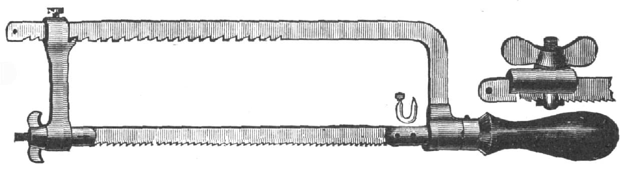
FIG. 206.—SHOWING THE HACK SAW
ADJUSTABLE TONGS.
I lately came across about as handy a blacksmith’s tool as one could wish to find. It was an adjustable pair of tongs that will hold tight enough for any light work. The jaw, J, Fig. 207, is provided with a slot, S, and the rivet is carried at that end in a tongue, A, that passes through a lug, B, and is fastened by a key, K, so that it can be set with the hand hammer and without any wrench. I have found it an excellent tool, and am sure that anybody that makes one will be pleased with it. —By NEW YORKER.
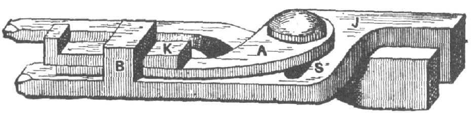
FIG. 207.—ADJUSTABLE TONGS, AS DESCRIBED BY “NEW YORKER”
TONGS FOR MAKING SPRING CLIPS, SLEIGH JACKS, ETC.
I send you a sketch, Fig. 208, of a pair of tongs for making sleigh jacks, spring clips, staples, etc. A is a clip to be bent as at B, Fig. 209. The pair of tongs has in jaw, C, Fig. 210, a hole for the stem, the width of the jaw, D, being that required between the jaws of the clip. If both jaws have holes through them and are of different widths two sizes of clips can be bent on one pair of tongs.—By R. R. M.
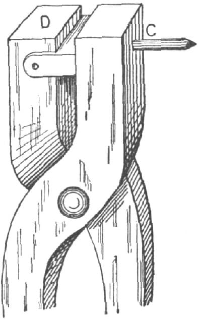
FIG. 208
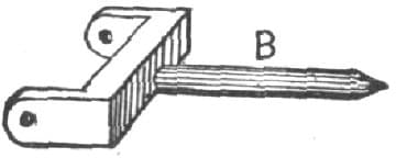
FIG. 209
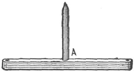
FIG. 210