CHAPTER IV
DRILLS AND DRILLING
Making a Drill Press.
The drill press shown in the accompanying engraving, if properly made, will drill a perfectly straight hole. It will drill from the smallest to the largest hole without any danger of breaking the bit. The lever B, in Fig. 71, is 11/4 × 1/2 inch and five feet long. The part C is 3 × 6 inches. The chain A can be of the length most convenient for the operator.—By R. E.
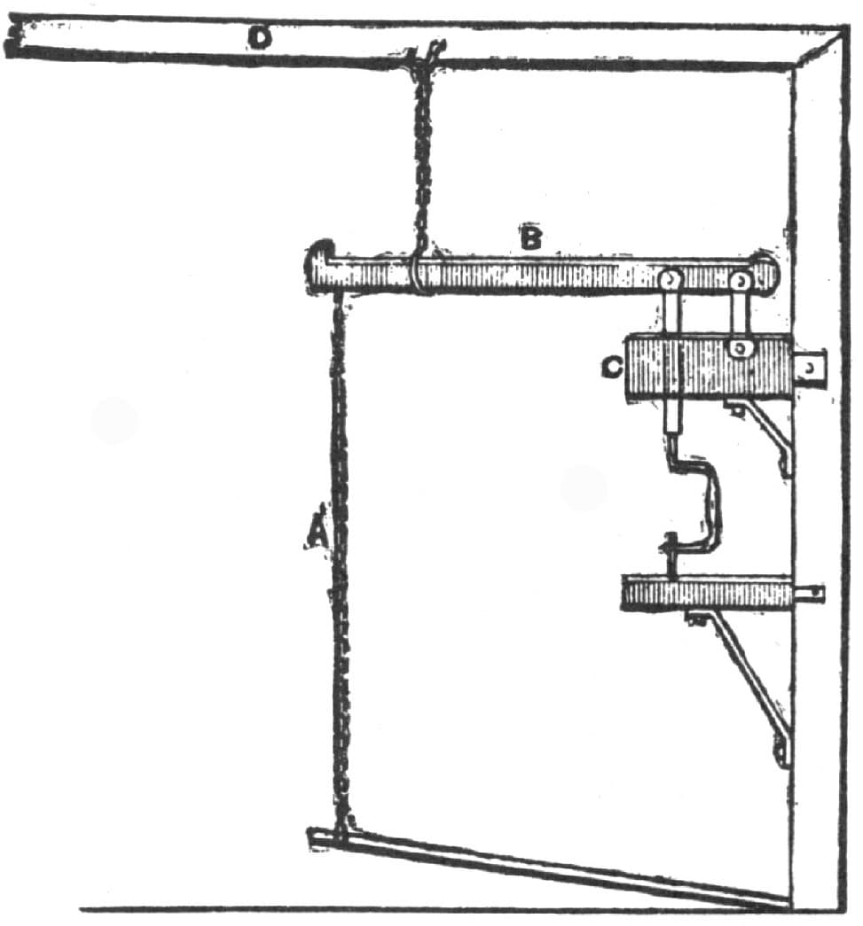
Fig. 71—A Drill Press as Designed by “R. E.”
Drilling in the Blacksmith Shop.
In my shop there is not much drilling done, and what there is done is composed principally of small holes and countersinking for holes 1/4 inch and less in diameter. For this purpose I use an ordinary hand drill, but I have found, as I expect other people have found also, that for larger holes than those above named the breast drill becomes quite a nuisance. It is almost impossible to hold it steady, and it drives entirely too hard. It takes a great deal of pushing to get the drill to feed, no matter how thin the drill point is made. So, as I said above, I discarded the breast drill for all holes over 1/4 inch in diameter. For holes from 1/4 inch up to about 1/2 inch I used the clamp-shaped rest shown in Fig. 72. I made the back of A very much broader than is generally done in such cases, so as to prevent it from bending, a great fault in articles of this kind, as commonly made. I made the work table, T, about 6 inches square and gave the feed screw, S, a much finer pitch than is usual. I employ 12 threads per inch, by means of which I can feed as lightly as I like. I use all square shank drills, and let the end of the shank pass through the socket so that I can knock the drill out easily. This answers very well for holes that are not too deep. A man can stand the work in such cases. For deep holes and those from 1/2 inch in diameter upwards I have a small machine, shown in Fig. 73, which I had made to order. The reader will see that it has no self-feed on it. Inasmuch as the operator has got to stand by the machine and mind the wheel it is just as easy, it seems to me, to put on the feed, and in doing so he can increase or diminish it according to the feel of the drill. In this case, as in the other already mentioned, I made the feed screw, S, with a pitch of 12 threads to the inch, and bushed the feed wheel, F, so that I could put in a new nut whenever the threads wore. I made the cap, C, screw on so that I could easily take it off and put in a washer for taking up any lost motion in the feed screw collar. I bought cut gear, G, for I think every drill should have such gear, because they run so much easier. The drilling takes enough hard work to drive without losing any power through cast gear wheels. I made the driving wheel, W, larger than usual, and fastened the handle, H, in the slot so that I could move it further away or closer to the hub, according to circumstances. Every one of the alterations from the ordinary form here described, I am convinced, are substantial improvements.
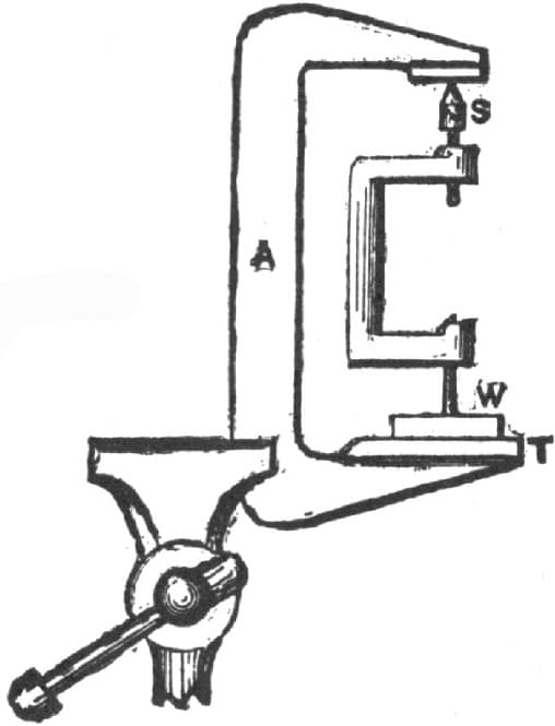
Fig. 72—An Ordinary Hand Drill Improved
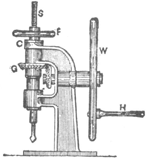
Fig. 73—A Bench Drill
In the course of time work came along that I could not get under the machine last mentioned, and other work came in that required holes too big to be bored in a hand machine at all. For them I had to resort to the ratchet brace. The rig for the ratchet brace I found, as I presume every other one has found who does an odd job, to be a complete nuisance; still, I had no choice. One day, I put a new hand, a repairer I had hired, on a ratchet brace job, and left him at it, going away from my business for two days’ time to see about some other work. When I got back I found he had rigged up what he called the blacksmith’s drill-frame, and which he said was common enough in Scotland, but of which I only knew of one other in this country. I did not like the look of the thing. It appeared like a cross between a gallows frame and some sort of a weighing machine. However, I did not say a word to my man, because I felt a degree of uncertainty about the matter. It might be all right, and so I waited developments. I asked him:
“What, will it drill any better than can be drilled by the method we have formerly used?” He made reply:
“It will drill anything you can get between the posts, and from 1/4-inch hole up to a 2-inch hole or more.
He proved this assertion by drilling first a 1/4-inch hole, and then a 11/2-inch hole, that being the largest drill at hand. For the large hole he used the ratchet brace, using the frame as a feeding fulcrum. Fig. 74, of my sketches, represents the device in question. It has two posts, A, and two posts, B, fast to the floor and ceiling. The fulcrum lever is pivoted at C, and has a feeding weight at the opposite end. The lifting lever is pivoted at D, and has, at F, a link connected to the end of the fulcrum lever. At E is an iron plate for the drill brace to rest against, and G is a handle to operate the lifting lever. The work is rested in a movable, or it may be a fixed bench. The one in question, however, is made movable. By pulling the handle, G, the fulcrum lever is raised, and the drill brace or ratchet brace may be put in position on the work. When G is released the weight pulls down the fulcrum lever to feed the drill brace to its cut. If the weight is too heavy the pressure may be relieved by pulling upon G, or by moving the work further from the posts A, the pressure becomes less, because the leverage of the weight is less. This device has one fault, which is that as the fulcrum lever descends in the arc of a circle, as indicated by H, it may, in deep holes, become necessary to move the upper end of the brace to drill the hole straight in the work. The fulcrum lever may be raised or lowered for different heights of work by shifting the pin C higher, there being holes at A, at intervals, for that purpose. This device may be a very old one. It is certainly good for the purpose, however, and very desirable for use where there is no power drill-machine. I would not be without it for many times its cost.—By BLACKSMITH.
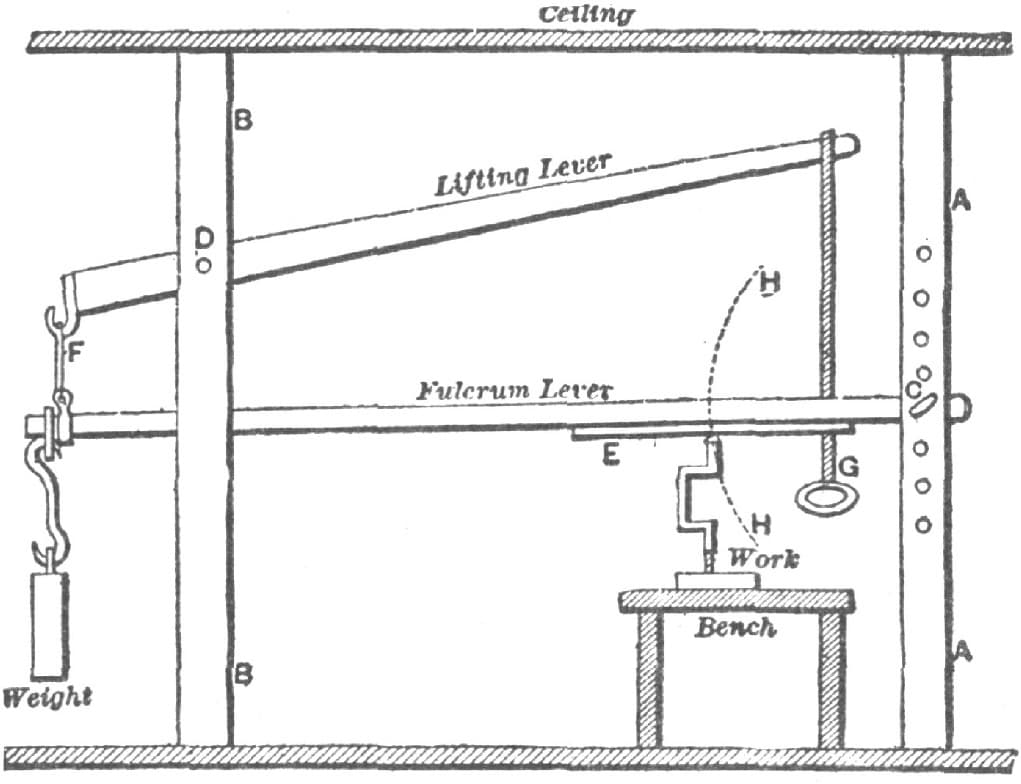
Fig. 74—The Device Invented by “Blacksmith’s” Man
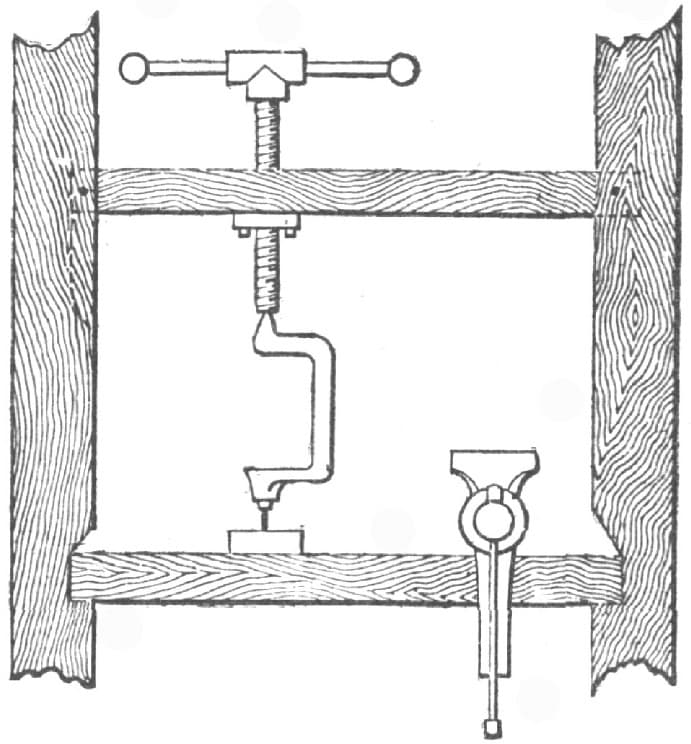
Fig. 75—Simple Drill Press, as Made by Will Tod
A Simple Drill Press.
I send, as shown in the accompanying engraving, Fig. 75, a rig which is simple and also avoids the “arc” direction which has been complained of. A common iron bench screw is inserted in a 4 × 4 scantling, mortised, over the bench, into upright posts. The cut explains itself. The screw (two feet long) may be had for $1.00, or the smith may make one himself, having a hand wheel. This arrangement takes no room.—By WILL TOD.
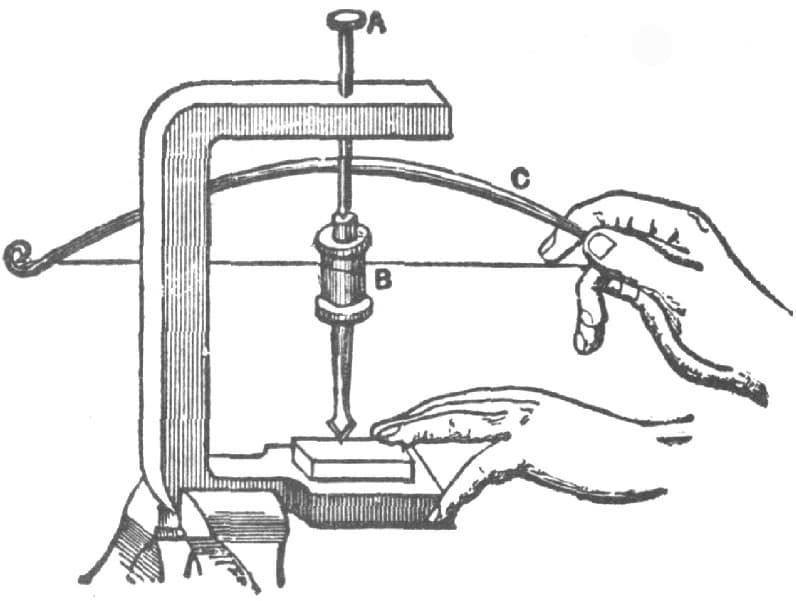
Fig. 76—A Small Drill, as Made by “C. W. D.”
Making a Small Drill.
A very serviceable drill may be made by welding the socket of a shoemaker’s awl into a 3/8-inch rod, 5 inches long, with a countersink at the upper end forming a cup to hold lubricating oil and in which the conical center of the feed screw can work. In the engraving, Fig. 76, A represents the screw and B the spindle. Bore a hole through a block of wood to receive the center of the spindle and put the spindle in a two-centered lathe. Move it with a “dog” and a turn pulley like a common thread spool. The drill is run with a bow C, holding all in a vise. Tempered awl blades make good drill bits.—By C. W. D.
To Drill a Chilled Mold-Board.
If you want to drill a hole or file a notch in a stove plate or ploughshare, or other piece of cast-iron, lay it on the fire level until it is cherry red, and then with tongs lay a bit of brimstone on the spot you wish to soften, the piece of brimstone being a trifle less in diameter than the hole you need. Leave the iron on the fire until cold enough to handle and it will yield to your tools.—By D. T.
Holding Long Bars in Drilling.
A good method of holding long bars of iron, such as sled shoes, so that the holes can be drilled in them easily by one person, is as follows: Take a strong 1/4-inch cord or rope and fasten it to the ceiling about five, six or seven feet from the drilling machine, then fasten a pound nut on the end of the rope and let it reach nearly to the floor. When you wish to drill iron, wrap the rope around the iron once at the height you want and you will find that you will have a very handy tool. You can drive a nail so as to hang it up out of the way when not in use.—By A. W. B.
Drilling Glass.
Stick a piece of stiff clay or putty on the part where you wish to make the hole. Make a hole in the putty the size you want the hole, reaching to the glass, of course. Into this hole pour a little molten lead, when, unless it is very thick glass, the piece will immediately drop out.
Straightening Shafts or Screws—A Remedy for Dull and Squeaking Drills.
Every machinist who has ever attempted to straighten a polished shaft or screw knows the difficulty of marking the point of untruth when the work is revolved on the centers of a lathe. By procuring a piece of copper pointed on one end and of a shape suitable to fill the tool post, and allowing it to touch the work as it turns, a red mark will be left, even on a brightly polished surface, and this will furnish the desired guide for correction, and at the same time if a short piece of octagon steel about 13/4 inches diameter is allowed to partly lie beside the tool post in its T slot, the straightening bar used may be fulcrumed on this with the copper tool still remaining in the tool post, thus expediting the work. If a piece of sheet copper is screwed or riveted to the end of the bar used for straightening, no injury will result to the work from its contact therewith.
Blacksmiths and machinists who use twist drills, have probably been bothered when drilling moderately hard steel by the squeaking and slow cutting of the drill caused by the rapid dulling of its edges. To remedy this, first sharpen the drill, then procure a small piece of tool steel, say 4 inches long, half an inch wide, and 3/16 to 1/4 of an inch thick, and after rounding and tempering one end, place the offending drill in a vise, between a pair of copper clamps, gripping it so that the cutting points will be well supported. Then by holding the tempered point of the tool I have described, against the lips of the drill and striking lightly with a hammer on the opposite end, the lips will be upset so that a good clearance will be secured, and the results will be satisfactory if the operation has been carefully done.
This upsetting will, of course, slightly enlarge the diameter of the drill, but in most cases this will do no harm. —By J. F. ROSS.
A Chinese Drill.
Some time ago I read an account of the high quality of Chinese steel. I think there must be some mistake about it. During five years’ residence in China, I often examined and remarked the inferior quality of their drills, gravers, etc., and I think their best steel is all imported from England, as I know their finer iron is. They have an ingenious arrangement for drilling, which is remarkably rapid. As shown in the accompanying engraving, Fig. 77, the drill is fixed in an upright bamboo, which is weighted by a stone (not unlike an old grindstone), at top. It is attached by strings from the top to a handpiece which slides up and down the lower end of the rod. When the rod is revolved and the hand piece held still, the strings wind on the rod and raise the hand piece, and the machine is “wound up.” To start drilling, press the hand piece down the rod till the strings become unwound by the rod revolving; lighten the pressure and the momentum will wind the machine up the reverse way, when pressure is again resumed.—By WILL TOD.

Fig. 77—A Chinese Drill as Described by Will Tod

Fig. 78—A Drill and Countersink, as Made by C. H. Preble
A Drill and Countersink Combined.
I enclose sketch, Fig. 78, of a tool made by myself last Summer, and which may be of some interest to carriage-smiths and blacksmiths who do tiring.
It is a drill and countersink combined, for use on buggy tires. It can also be applied to drilling and countersinking sleigh and sled shoes. It makes quite a saving in time by removing the necessity for using a drill and a countersink separately.
It is made so that when the drill part begins to go through the tire, the countersink begins to cut, and when the work is countersunk to the proper depth it is stopped by a shoulder on the tool. Any blacksmith can make this tool in a very short time, and after using one he will never go back to the old method.—By C. H. PREBLE.
A Handy Drill.
I have a drill made by myself that is simple, strong, and very effective. Any blacksmith can make it in the following manner:
Take a two-inch rod of iron long enough to reach from the bench to the shop loft, then take two bars of iron, 11/2 by 5/8 inches, and turn good solid eyes on them, as shown in Fig. 79 of the illustration. The pieces should be about three feet long. Then shape them as shown in Fig. 80, the top and bottom pieces being twisted to fit the shaft. Then take a drill brace made as shown in Fig. 81. The top part of brace works as a ratchet. The four eyes on the shaft have set screws to hold them in position. The pieces shown in Figs. 80 and 81 can, by means of the set screws, be easily adjusted to the work to be drilled, and will take in larger work than most drills. The drill stock works the same as a ratchet drill. The bottom side of the top cap should be slotted so as to hold the drill stock in place.

Fig. 79—Showing the Bars with Eyes Turned in them
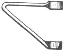
Fig. 80—The Bars Bent
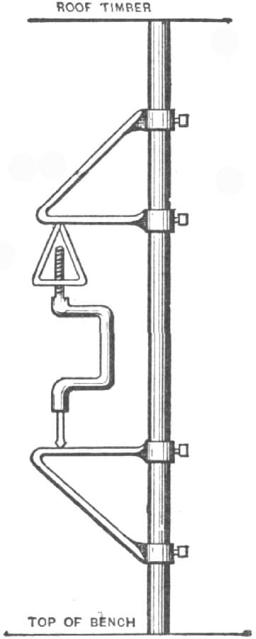
Fig. 81—The Drill Completed
The thread on the drill can be made four inches long or longer as desired. The threads should be cut very coarse so that they will not wear out too soon. Fig. 81 shows the drill completed.
This drill can be used to good advantage on steam boilers and other machinery that cannot be brought into the shop. —By J. W. J.
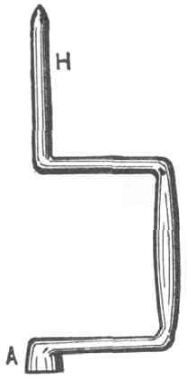
Fig. 82—A Home-Made Drill, showing How the Shank H is Formed and the End A Upset
A Home-Made Drill.
I make a drill brace as follows:
I take a round rod of iron, size 11/4 inches, shape it as shown in Fig. 82 of the accompanying illustration, upset it at A, and make it about 11/2 inches square there. I then punch a hole in this end about the same as if for an old-fashioned bit brace, to receive the drill shank. I then take a flat piece of iron about a foot long, and draw the ends shown in Fig. 83 at B, B. I next take a large nut or a plug of iron 11/2 inch square, and weld it on the flat piece at C, making it 2 inches thick. I then punch or drill a hole large enough to take in the shank H, shown in Fig. 82, and cut a very coarse thread to prevent it from wearing loose. I next weld the ends B, B, together, and the brace is then ready to be put together as shown in Fig. 85. I next take a piece of scantling 4x4, cut a mortise in one end as shown in Fig. 84, and bore a half-inch hole at R, and fasten this scantling over a joist directly over the back of the vise bench. I put a steel plate on the lower end of the piece shown in Fig. 84, and “dot” it well to keep the drill from slipping off. In Fig. 85 the brace is shown completed, L being the joist and S the vise bench. This is a handy and cheap way to make a drill, and answers well in a small shop where room is scarce. This make of drill works on the same principle as the ratchet drill, and can be adapted to heavy or light drilling. As the drill cuts itself loose it can be tightened by turning the ratchet D. It is the best home-made drill I know of.—By J. W. J.

Fig. 83—Showing the Flat Piece Ready for Welding

Fig. 84—Showing the Piece of Scantling Used
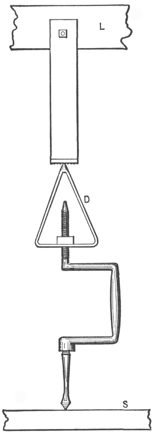
Fig. 85—Showing the Joist, Vise Bench, and Drill
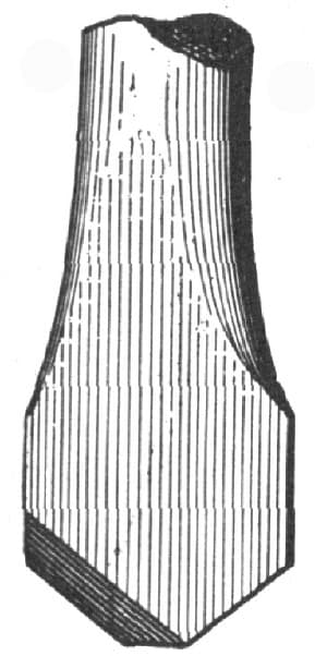
Fig. 86—A Stone Drill as Made by W. O. West
Making and Tempering Stone Drills.
My method of sharpening and tempering stone drills may be of interest to some fellow craftsmen.
First, in making a drill do not draw down the steel, but cut off each side and then upset back to widen the bit, making strong or light to suit the hardness or softness of the stone to be drilled. Next place the drill in the vise and trim off as shown in the accompanying cut, Fig. 86, then lay it down until cool, and then file and temper. Draw the temper twice to a deep blue and you will then have a tool that will drill without cornering a hole, and one that will also stand much better than an ordinary drill.—By W. O. WEST.
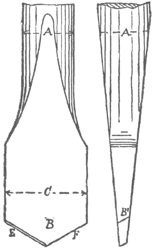
Fig. 87—Form of Drill for Smooth, Straight, or Round Hole
Some Hints About Drills.
To drill a smooth, straight and round hole with a flat drill let the diameter, as at C, in Fig. 87, be enough larger than the shank A to allow the cuttings to pass freely and parallel, to steady the drill in the hole. Let the bevel at E and F be, for iron and steel, just enough to clear well, and for crass, give more bevel, as at B1. To make a drill cut freely on wrought iron or steel, give it a lip by setting the cutting-edges forward as in Fig. 88.
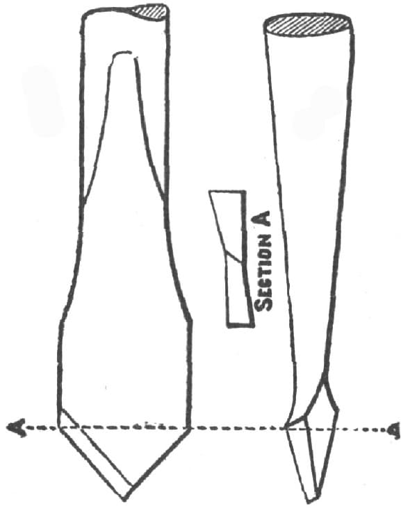
Fig. 88—Form of Drill to Cut Freely in Wrought Iron or Steel
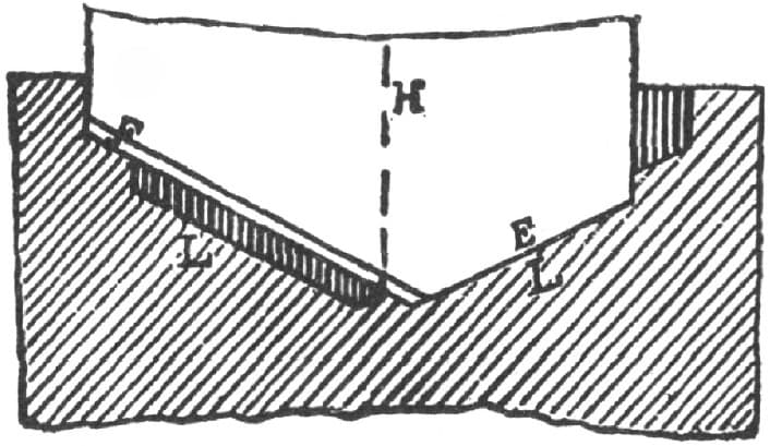
Fig. 89—Showing center of rotation at H
To make a drill drive easily, first be sure that it runs true and that it is ground true. Suppose, for example that the center of rotation of the drill shown in Fig. 89 is at H, and the cutting edges be ground as shown. Then E will cut a certain-sized hole, and F will simply act to enlarge it, so that the rate of feed can only be sufficient for one cutting-edge instead of for two. If the drill be ground to one side, as in Fig. 90—H being the center of rotation—all the cutting will be done by the edge F, and the rate of feed must again be only one-half what it could be if both edges acted as cutting-edges.
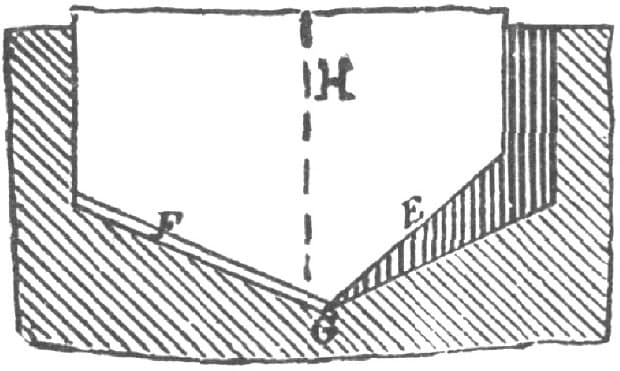
Fig. 90—Shows Drill Ground too Much on One Side
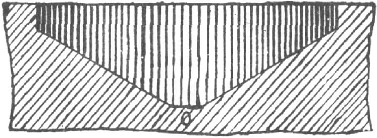
Fig. 91—Showing another Improper Way of Grinding
Another secret in making a drill cut easily is to keep the point thin, so that it shall not cut a flat place at the bottom of the cone, as shown in Fig. 91 at O, which increases the force necessary to feed the drill.
Drills for brass work should have the cutting edges form a more acute angle one to the other than drills for the fibrous metals, such as steel or iron.
Oil should be supplied to a drill when used on wrought iron, steel, or copper, but the drill should run dry on cast iron, brass and the soft metals, such as babbitt metal, tin, lead, etc.; but very hard steel is easier cut dry than with oil.
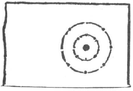
Fig. 92—Showing how to Mark a Piece of Work to be Drilled
For all ordinary work, a drill should be tempered to a bright purple, but for extra hard metal a brown temper may be used.
To drill a hole very true to location, mark it as in Fig. 92, the outer circle being of the diameter of the hole to be drilled, and the smaller one simply serving as a guide to show if the drill is started true. Both circles should be defined by small center-punch marks, as shown, as the oil and cuttings would obscure a simple line.
Drifts and Driftings.
The drift is a useful tool, once extensively employed, which has been pushed aside by improved machinery. Still, as many a country shop is unsupplied with a slotting machine, the drift may often be used with advantage yet. Indeed no other hand tool will cut with precision a small angular hole where there is no thoroughfare; and even where the tools can pass through, if the metal be thick or there be a number of holes to cut, the drift will be more economical than the file.
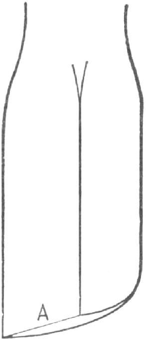
Fig. 93—Showing the Simplest Form of Drift
The simplest form of a drift is a steel plug, as shown in Fig. 93 of the accompanying illustrations. This is used to dress out a square hole, especially one with no thoroughfare. It is driven into the hole, the edge A cutting a chip as it descends. The underside slopes back slightly from the cutting face to allow room for chips when the hole does not go through the metal.
To take a second cut, a thin strip of brass or steel, such as shown in Fig, 94, is inserted behind the drift before driving it again, and further cuts are taken by backing up the drift with similar strips until the hole is cut to gauge.
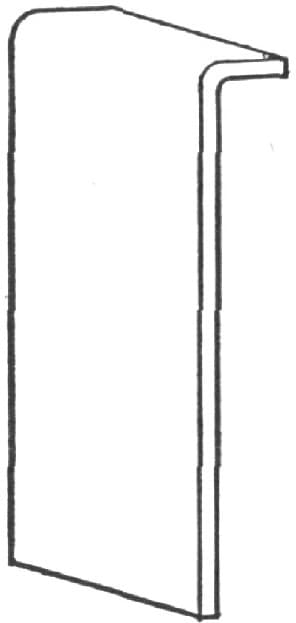
Fig. 94—Showing the Strip used in making a Second Cut
The commonest form of drift is made of a tapered bar of steel, around which teeth—about eight to the inch—are cut with a file, as in Fig. 95. It will readily be seen how a round hole is squared, or a square hole enlarged by driving such a drift through it. The teeth will cut better if filed somewhat diagonally. The tool being very hard, must be fairly struck or it will be liable to break at one of the notches. A round hole can be converted into a hexagonal one in a similar way by means of a six-sided drift, more quickly and much more exactly than by filing.

Fig. 95—Showing the Commonest Form of Drift
To square a round hole with no thoroughfare, in a box wrench for instance, it is first made flat on the bottom, say with a D bit. Then a half round plug is inserted as backing, and a flat drift driven in and gradually fed to the work by strips of brass till half of the hole is cut square. The half round plug is then withdrawn, the drift faced the other way, and the other half of the hole cut, suitable backing being inserted. A half round drift, cutting on its flat face, could be used for this job, instead of the flat one, but would not be so easily backed up and directed.
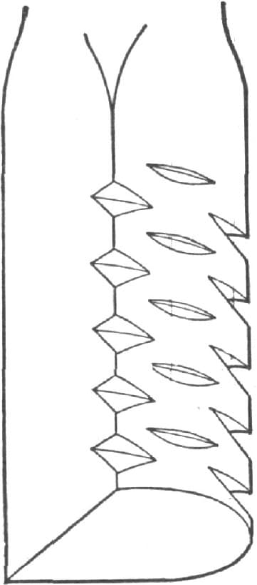
Fig. 96—Showing a Drift used for making Round Holes Oval
Half round drifts, cutting on the round face as shown in Fig. 96, are used to make round holes oval, in hammer eyes for instance. They are backed up first by a half round plug and then fed to the work by slips of brass or steel. In this instance, however, the half round plug must have a shoulder, as shown in Fig. 97, to keep it from slipping through the hole.
These are but the simplest styles of drifting, but they show that the drift can be used to cut almost any shape of hole. —By WILL TOD.
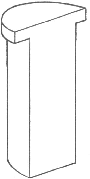
Fig. 97—Showing how the Shoulder is made on the Plug