CHAPTER V
FULLERING AND SWAGING
The Principles of Fullering.
I should like to say a few words about swaging, which will, I think, be of interest to the younger members of our trade if not to the older ones. Suppose, then, that we take a bar of iron, such as B, in Fig. 98, and forge on it a square recess. The bar will get a certain amount longer, and, in the neighborhood of the recess, a certain amount wider also. Just what the amount would be under any given condition is a matter concerning which I am not aware, but it would, doubtless, vary with the shape and size of the bar, and perhaps also with its degree of temperature. I should suppose that the greater the heat the more the metal would spread sideways and the less the bar would elongate, but I may be wrong in this view.
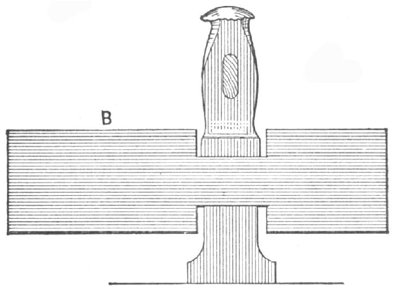
Fig. 98—A Bar in which a Square Recess is being Forged
This is a matter of more importance to blacksmiths than at first sight appears. Suppose, for example, a blacksmith is given a pair of dies to make some drop forgings with; in selecting the best size and shape of bar, the question at once arises as to how much the bar will spread in each direction under the action of the blows.
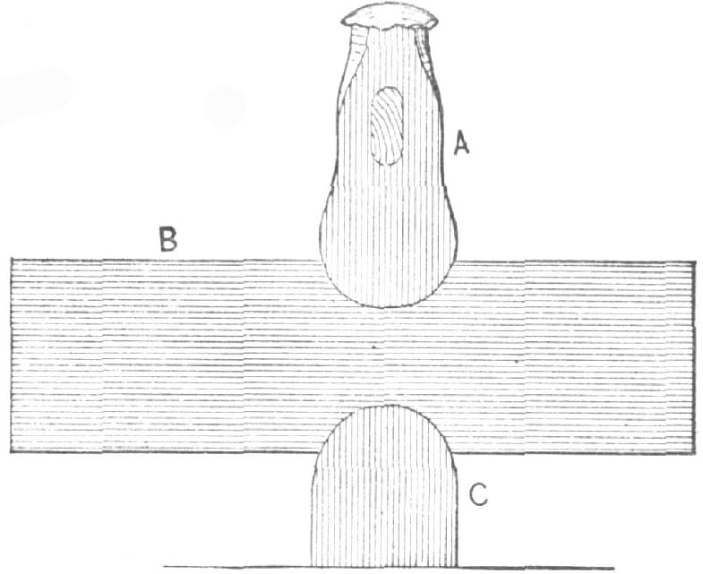
Fig. 99—A Round Fuller Substitute
To take a specific case, suppose we require to forge in a die some blocks of iron that must measure 15/16 inch by 11/16 inch, and be, say, four inches long, there being enough taper on them to permit their easy extraction from the die; now, what would be the best size of iron to use, and how far should it be placed in the die? Would it be better to cut off the pieces, lay them in the die, and let the blows spread them out, or to take a bar, place it a certain distance over the die and depend upon the elongation of the bar to fill the die?
One could, of course, make an experiment for any given job, but it seems to me there could be got from experiments a rule upon the spreading of iron under compressive blows that would be of great usefulness.
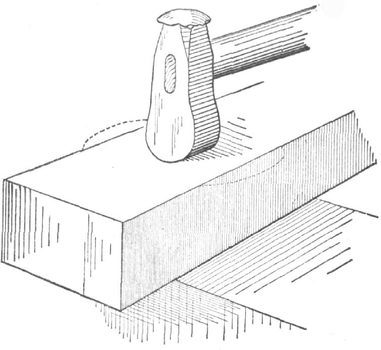
Fig. 100—Spreading a Bar
If, instead of a square fuller, we take a round one, as in Fig. 99, A and C representing top and bottom fullers, and B the bar, the effect is to increase the elongation of the bar and diminish its spread across the width.
If we require to spread the bar as much as possible and increase its width, we turn the fuller around, as in Fig. 100, causing the spreading to occur, as denoted by the dotted lines.
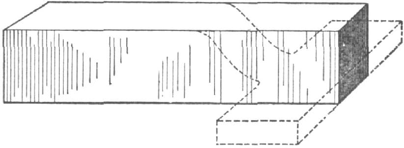
Fig. 101—The end of a Bar to be Forged as shown by the Dotted Lines
Suppose it were required to forge the end of the bar in Fig. 101 to the shape denoted by the dotted lines, the first operation would be to fuller, as at A, Fig. 102. Then the fuller would be applied as in Fig. 103, being slanted, as shown, to drive the metal outwards, as denoted by the arrows.

Fig. 102—The First Operation
Thus the fuller is shown to require considerable judgment in its use, and to be one of the most useful blacksmith tools.
If we were to follow the plan of the scientific men, we could very easily claim that a flatter is simply a fuller, on the ground (as the scientists state with reference to gear wheels and racks) that if we suppose the radius of a fuller curve to be infinite in length, then a portion of its circumference may be represented by a straight line; hence, a flatter becomes a fuller whose radius is of infinite length.—By R. J.
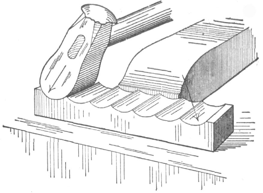
Fig. 103—The Fuller Applied to drive the Metal Outward
About Swages.
The old method of forging a swage was to take a piece of the best quality band iron and roll it up to make the body of the swage, and then weld a face of shear or double shear steel on it, the finished tool appearing as in Fig. 1031/2. This forms a good and durable tool, possessing two advantages: First, that a chisel-rod can be used as a handle, instead of requiring to have an eye punched and a trimmed or turned handle; and secondly, that when the head is worn down a new one can readily be welded on, and the tool need not be thrown away.
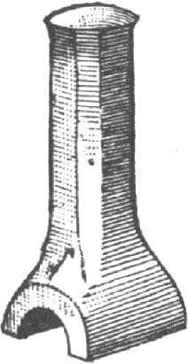
Fig. 1031/2—Old Method of Forging a Swage
In modern practice, however, solid steel swages are employed which, on account of the cheapness of steel and the cheapness of production when made as at present in quantities, obviates to a great extent the necessity for a blacksmith to forge his own tools. A swage for round work may be semicircular, as in Fig. 104, which represents a top swage only, or V-shaped, as in Fig. 105, which shows a top and bottom swage. There is, however, this difference between the two. That shown in Fig. 104 makes a neater and more truly circular job, but is more apt to draw the work hollow than that shown in Fig. 105. The reason of this is that the impact of Fig. 104 is on two sides only, tending to crush the work to an oval instead of closing it to the center, while that shown in Fig. 105 compresses the work on four sides, and prevents its bulging sideways. When iron is compressed on both sides, and liberty is given it to move sideways, the fibers are apt to work one past the other, and a sort of disintegrating process sets in, so that, if the forging be carried to excess on these two sides, without being carried on on the two sides at right angles, the iron will finally split. But if the compression is carried on on four equidistant sides, the forging may be carried to an indefinite extent without separating the fibers, or “hammering hollow,” as it is termed. For these reasons, the form shown in Fig. 104 is used to finish work, and, indeed, is used exclusively on small work; while on large work, under steam-hammers, the form shown in Fig. 105 is used to rough out the work, and that in Fig. 104 to finish with. It is obvious that heavier blows may be used without injury to the iron, while the form shown in Fig. 105 is used, the shape of the working face only being, of course, referred to.
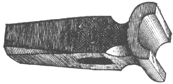
Fig. 104—Semi-circular Top Swage for Round Work
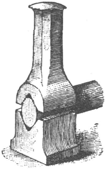
Fig. 105—V-shaped Top and Bottom Swage
On very light work, when the hand-hammer only is used, a spring swage, such as shown in Fig. 106, is often used because the top swage guides itself, and the operator, holding the work in one hand and the hand-hammer in the other, is enabled to use the swage without the aid of a helper.
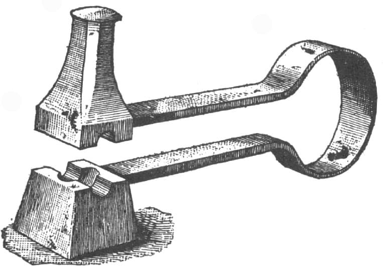
Fig. 106—Shows a Spring Swage for Light Work
Another method of guiding a small swage is shown in Fig. 107, in which the bottom swage is shown to contain a recess to guide the top one by inclosing its outside surfaces.
The holes of circular or round swages are always made of larger circle than the diameter of the work, so that the hole between the two swages, when placed together, will be an oval. This is necessary to prevent the swage hollow from wedging upon the work, and it becomes obvious that in consequence of this form the hollow of the swage must not envelop half the diameter. In practice it usually envelops one-third, or, in large work, still less.
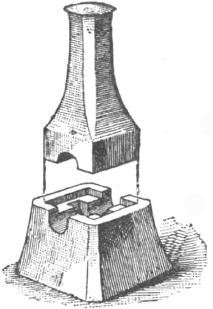
Fig. 107—Recessed Swage
In collar-swages, such as shown in Figs. 106 and 107, the recess for the collar is (to prevent the work from wedging in the recess) made narrower at the bottom than at the top, so that the work may easily be revolved by hand and easily removed from the swage.
Swage-blocks, such as shown in Fig. 108, should have the holes passing through them, as at A, a true circle or square, as the case may be, and parallel for the full length of the hole. But the recesses, B, should be oval, as in the case of hand-swages. Swage-slots, such as shown at C, should, for parallel work, be parallel in their lengths, but taper in their depths, being narrowest at the bottoms of the recesses or slots.
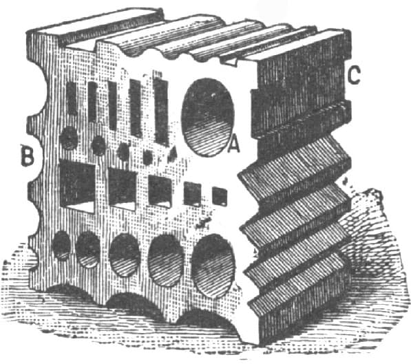
Fig. 108—Swage Block for General Work
Swages for steam-hammers should have flanges on two opposite sides, as shown in Fig. 109, in which B is an anvil block, S a block swage, and S a hand-swage, and this flange should pass below and envelop the angle block so as to prevent the swage from moving the anvil-block when the work is pushed through the swage; and it follows that the flanges should be on the sides of the swage where the swage-hole emerges, or in other words, the length of the flanges should be at a right angle to the working curved face of the swage. The handle, H, of the hand-swage should be below the level of the striking face, S, so that the hammer-face shall, in no case strike it, which would cause it to vibrate and sting, or perhaps injure the operator’s hands.
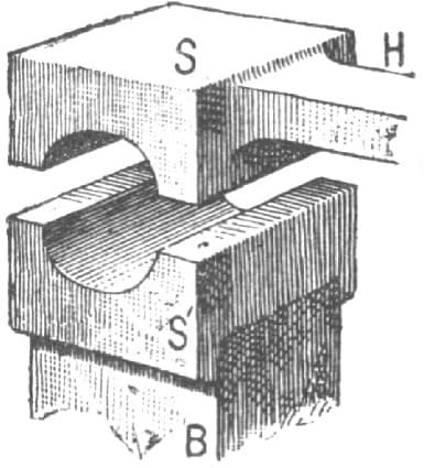
Fig. 109—Form of Swage for Steam Hammers
If the position of the steam hammer or other causes renders it necessary, on account of the length of the work, to have the length of the swage-block run at a right angle to the hammer (as in the case of long work done under a trip-hammer, where the parts of the machine under the helm would be in the way of the work), then the flange must fit the sides instead of the front of the anvil-block, as shown in Fig. 110. For small work intended to be neatly finished under a trip-hammer, hinged stamps, finishing tools or dies are often used. Suppose, for example, it be required to forge pieces such as shown in Fig. 111; then, after being roughed out, they may be neatly and cleanly finished to size and shape in a pair of hinged dies, such as shown in Fig. 112. The curves in the dies, however, require to be of larger radius than those of the work, so that they may not jam the work and prevent it being revolved in the dies. But the depth of the recess in the dies is made correct for the diameter of the dies, so that when the faces of the two halves of the die meet the work will be of correct diameter. To free the dies of the oxidized scale falling from the forging, a supply of water is necessary, otherwise the scale would drive into the work-surface, making it both rough and hard to cut. Sometimes, instead of the pivoted joint, P, Fig. 112, the ends are composed of a spring similar to that shown in Fig. 106, which enables the flat faces of the dies to approach each other more nearly parallel one to the other.
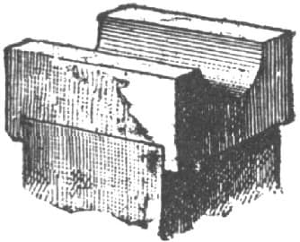
Fig. 110—Another Form of Swage for Steam Hammers
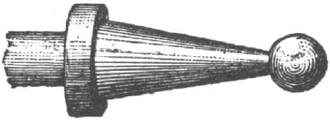
Fig. 111—Specimen of Forging
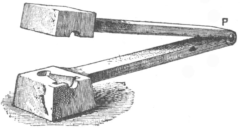
Fig. 112—Hinged Dies for Forging Fig. 111
Rules for Swaging.
To make a good jump weld it requires good judgment on the part of the smith in getting the two pieces fullered properly before welding. Many smiths do not think or use good judgment when making a weld of this kind. To make a jump weld for a shank, carriage-step, or for any other purpose, proceed as in Fig. 113. Fuller at C, upset the shank A, as at the projecting parts, X, X. The shank, A, at X, X, is the important point to take notice of when making the weld. Always let the shank, A, extend over the fullered part, C, as at X, X. This will give you a good chance in using the fuller when welding so as to get the scarfs, X, X, solid to the part B. Never fuller the part C, or forge the part A, as is shown in Fig. 114. If you do, you will not get a solid weld. To make a neat as well as a strong job, finish as is shown at P, P, in Fig. 115. Never finish as is shown at H, H, in Fig. 116. A weld made as at H, H, in Fig. 116, is not as strong as if made as shown in Fig. 115.—By NOW AND THEN.
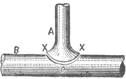
Fig. 113—Correct method of Fullering or Swaging
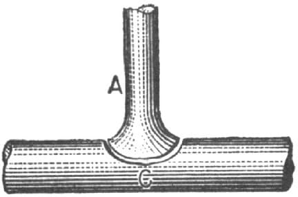
Fig. 114—Incorrect Method
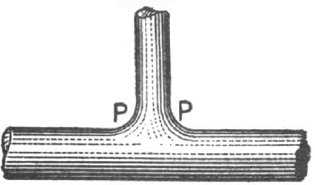
Fig. 115—Correct Way of Finishing
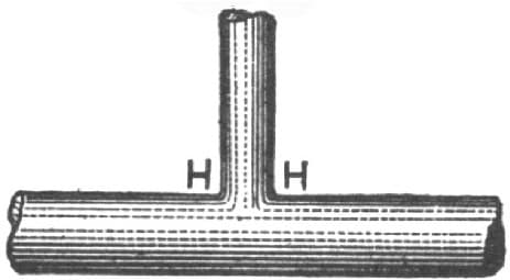
Fig. 116—Incorrect Way of Finishing
A Stand for a Swage-Block.
A blacksmith of my acquaintance once abused the swage-block because he stubbed his toes against it. I want to tell him and others how to save their toes and the swage-block, too.
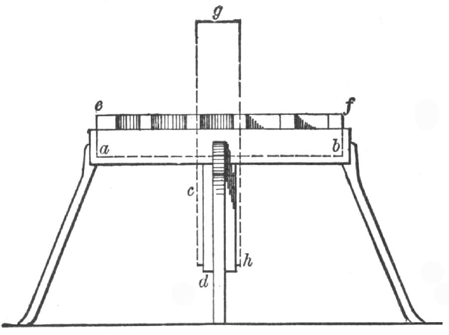
Fig. 117—Stand for a Swage-Block
Let him make a stand for it with four legs, like Figs. 117 and 118, shown herewith. Fig. 117 shows the block, e, f, lying flat, resting on the ledge shown by the dotted line, a, b. The dotted lines, g, h, show how the block would stand when upright in the stirrup, c, d. Fig. 118 shows the side of the block when upright.—By WILL TOD.
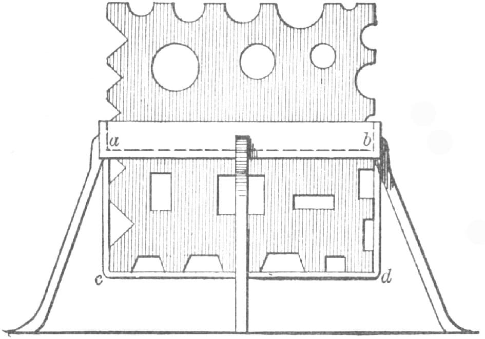
Fig. 118—Showing the Side of the Block when Upright