CHAPTER V
FORGING IRON
Hand Forgings.
Notwithstanding the working of iron is one of the oldest mechanical occupations, the opinion prevails that the blacksmith need not of necessity be a man of much skill beyond what is necessary to heat and pound iron into shape. Yet this is but a small part of the duty required of him. If he is to work metal intelligently he must know the nature of the different kinds, its adaptability for specific uses. One grade of iron is well suited to one class of work and unfit for another. Then, too, welding is something more than the causing of two pieces of iron to adhere. Unless fusion is perfect the work is not well done, and perfect fusion can be obtained only by the proper heat and fit condition of the surfaces. Tempering steel is an important part of the business, and one which few thoroughly understand, or even care to.
In all other departments of carriage-making, patterns can be used with a certainty as guides, but the blacksmith has a large part of his work to do without patterns of any kind other than as general outlines for forms. Beyond this the eye must guide him, and as his work must be performed while the iron is hot, he must act promptly, and unless he is accurate his work must be done over again.
In ironing a carriage the woodwork is placed before him in pieces, and to perform his work well he must decide upon a general line of action before beginning his work. It will not do for him to make one piece and then take up another without previous study. If irons are to be fitted to the wood they must be shaped on the anvil, not on the wood, where, between burning and hammering, the general shape is obtained, but at the expense of the timber. Notwithstanding all that has been written and said against fitting iron to timber by burning, a large percentage of ironworkers in the country never think of any other way. We go into shops and see the blacksmith heat his tire red-hot, place it around the rim of the wheel, and amid fire and smoke “set up” to the rim, while two or three boys are busy with pails of water cooling off the iron. Those who have profited by experience and study find that if the tire is welded to the right length, and bent true, very little heat is required to expand the tire large enough to allow its being placed outside of the felloes, while water poured against the tread of the tire will cool it. In fact, not a few set light tires without using any water, and those who heat the tire but little find that the work is far better than when heated to a point that will burn the wood.
Too many blacksmiths are satisfied if the work is done so as to pass, regardless as to details and accuracy. These men are a disgrace to their vocation, and they too often regulate wages to be paid, and as the number increases more rapidly than that of the good workman, they will interfere the more seriously with wages in the future.
The young man who thinks of learning the blacksmith trade should first learn whether he is physically fitted for the peculiar labor. If satisfied on that point, he should immediately begin a course of study with special reference to the working of metals. He should also study free-hand drawing. Every hour spent at the drawing-board is an hour shaping irons, as he is training the hand to perform the work and the eye to see that it is true. And at no time should he drop the pencil. He should keep in mind the fact that the most skillful are the most successful. We do not mean skillful in one line only, but in all. The man who can direct, as well as execute, is the one who will make the greatest advancement, and to direct it is necessary to know why a thing should be done as well as how.
The poetry of the blacksmith shop has been a theme for writers for centuries, but there is little poetry in it to the blacksmith who stands at the forge day after day pounding and shaping unless he has studied, and finds new themes in every heat, spark, or scale. If he can create beautiful forms in his mind, and with his hands shape the metal to those forms, then he can see poetry in his work. If he is but a machine that performs his work automatically, the dull prose of his occupation makes him dissatisfied and unmanly. —Coach, Harness and Saddlery.
Making a T-shaped Iron.
If the blacksmith who wants to learn how to make a T-shaped iron, will take good iron two-thirds as long as his head block, twice as wide and one-eighth of an inch thicker than he wants the plate when finished (or perhaps one and one-sixteenth inches on a light plate), fuller in one edge one-third from the end, draw off the short end, next split the long end down to within one and one-quarter inches of the fuller scarf (if he has an inch perch), then rest the fuller scarf on the round edge of the anvil, follow the chisel down with the small fuller and punch, and turn off to a right angle with a hand hammer, his iron will be so nearly finished that he will understand what else should be done without any more directions from me.

Making a T-shaped Iron. Fig. 128—Showing the Iron ready for Turning
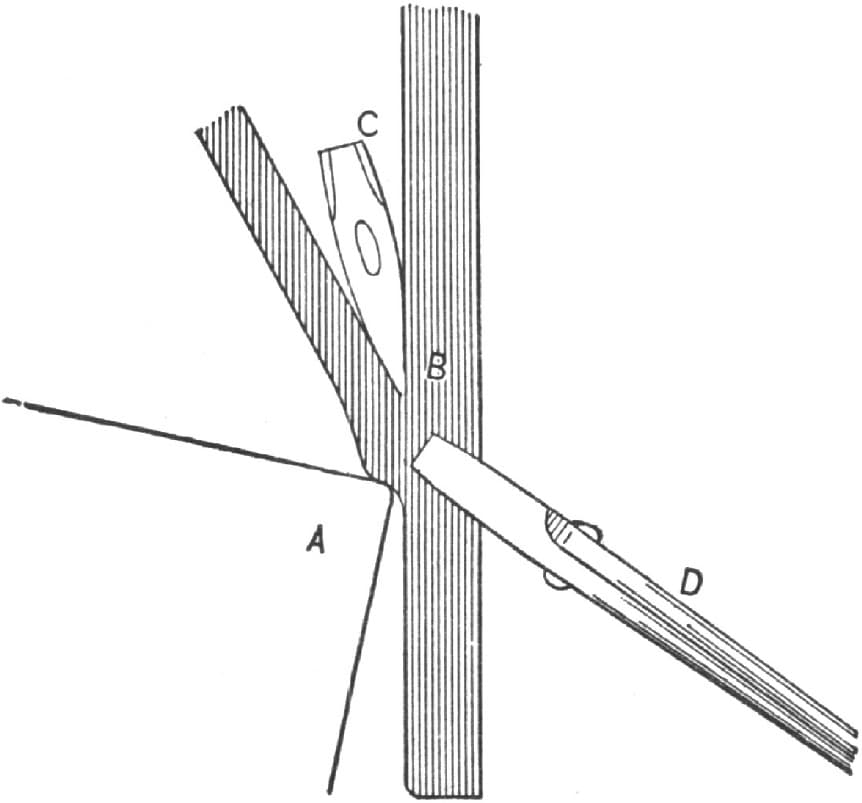
Fig. 129—Showing the Turning Process

Fig. 130—Showing how the Iron is turned to a Right Angle
The accompanying illustrations will help him to understand my instructions. Fig. 128 represents the iron ready for turning; Fig. 129 shows the turning process, A denoting the anvil, B the iron, C the fuller, and D the tongs. In Fig. 130, A denotes the anvil, B the iron, C the hammer, and D the tongs. —By E. K. W.
Another Method of Making a T-shaped Iron.
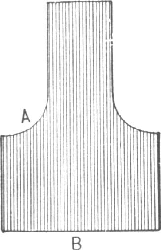
I will describe my way of making a T-shaped iron without having a weld at the hole that the kingbolt goes through. Take a piece of good iron of suitable size for the job you want and fuller and draw out the end as at Fig. 131. Next place B on the anvil and insert the fuller on the two inside corners so as to draw out the ends for the head block, then weld to each end to make it the desired length. Do not cut the inside corners square, but leave them rounding, as Fig. 132, and also a trifle thicker at the center, as this makes it stronger and at the same time gives more support to the kingbolt. I almost always weld at A, Fig. 132, by upsetting well, so as to have plenty of stock, and being careful to get a clean heat. I do not remember ever having one break that was made in this way.—By J. L.
Making a T-shaped Iron by the Method of “J. L.” Fig. 131—Showing how the End of the Iron is Fullered and Drawn Out

Fig. 132—Showing the T Completed
Forging Stay Ends and Offsets.
To make stay ends I take a piece of good iron 11/2 × 1 inch and fuller and forge as shown in the dotted lines of Fig. 133. It will then be shaped as in Fig. 134. I then fuller and forge as in the dotted lines of Fig. 134, and finish with the file. To make a stay offset take a piece of iron 11/2 × 3/4 inch, forge as in dotted lines of Fig. 135, punch a hole and split open. Next open as in Fig. 136, and forge as seen in the dotted lines, then straighten up and finish with a file. Figs. 137, 138 and 139 illustrate another way of making stay ends. Forge a piece of iron, square and small enough to go in the square hole of the anvil; then forge on the flat head, giving a shape as in Fig. 137. Next fuller out and forge as shown in the dotted lines of Fig. 138. This will give a shape as in Fig. 139; then bend according to the dotted lines in that figure, and finish with a file. Figs. 140 and 141 show the finished end and offset.—By J. C. H.

Fig. 133—Showing the Stay End with Dotted Lines for Forging and Fullering
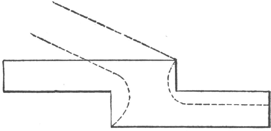
Fig. 134—Showing the Piece as Forged and Fullered

Fig. 135—Showing the Stay Offset with Dotted Lines for Forging
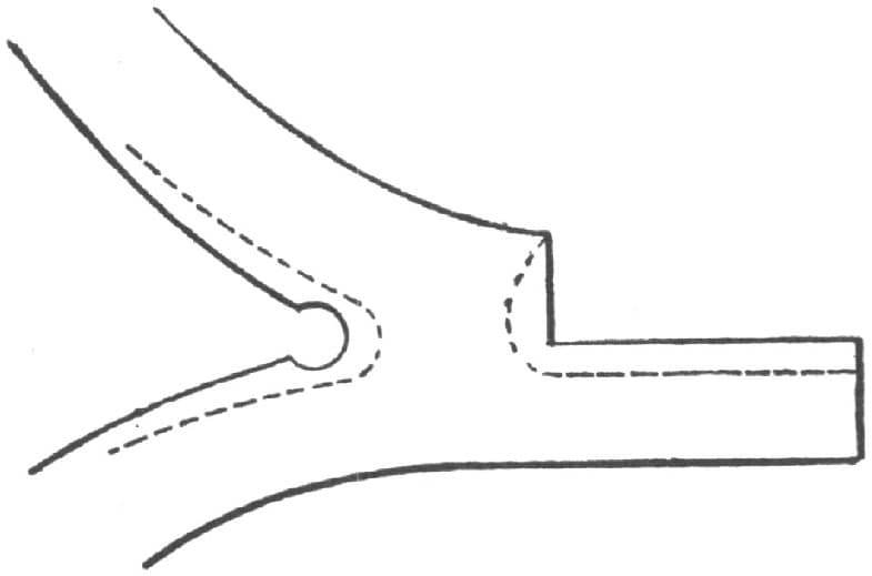
Fig. 136—Stay Offset Opened to Forge as in Dotted Lines
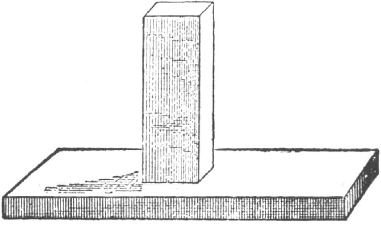
Fig. 137—Showing another Method of Making Stay Ends
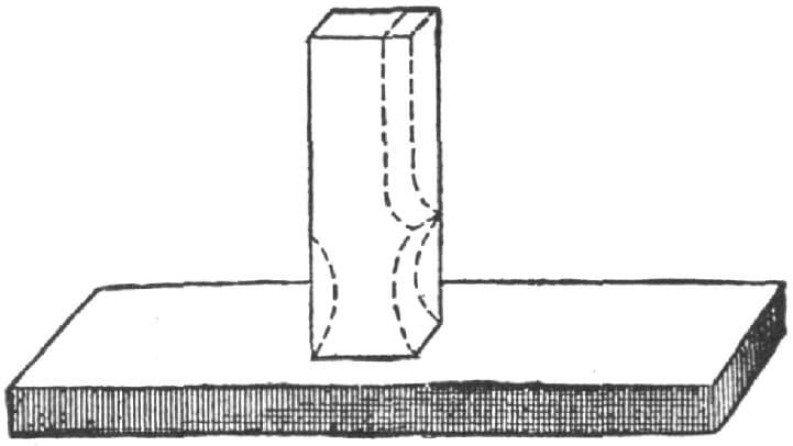
Fig. 138—Showing the Fullering and Forging as by Dotted Lines
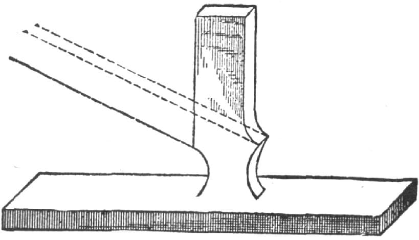
Fig. 139—Showing the Shape after Fullering and Forging
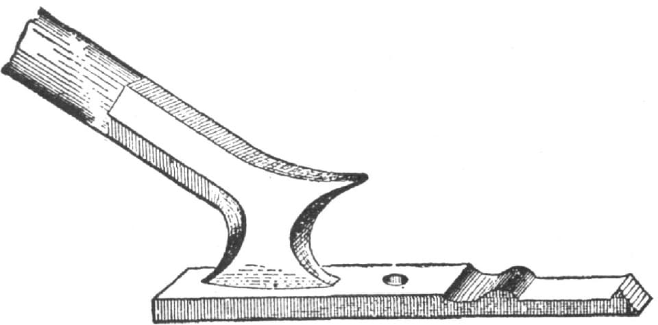
Fig. 140—Showing Finished Stay End

Fig. 141—Showing Finished Offset
Making an Eye-Bolt.
The accompanying illustrations represent my method of making an eye-bolt so that it will be round in the eye, and likewise very strong at the weld.
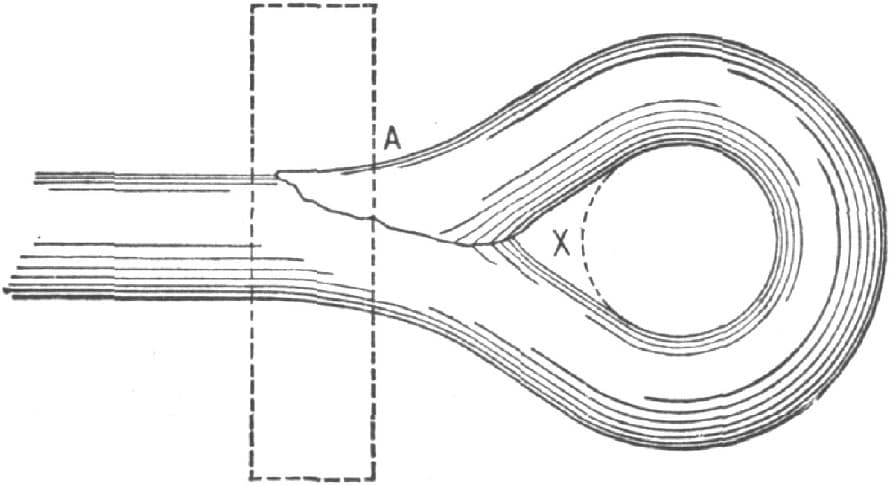
Making an Eye-Bolt. Fig. 142—Showing the Old Way of Doing the Job
Fig. 142 represents the old way of making an eye-bolt and the way it is made now by most blacksmiths. The bolt is simply turned about, the end weld being at A. It will be noticed that the place X is not filled out with iron, and that the hole in the bolt cannot be round unless more iron is used.
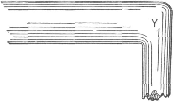
Fig. 143—Showing how the Iron is Turned in E. K. Wehry’s Method of Making an Eye-Bolt
By my method the iron is turned down as at Y in Fig. 143. It is made somewhat flat at Y and then turned around as in Fig. 144. A good weld is made at C, and it is worked down to the size of the iron. The eye-bolt is as shown in Fig. 145. The weld will not give and the hole is a round one. With a little practice, this eye-bolt can be made as easily as the old style, and can be worked down so that it will fit in a hole up to the eye as shown in Fig. 145 at K. Compare this fit with that shown in Fig. 140.—By E. K.
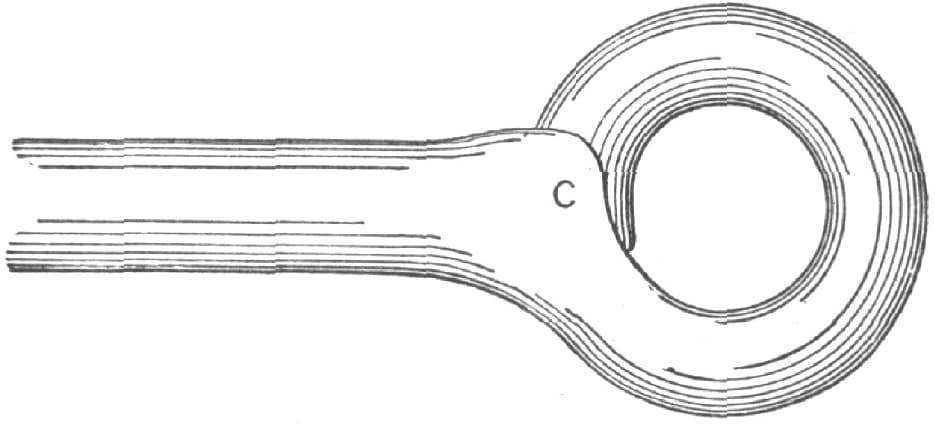
Fig. 144—Showing how the Weld is Made
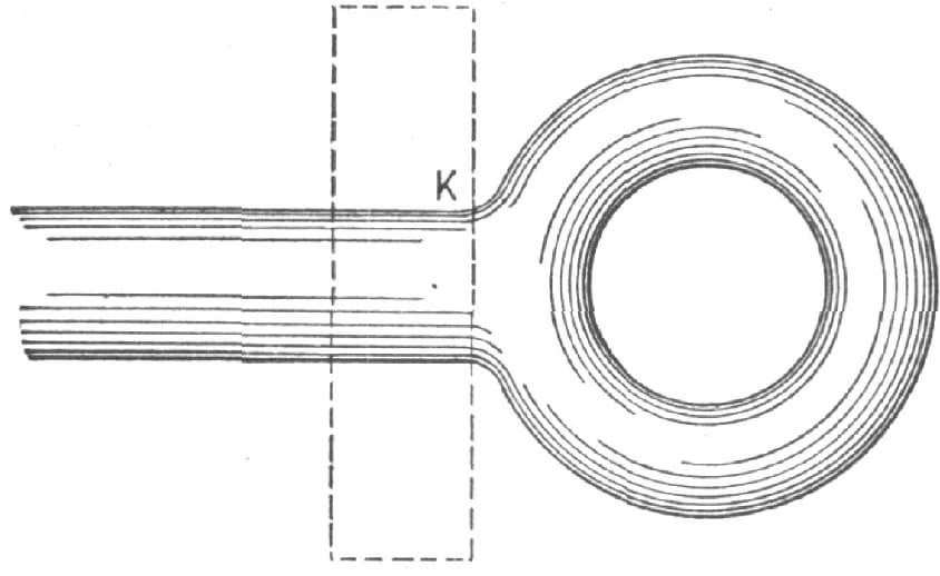
Fig. 145—Showing the Eye Bolt Completed
Forging a Turn-Buckle.
In forging a turn-buckle, I first make a mandrel, as shown in Fig. 146. The part A is one and one-fourth inch round, B is one and three-fourths inch square. I next take some 11/4 × 11/2 inch iron, make collars and weld them on the mandrel, and scarf on each side of the collars, with a round pene fuller for the cheek pieces, as shown in Fig. 147. I then take for the sides some 7/8 × 11/8 iron and cut long enough for both sides, bend in the middle and scarf the ends, and am now ready for welding up. I put one of the collars between the two prongs and take a light heat to stick them together. I then go back to the fire and get a good soft heat, weld down on the mandrel, finish off with the swage, then cut the end and repeat the process. If the turn-buckle is to be finished up extra nice, you can use the same swage for the sides.—By “TINKER.”

“Tinker’s” Method of Forging a Turn-buckle. Fig. 146—Showing the Mandrel

Fig. 147—Showing the Finished Buckle and Collar
Forging a Turn-buckle.
My method of forging a turn-buckle, say for a one and one-fourth inch rod, is: First, I take a piece of one and one-fourth inch square iron and bend it into a ferrule such as is shown in Fig. 148 and then weld into it a prong as in Fig. 149. Then I cut out a place, as at A in Fig. 150, and weld in the other prong. Next I put in a mandrel and shape it up to the taper, as in Fig. 151. This makes half the turn-buckle and by repeating the operation I get two of these pieces, which I weld together at B B, and get the finished turn-buckle as in Fig. 152. In welding the prongs together to join the two halves, I take one-half and let my helper put in the mandrel with one hand and tap lightly with a small hammer with the other, and after the welding is done I use the mandrel to handle the forging with while swaging it to finish.—By SOUTHERN BLACKSMITH.
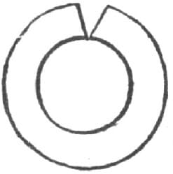
Forging a Turn-buckle. Fig. 148—End View of Ferrule Bent for Welding

Fig. 149—Showing Prong Welded to Ferrule

Fig. 150—Piece cut out at A for Second Prong

Fig. 151—Showing Second Prong Welded and Taper Forged

Fig. 152—Showing the Two Pieces Welded at B B, and Job Complete
Making a Cant-Hook.
I make a great many cant-hooks. For the clasp I use 11/2 × 11/2 inch Norway iron. About half an inch from the end I cut it half off, bend over and weld, forging rather thin inside of the shoulder. I then take a set hammer and make the shoulder for the hook to strike against.
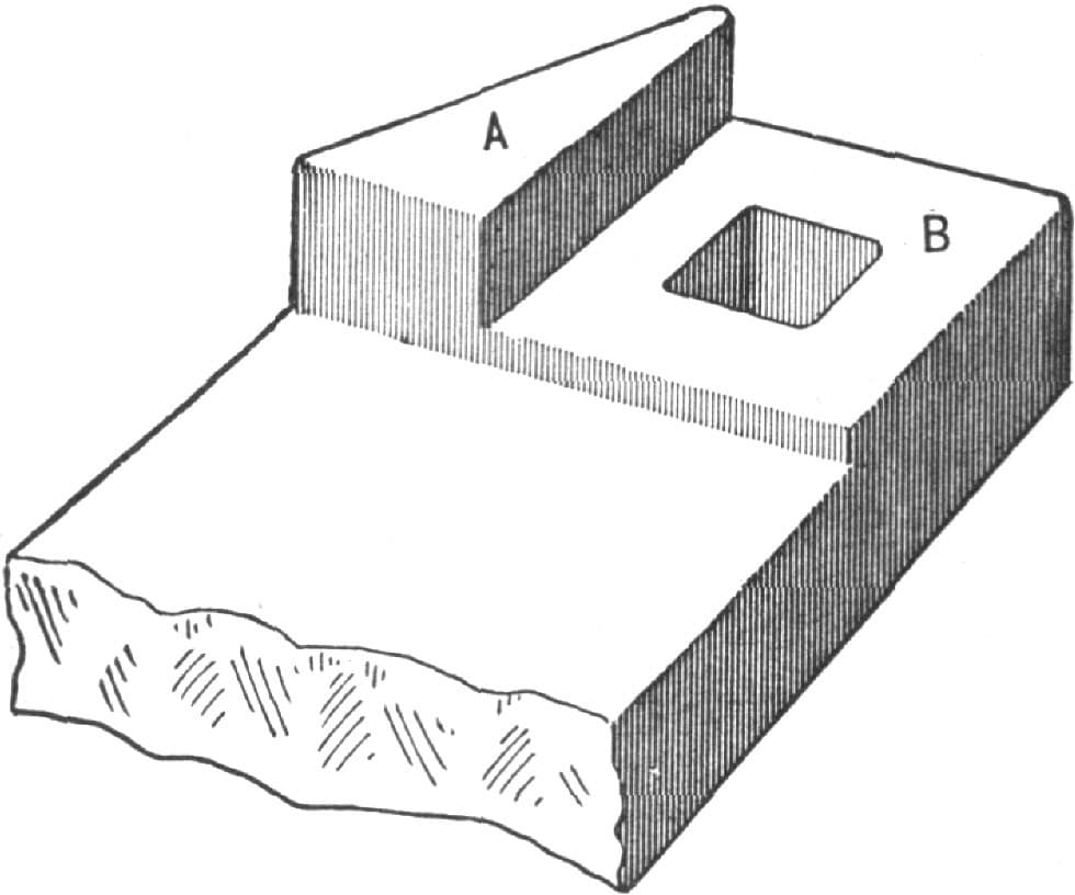
Making a Cant-Hook. Fig. 153—Showing how the Jam and Clasp are Made
I leave the jaw about three-eighths inch thick, punch the hole, and trim to suit. The other end is made in the same way. For the hook I use 3/4 × 1/2 × 7/8 × 1/2 inch steel, cut thirteen inches long. One end should be stove (not bent) and put in the heating tool to get the bill. After taking it out I draw it to a point, punch the hole and bend nearly to a circle. In bending I lay the bill and eye on a straightedge or board as shown in Fig. 154.
I use three bands, the first and second being one and one-half inch No. 14 band iron; the third band is two and one-half inch No. 8. For the pick I use seven-eighths inch square steel, and cut it off ten inches long.

Fig. 154—Showing how the Bill and Eye are Bent
In Fig. 153 of the accompanying illustrations A indicates the thickest part of the clasp, and B is the jaw. This is generally made too thin. The point must not come down far enough to touch the toe ring, but should stand up six inches. In bending the bill there is no sharp corner made which may break the hip when you are pulling it out of a log.—By H. R.
How Forks are Forged.
The following is a description of the manner of forging a four-tined manure fork, as practiced in one of the largest establishments in the neighborhood of New York City. The process of splitting and bending as here described may be extended so as to include forks of a larger number of tines.

How Forks are Forged. Fig. 155—The Blank
The blank for a four-tined manure fork is simply a rectangular piece of mild steel, as indicated in Fig. 155. It is five and three-quarter inches long, one and three-quarter inches wide, and one-half inch thick. The first operation is to draw out the end, leaving a projection, A, as shown in Fig. 156, from which the stem for the handle is subsequently drawn. The piece is then split to the line B, Fig. 157, and is opened out as in Fig. 158. The thickness is reduced to C. All this is done at one heat, and the splitting and opening out is accomplished by a machine termed a splitter. The next operation is to split the piece along the lines DD in the engraving. The parts are then opened out as in Fig. 159, EE, forming, when forged out as in Fig. 160, the middle tines. After the tines EE are drawn out, the ends FF are drawn and bent around as shown in Fig. 161. The last operation is to draw out the handle A to the required shape. After these several steps have been taken, the tines are formed to proper shape and finally are tempered.

Fig. 156—First Operation, Preparing the Handle Stem

Fig. 157—Splitting the Piece Preparatory to Opening it, as Shown in the next Illustration

Fig. 158—The Piece Opened Out, Forged Down and Split Again
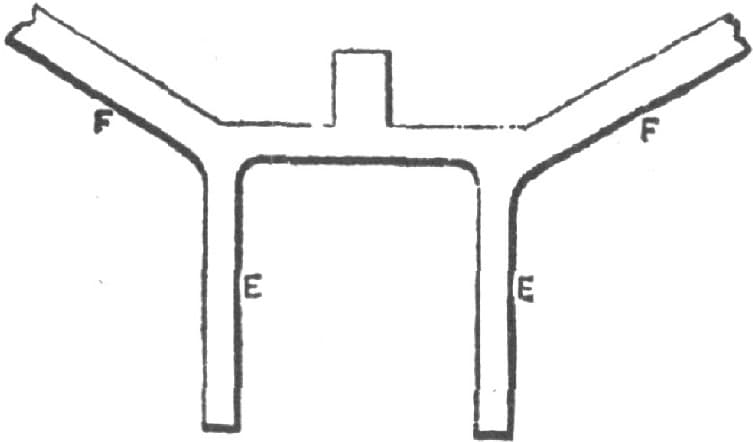
Fig. 159—The Four Tines Roughly Formed
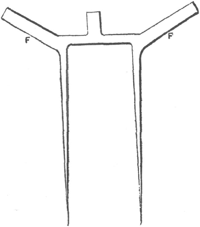
Fig. 160—The Middle Tines Drawn Out

Fig. 161—The Finished Fork
It will be obvious to the practical reader that the grain of the steel in this process of forming the fork is kept lengthwise of the handle as well as of the tines. The whole of the forging operations described are performed under the trip hammer, but the forming or setting to shape of the tines is done in a special machine.
Five Methods of Making one Forging.
The sketches given herewith are of a piece of forging of a somewhat intricate character. The different methods of accomplishing the same result form an interesting study. Fig. 162 shows the finished article.
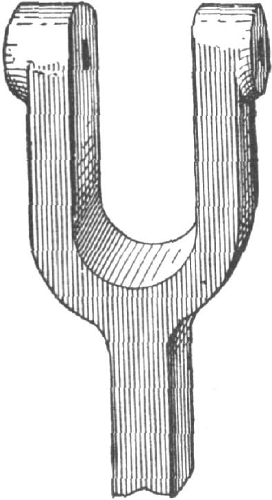
Fig. 162—The Finished Forging

Fig. 163

Fig. 164

Fig. 165

Fig. 166
To make this, says one blacksmith, of ordinary refined iron, I fuller it as at A A, and punch the hole at B, Fig. 163. Then I split it open, as shown by the dotted line in Fig. 164, and open it out as in Fig. 165. Then I bend each arm, as C D in Fig. 165, to shape and forge it to size, punching the holes toward the last. I know of no better way of forging it out of solid iron unless I could get the job roughed out to any better shape by sending it to a shop having a trip hammer to rough the blocks out. Or it might be a good plan to use lighter iron, forge the piece in halves and weld them as shown in Fig. 166, as my principal difficulty is in setting the jaw back for the curve A in Fig. 166.—By YOUNG BLACKSMITH.

Fig. 167
METHOD NO. 2.
Take a piece of iron large enough, and bend it to U shape, as at A, Fig. 167. Cut the end as at mark B, and bend over and weld to make eyes, D. Then jump-weld the rod E. It will make the smoothest job to jump it, if the iron is thick enough.—By H. B.
METHOD NO. 3.
Thinking it a duty, as well as a pleasure, to help my brother blacksmiths, I give you my way of doing the job.
I should take iron of sufficient size to forge the piece A, Fig. 168, fullering it in the center, as at a, with a large fuller to sufficient depth to make a good weld. Then, with a small one, fuller it out on each side, as at bb, and draw it out long enough to bend to the required shape, leaving a lump, CC, on each end to form the eyes. Then forge the stem B, making the scarf at ee; overlap the fullering at a, and more curved than the fullering at a, so that when the jump-weld is made, the stem B will first meet the piece A at the bottom of the fullering at a, and the rest of the surface will come together with the first jumping blows. This is quite important in obtaining a good, sound weld, as it forces out the air and any loose cinders, etc., that may not have been cleaned off the surfaces. After welding at the center by striking on the end, D, of the stem, weld with a fuller applied at ee, and then bend to the required shape.

Fig. 168
There is another and similar way, as follows: Form the two pieces as in Fig. 169, leaving it thick enough to weld and finish. In this case, also, the fullering on the stem must be more flat than the seat on which it welds, so that it will be sure to weld in the center first, and weld on the horn of the anvil.—By G. B. J.

Fig. 169—Method No. 3
METHOD NO. 4.
First take a piece of iron thick enough to give plenty of iron when fullered at A in Fig. 170, and fuller it hollow there. Then bend it to shape; take a piece for the stem and jump it, taking care that it well laps the fullering at A, and let it be more curved than at A, so that it will weld in the center first. To weld, place the hook on the anvil horn, clean it with a brush; bring the stem down on the anvil with a light blow to clean off the dirt, etc.; brush it quickly, strike a few quick blows with a light sledge on the end of the stem and then fuller round the stem. Get a good heat and don’t lose a second’s time and you’ll have a good, sound, neat job.

Fig. 170—Method No. 4

Fig. 171—Method No. 5
Some blacksmiths make the weld round at A instead of hollow, but I don’t see why.—By LEATHER APRON.
METHOD NO. 5.
I would like to have blacksmiths try my method, as per Fig. 171. Forge two separate pieces, as B, C, in the figure, and weld them at D. Fuller A A to dotted lines, and draw out the stem.—By C. A. S.
Making Offsets.
Take a piece of good iron of the proper size and fuller in half way at A, in Fig. 172, then swage down the end B, then split with a sharp chisel at C, down to D. Next with a small fuller work in at D and finish with a large fuller, then turn off the ends E and F, and swage down to proper size as shown in Fig. 173.—By J. D.

Making Offsets. Fig. 172—Showing how the Iron is Fullered and Split

Fig. 173—Showing the Offset Completed
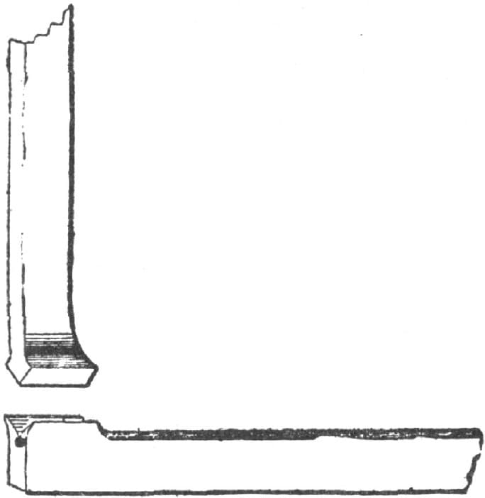
Making a Square Corner. Fig. 174—Ready for the Weld
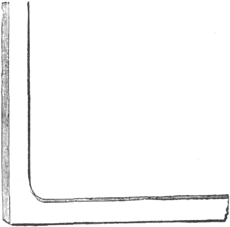
Fig. 175—Completed Job
To Make a Square Corner.
It requires years of hard study and practice to attain any high rank in our profession, but if brother blacksmiths would each make known a little of what they have learned by practical experience, it would be a great benefit to the trade.
I have never met any man who had nothing to learn in blacksmithing, and yet I have known some very good workmen.
The illustrations herewith show a good way of making a square corner, with a fillet inside if required. The upset and scarf are as seen in Fig. 174, and Fig. 175 represents the corner complete.
This works well in heavy iron, say two inches by four inches. It is a V weld in the corner. Be careful to have good clean heats.—By R. C. S.
Making a Square Corner.
I send you herewith my method of getting a square corner up sharp. In the accompanying illustration I show in Fig. 176 a piece of iron to be bent to a right angle and have a square corner. First I cut it half way through where the bend is to be, as at A, then I bend it as shown in Fig. 177, and then weld in a piece B, which brings the corner up sharp and square as shown in Fig. 178.—By SOUTHERN BLACKSMITH.
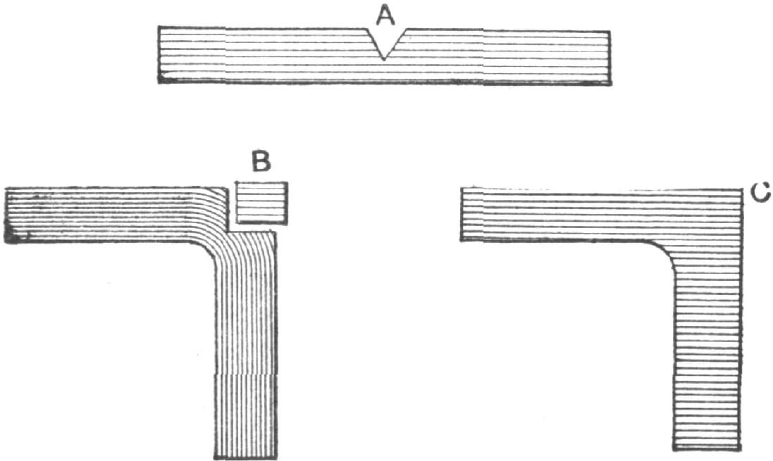
Figs. 176, 177, and 178—“Southern Blacksmith’s” Method of Making a Square Corner
The Breaking of Step-Legs.
Builders of heavy wagons with the step-leg at the back end of the wagon experience much trouble from their breaking. They try to overcome this by making them of thicker and wider iron every year, but they invariably break in the outer hole, and frequently break off the bolts.
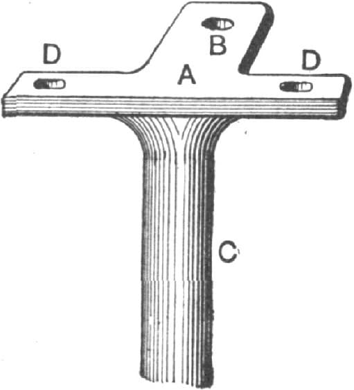
Fig. 179—Showing “Iron Doctor’s” Method of Preventing the Breaking of Step-Legs
In making iron of such a character, at all times avoid, if possible, having holes where the direct strain comes. Fig. 179 shows the proper way to do such work. A is the upper part of the leg and fastened on the underside of the tail-bar, B is a projection, which is secured to the central sills. C is the shank of the leg. D, D, D are the bolt holes. An iron step made and secured in this manner with one or two central braces will last until the wagon is worn out, and will then answer for another wagon.—By IRON DOCTOR.
Making a Thill Iron.
My way of making a thill iron is to take a straight bar of iron of the proper width and bend it square around, forming the stem of the T, as shown by Fig. 180. I then take another piece of iron of the same size as the first, cut the end to be welded a little slanting and weld it on at the bend of the first piece with the long corner out, as shown in the illustration. This leaves the iron straight on the outside, and when made in this way thill irons never break, as they often do when made in the ordinary way.—By JOHN ZECK.
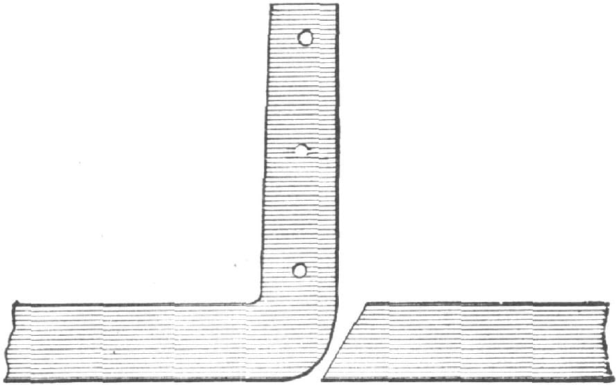
Fig. 180—Making a Trill Iron by the Method of John Zeck
Making a T-shaped Iron.
To make a T-shaped iron, I always take the best of iron, Norway or Swedish, for material.
In making a T-shaped, or in other words head-block plates for a one-seated rig, I take a piece of Norway iron 3 × 3 × 3/4 inches thick, heat the whole piece at once, put it on the anvil, and cut with a hot chisel as in Fig. 181, so that the prong will be 1 × 3/4 inch. I next cut away a little of the corner, as shown by dotted lines in Fig. 182. This prevents a seam, and doubtless a bad job. With two heats I bend with the fuller as in Fig. 183, and then draw out according to the shape of the head block, which must govern the thickness and width of the iron. Fig. 184 represents the piece after the fullering.

Making a T-shaped Iron. Fig. 181—Showing how the Piece is Cut
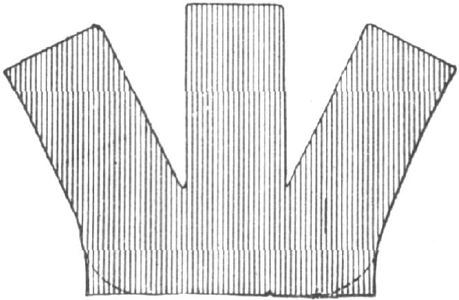
Fig. 182—Showing how the Corners are Cut

Fig. 183—Showing how the Fuller is Used
For larger T’s a larger piece of iron is needed. Be sure you have enough iron, as it will be far better to cut off than to weld on. Leave the corner rounded, as it adds strength. Fig. 185 shows the T finished. After one or two trials you can make one in from three to five heats.—By L. A. B.
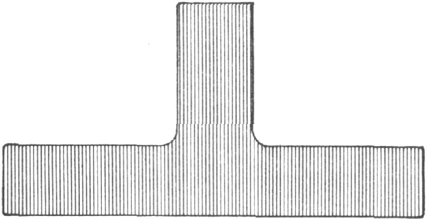
Fig. 184—Showing the Piece after being Fullered

Fig. 185—The Finished T
Making a Step-Leg.
Take iron of the size that will fit in the square hole of the anvil, and split it as at A in Fig. 186, then bend it over nearly at right angles with the standing part, take a welding heat and beat down as in Fig. 187, BB being the upper part and C the leg. Then prepare the pieces F, Fig. 188, heat both to the welding point, insert the part E in the hole and weld F to D.
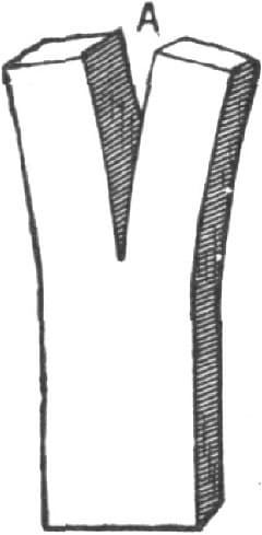
Making a Step-Leg. Fig. 186—Showing how the Iron is Split
If the square hole in the anvil is not countersunk, make tools as in Figs. 189 and 190. H, Fig. 189, is a hole, L and B, Fig. 190 are recesses, and M is a hole. The recesses may be rounded or flat on the bottom, and round at sides as in Fig. 191, or flat on the bottom and beveled on the sides as in Fig. 192. Beveling or rounding are necessary to ensure the ready removal of the iron from the tool. The holes ought to be slightly countersunk to prevent galling.—By IRON DOCTOR.

Fig. 187—The Iron as Bent and Beaten Down
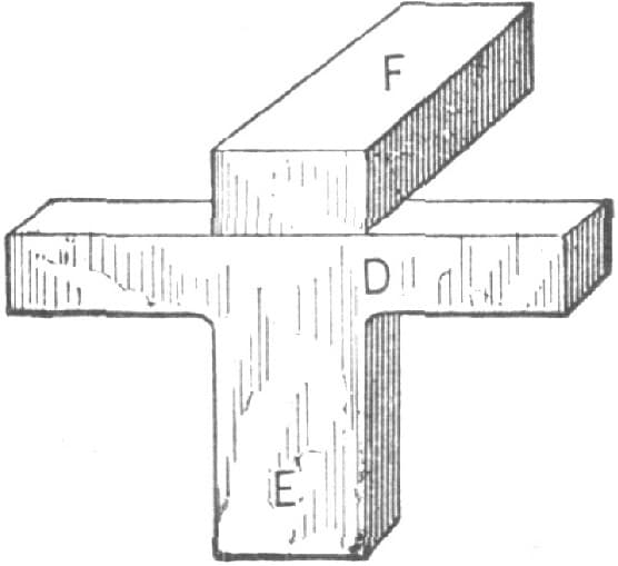
Fig. 188—Showing how the Pieces F and D are Welded Together

Fig. 189—Showing a Tool used when the Square Hole in the Anvil is not Countersunk

Fig. 190—Another Illustration of the Tools used in Making a Step-Leg

Fig. 191—Showing one Method of Shaping the Recess in the Tool

Fig. 192—Another Way of Shaping the Recess
Forging a Head-Block Plate for a Double Perch.
My method of forging a head-block plate for a double perch may be of interest to the trade. It is as follows:
Take good Norway iron 21/2 × 3/8 inches, and forge as shown in Fig. 193, on the back of the anvil; then cut out as indicated by the dotted lines, Fig. 193, then split the ends and turn down for perch ends, finish in the corners with files, draw out the ends of the plate, and you have a forging for a double saddle clip as shown in Fig. 194.
To make a Brewster saddle clip take iron the same size as for the double saddle clip, and use the fuller as indicated in Fig. 195, then cut out according to the dotted lines, split the ends as in Fig. 193, and finish. Then you have a forging as shown in Fig. 196.

Forging a Head-Block Plate for a Double Perch. Fig. 193—Showing how the Iron is Forged and Cut Out

Fig. 194—Showing how the Forging is done for a Double Saddle Clip

Fig. 195—Showing how the Fuller is used in making a Brewster Saddle Clip

Fig. 196—Showing the Forging Completed
I don’t claim that this method is cheaper or better than buying the machine-made articles, but if you want one immediately and cannot get it without waiting two or three days, the next best thing to do is to make it as I have described. —By P. R.
Forging a Dash Foot.
My way of forging a dash foot is as follows: I take a piece of Norway iron 11/2 × 1/2 inch and five or six inches long, fuller it at A as shown in Fig. 197, then forge out as indicated by the dotted line, punch a small hole at B, and then split out as shown by the dotted line. The piece is then ready to be opened out as in Fig. 198. The corners and ends are then squared by swaging and the rough places are finished with a file. The result is a dash foot as neat and substantial as anyone could desire. The welding on is done at C and D. —By J. C. H.

Forging a Dash Foot by “J. C. H.” Fig. 197—Showing how the Iron is Fullered, Punched and Split

Fig. 198—The Piece Opened Out
How to Make a Slot Circle.
I will tell beginners how I make fifth wheels at the factory, I mean those with a slot in them—that is, how I make the slot part.
First make two pieces like that shown in Fig. 199, the parts A A being the same thickness as B, but twice as wide. The distance between A A is made to suit the turning part of the job. Next weld the two pieces together at A A and form the slot C, as shown in Fig. 200, D D representing the B in Fig. 199, and E the ends welded together. Then weld the slot of the clip and get the right lengths. Then fit a piece of iron of the shape shown in Fig. 201 into the slot so as to fill it up, then heat the whole to a red heat and bend around a former. Then the inside piece will contract. The filling is removed when the circle is complete.—By IRON DOCTOR.

Making a Slot Circle by the Method of “Iron Doctor.” Fig. 199—Showing the Shape of the Piece

Fig. 200—Showing the Two Pieces Welded Together

Fig. 201—Piece Used in the Slot
Forging a Clip Fifth Wheel.
My way of forging a clip fifth wheel is as follows: Take a piece of Norway iron and fuller in a recess, as in Fig. 202, then punch in the two holes h, and split to the dotted lines, opening the piece out as in Fig. 203. Next forge the whole to shape, draw out the shanks, cut the threads at their ends and then bend to shape, as in Fig. 204, the face A in Fig. 204 being the same face as A in Fig. 203. Weld at B (Fig. 204) the remainder to form the circle, or if the iron is long enough, and it is prepared, it can be made out of one piece.—By J. C. H.

Forging a Clip Fifth Wheel by the Method of “J. C. H.” Fig. 202—Showing the Piece Fullered and Punched

Fig. 203—Showing the Piece Opened Out

Fig. 204—Showing the Piece Bent to Shape
Method of Making Fronts for Fifth Wheels.
With reference to the subject of fifth wheel making on a small scale, permit me to offer a wrinkle for the consideration of the craft.
The “bow” or “front” of many wheels used to be of a pattern represented by B in Fig. 205. It was made of 1/4 or 5/16 iron. The usual way to form the mitres (which to look well require to be definite) was to upset the iron into a square angle at each mitre point, as at A, then open out and curve the ends to the desired form, and finish the mitres by considerable filing. To facilitate this tedious plan (and it was tedious when thousands were required), I made the tools shown in Figs. 206, 207 and 208. A number of lengths—say 100 lbs.—of the rod, were cut about 5/8 inch for 5/16 inch and 1/2 inch for 1/4 inch longer than the distance (measured with a piece of cord of the same diameter as the iron) between points B and B, Fig. 206, and these lengths were bent cold into the approximate shape or form shown by the dotted line B, Fig. 206. The swage and top tool being ready, a number of cold shaped blanks were put in the furnace or forge, and the helper taking out one at a time when white hot along the crown or middle, dropped it into the swage, when by two or three smart quick blows with the sledge upon the top tool C, Fig. 206, the bow or stay would be complete and ready for welding into the split ends of the circle top. The job I have described is completed without the use of a file. Done by the old plan, filing had been quite an item of expense and it is hardly necessary to say that I never went back to the old method.—By W. D.

Making Fronts for Fifth Wheels. Fig. 205—Showing the Old Method of Making the Mitre
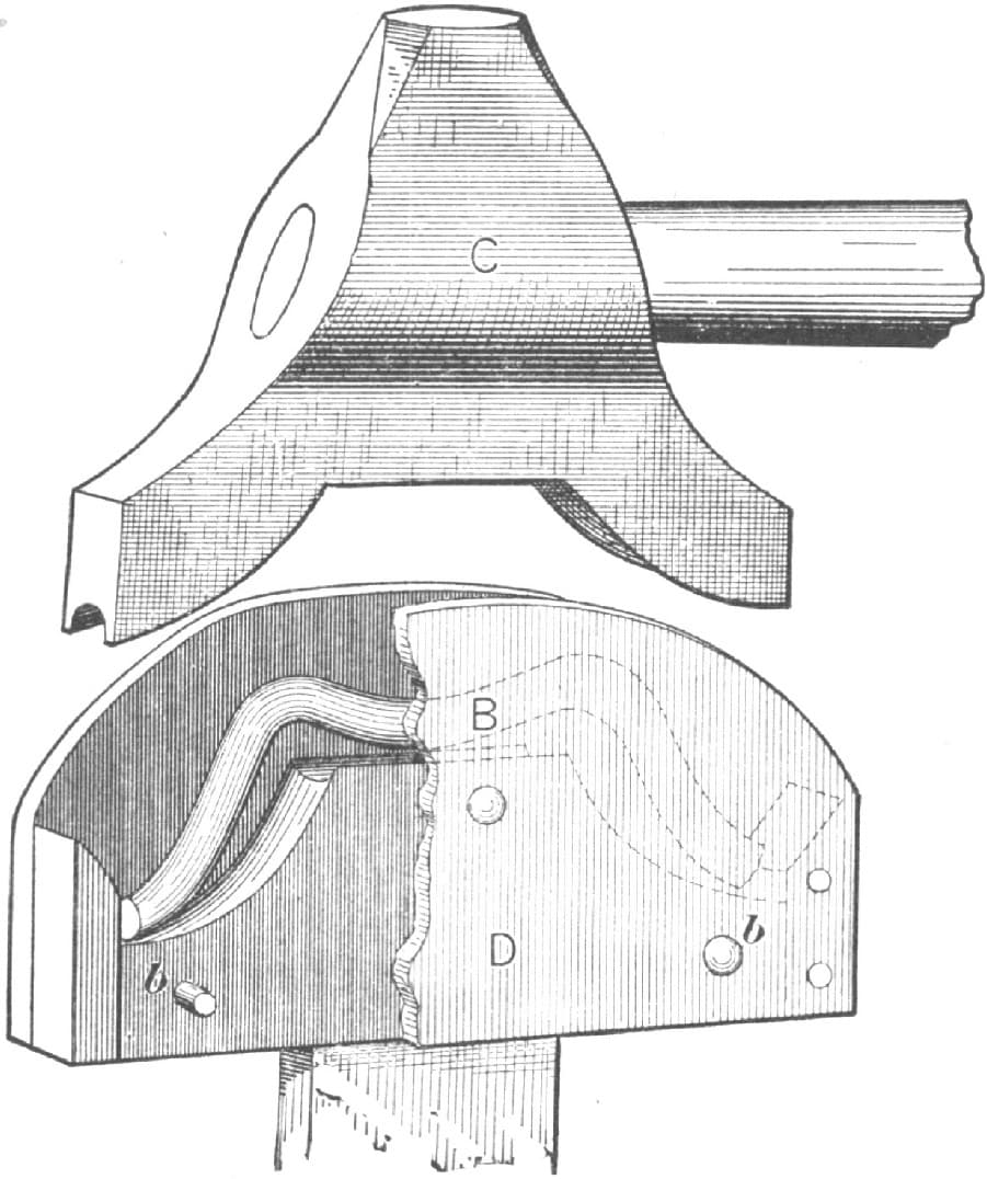
Fig. 206—Showing the Top Tool and Swage Used
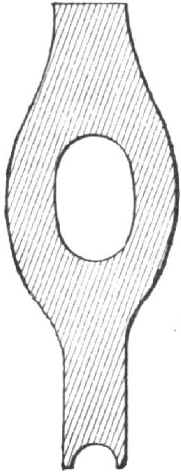
Fig. 207—End View of the Top Tool

Fig. 208—End View of the Swage
Making a Fifth-Wheel Hook or a Pole Stop.
To do any work properly and quickly we require the right kind of tools. In making a fifth-wheel hook on a pole stop we need a heading tool, as shown in Fig. 209. A is the thick heading portion. B is the thin heading post. C is the square hole. D is a section of the hard portion. Take good iron of the proper size, draw down and form the end D, shown in Fig. 210, to fit the square hole C in the tool. Heat the iron, insert in the tool, and split with the splitting chisel, as at E. Next, with a small fuller open up the split, as at K, Fig. 211, sufficiently to insert a larger fuller without continuing the split further down. The part F is inserted in the tool, and H is thrown off. Next take a larger fuller and force down H, as at N in Fig. 212, L fitting in the tool while M is still upright. Twist N to the shape desired, then repeat and insert the part O, Fig. 213, in the tool, hold the sledge on S, turn down P and dress up the whole with the set-hammer. R is the space or recess covering the fifth wheel when the device is used as a fifth-wheel hook, and resting on the cross-plate when it is used as a pole stop. Remove the piece from the tool and round up the end O to the proper size for the thread and nut. The square portion is for a fifth-wheel hook, and should be left just as long as the iron is thick through which it passes, less enough to give a set or tension with the nut. The thread should be cut clear up to the square portion. The nut ought to be over the standard thickness to admit of having an extra thread, with a view to getting a better grip.

Making a Fifth-Wheel Hook or a Pole Stop. Fig. 209—The Tool Used

Figs. 210 and 211—Showing how the Piece is Split and Fullered

Fig. 212—Showing the Next Stage in the Fullering Process
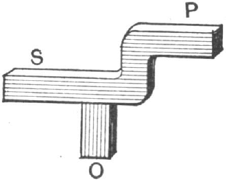
Fig. 213—Showing the Job Completed
For a pole stop make the shank the same as you would a bolt. The beginner may require four or five heats to make one. A little practice will reduce the labor to three heats. We have seen experts do them in two heats.—By IRON DOCTOR.
Making a Shift Rail.
The accompanying sketches represent a new and inexpensive method of making a shift rail for buggy seats, as the following explanation will show: Take a piece of 5/8 by 7/16 inch oval Norway iron, upset it at A, in Fig. 216, then take an oval-pointed cold chisel and make a hole in the place where it was upset large enough to admit a piece of 3/8-inch round iron, with a collar swaged on one end of it as shown in Fig. 216. Take a good welding heat at the point where the two irons intersect, and then place in the swage shown in Fig. 215. Place the swage shown in Fig. 214 on top and strike a few blows with a sledge hammer. The result will be a forging of the kind shown in Fig. 217, ready for welding on the goose neck and arm rests, as shown by the dotted lines. In strength this construction is about equal to a forging made out of solid iron, while it is exactly the same in looks. The swages shown in Figs. 214 and 215 are made the same as other swages employed by blacksmiths, except that those shown in Fig. 215 should be provided with a piece of band-iron arranged as indicated by the dotted lines. This should be shrunk around it. It projects above the face of the swage a distance of three-quarters of an inch or more, and serves the purpose of holding the top swage in correct position while taking the weld.—By C. T. S.

Making a Shift Rail. Fig. 214—Upper Part of the Swage
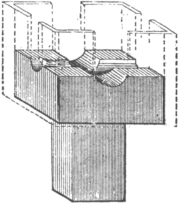
Fig. 215—Lower Part of the Swage used in Shaping the Rail

Fig. 216—The Shift Rail Commented

Fig. 217—The Finished Forging Ready for Welding
Making Shifting Rail Prop Irons by Hand.
The following description of some tools for making shifting rail prop irons by hand, with sketches showing how to make an iron in the tools and how to prepare it for the tools, describes my method of making shifting rail prop irons. Fig. 218 shows the prop iron as it is when finished. To make this take the proper size of iron and split it out as in the dotted lines of Fig. 222, which will give two irons as in Fig. 223. With the same heat used in splitting out the two pieces draw the square A, shown in Fig. 223, so it will fit the square B of the tool shown in Fig. 221; now split Fig. 223 as at X, and with the same heat place the square part A in the square part of the tool, Fig. 221, at B; then turn down the part O, then, with an ordinary top swage, swage it down; now take the iron out of the tool and reheat it, edge it up and place it in the tool Fig. 219, and use the top swage, Fig. 220. The tool, Fig. 227, gives the iron a complete finish and makes all irons alike at the corners, which is a big gain where irons are to be duplicated. The tool, Fig. 219, is used on the anvil the same as any ordinary heading tool. Hold the corner on the anvil while swaging the corners; while swaging over the square part set the square part of the prop iron in the square hole of the anvil, and so on. In a short time any ordinary smith will be able to handle the tools properly and make a good iron. I do not think it necessary to give any further description of the tools, as I think the sketches will speak for themselves.—By H. R. H.

Fig. 218—Showing the Finished Prop Iron
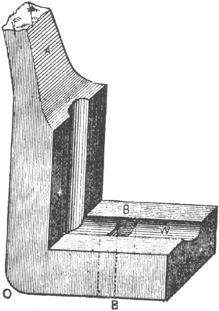
Making Shifting Rail Prop Irons. Fig. 219—Showing the Tool used to give the Iron a Complete Finish
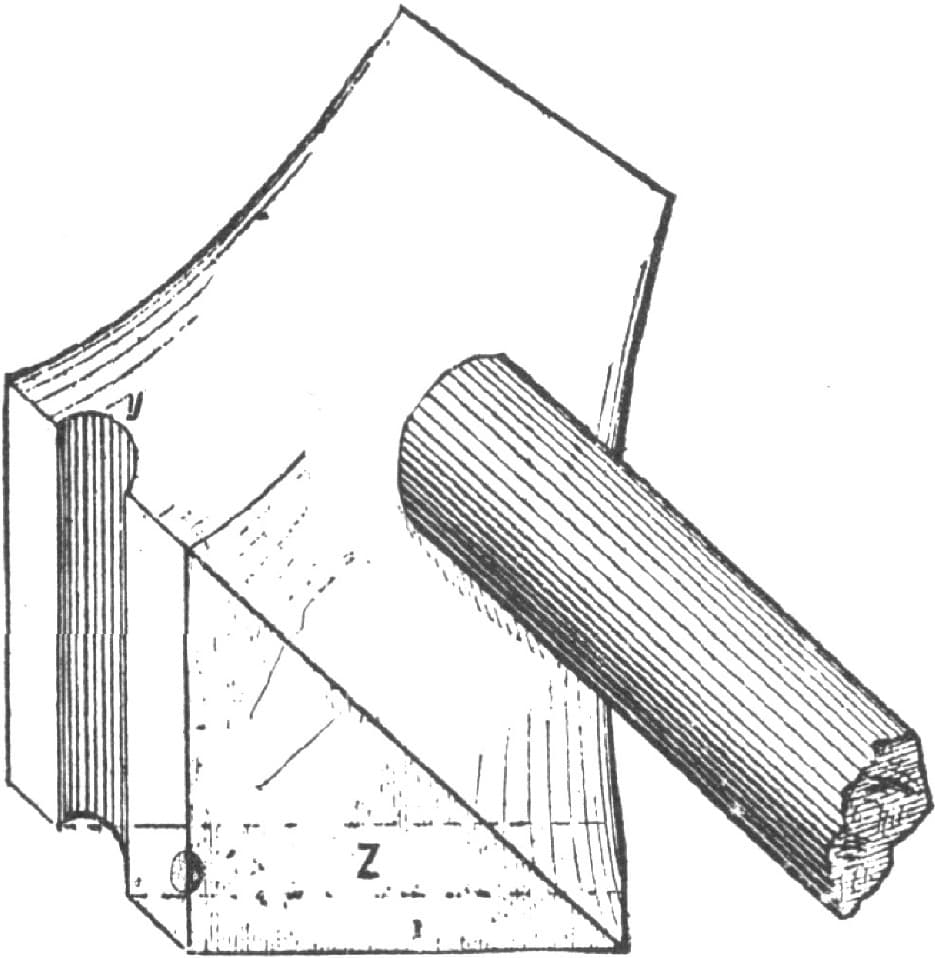
Fig. 220—Showing the Top Swage

Fig. 221—Showing the Tool to which the Square A is Fitted
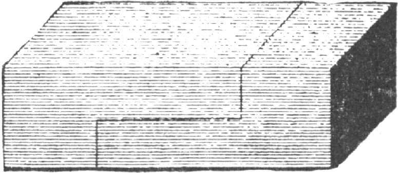
Fig. 222—Showing the Lines on which the Iron is Split
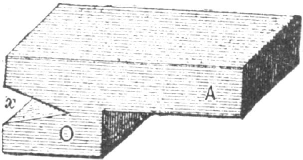
Fig. 223—Showing the Iron Split
Getting out a Solid King-Bolt Socket.
My way of making a solid king-bolt socket is as follows:
I first make a block as shown in Fig. 226. It is about four and one-half inches long, and if the plate is to be one and one-quarter inches wide, make the block, A, two and one-half inches wide and one three-quarter inches thick; make the swage part, B, one and one-quarter inches half round; make the hole nearly one and five-sixteenths inches in diameter at the top and taper to one and one-quarter inches on the bottom, which permits of the easy removal of the iron. Then take round iron one and one-quarter inches in diameter and five inches or more long, as shown in Fig. 224, split, as shown in Fig. 225, three inches down, and open up; split with a dull chisel or round fuller, swage the joint of round portion just a trifle so as to allow it to enter the block easily, reheat to a moderate heat and then insert the tool in the block. If the square hole in the anvil is not large enough, or a swage-block is not at hand, hold the piece over the open forging vise and bend the ends down moderately until nearly a right angle is formed. Next cut off the end so that it will be less in length than the block is thick by a matter of three-eighths of an inch, raise a welding heat, insert the point in the block and flatten or set down into the swage—first with hammer and sledge, striking quick blows so as to weld up any looseness, then use the flat hammer to finish—as a result we get Fig. 227—in which A is the plate and B the stem or portion to be converted into a socket. Then weld in iron of the proper size, draw and swage to a finish and fit while the iron is cooling off.

Getting Out a Solid King-Bolt Socket by the Method of “Iron Doctor.” Fig. 224—Showing the Iron before Splitting

Fig. 225—The Iron after Splitting

Fig. 226—The Block
I will say just here that it is very improper to fit iron to wood by burning it on as some stupid blacksmiths do. Hit the iron while it is black hot, and should it still burn, rub chalk over the portion which comes in contact with the iron.

Fig. 227—The Plate and Stem
The socket is finished inside with two drills, one for the insertion of the smaller portion of the socket, the other to make a passage for the king-bolt, which in this case may be five-eighths of an inch. In Fig. 227, A denotes the plates; B the full-sized part of the socket and the same diameter as the socket; C, of Fig. 228, is the small portion of the socket which fits in the socket and is formed by swaging. Fig. 229 represents a good tool for turning off the upper portion of the socket; A is the portion which fits in the drill-chuck; B the waist, about three-quarters of an inch diameter; two inches long; C, the body of the tool, one and one-quarter inches diameter, two inches long; hole F may be one inch by one and one-half inches for the insertion of the portion marked A, about three and one-half inches long, one inch by one and one-half inches. B is the cutting part. In Fig. 229 is shown a set-screw to hold the cutter fast. The point E fits the hole in the socket and acts as a guide. With a little practice the tools shown in Fig. 228 will answer as well as a lathe. —By IRON DOCTOR.
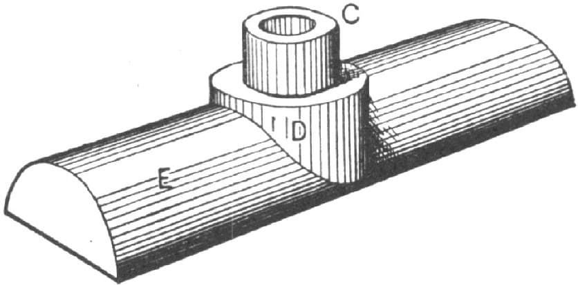
Fig. 228—The Plate and Socket

Fig. 229—Showing a Tool for Turning Off the Upper Portion of the Socket
Heading Bolts.
I send a sketch in Fig. 230 showing a heading block for an anvil, the mouth of the hole being worn rounded, as shown at b b, which would let the iron fill in, as at c c in Fig. 231. Now a very little wear there will let the iron fill in enough to make quite a difference in the length of blank required to make a bolt-head to any given dimension. But the extra iron is not of so much consequence as the swell in the bolt neck, which is a great nuisance, especially where both are to be threaded clear up to the head. In the anvil block used in our shop we have steel dies set in the block, as in Fig. 232 at d. By this means different sizes or dies may be fitted to one block. The dies may be turned upside down, by making the dies d longer than the recess is deep, so as to stand above the top of the block. We are enabled to heat the dies and close up the holes when they have become too much worn.—By J. R.

Fig. 230—Showing the Heading Block for the Anvil

Fig. 231—Showing the Iron filled in at C C

Fig. 232—Showing the Steel Die Set in the Anvil Block
Heading Bolt Blanks.
In heading hexagon bolts I allow three times the diameter of the iron, providing the heading tool is the proper size. Suppose, for example, a 3/4-inch bolt is to have a stem three inches long. Then in cutting the iron rod into blanks I make the blanks five and one-fourth inches long, which allows two and one-fourth inches of blank length to form the head, the bore of the heading tool being 3/4 and 1/64. The header, or the dies, as the case may be, should by rights be of steel, as cast-iron wears very quick; and after five hundred bolts have been made in a cast-iron die there will be so much wear that the heads will not come up to size with the above allowance.
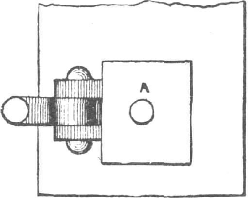
A Substitute for a Bolt-header, as designed by “J. R.” Fig. 233—Top View
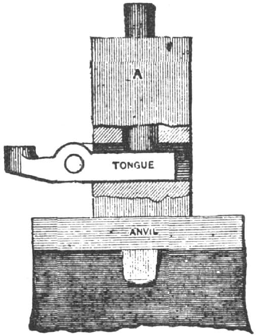
Fig. 234—End View
A good shop tool for short bolts, which I like better than a bolt-header, consists of a block A, Fig. 233, with stem to fit in the square hole in the anvil, and having a slot through it to receive the usual tongue. Fig. 233 is a top view of the tool, and Fig. 234 is an end view.—By J. R.

Bending a Cast-Steel Crank. Fig. 235—Showing the method of Bending at A A
Bending a Cast-Steel Crank Shaft for a Ten Horse-Power Engine.
The illustrations herewith will show how I made a crank, the shaft for which was two and one-half inches in diameter. I made the bends at A and A first, and shaped as shown in Fig. 235. I then heated at B, cooled off A, and bent as seen in Fig. 236. I then heated at A, B and B, cooled off A, and bent as shown in Fig. 237. From A to A in Fig. 235 I allowed fourteen inches to make a five-inch stroke. I straightened so as to turn to two and three-eighths inches, and there was not a cockle or a scale on it.—By SOUTHERN BLACKSMITH.
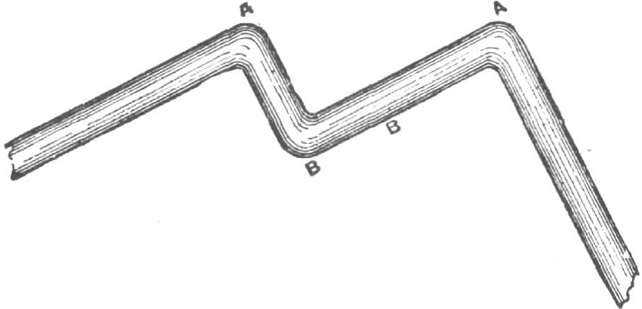
Fig. 236—Showing the Crank Bent at A, A and B

Fig. 237—Showing the Job as Completed
Making a Clevis.
A man can learn his trade with a good mechanic, and then go in another shop and see the same piece of work done in another way, much simpler and easier than his. To illustrate this point, I will explain what I once saw a good workman do. The job I refer to was the making of a clevis. He wished to make a five or six-inch one as follows: Large in the center, tapering forward to the bolt holes, the holes to be flat on the inside and round on the outside. That required the iron to be half round to form the collar for the bolts. To do this he cut the iron to the length required, drew out the ends, bent it over the horn of the anvil, then over a mandrel, took a heat, welded down, and then hammered it over the horn again. By this time it required another heat, as it needed more drawing, and this way of doing the job took twice the time really necessary for it. He then finished the other end in the same way, bent it, and this completed the work, the collar being then as shown in Fig. 238 of the accompanying illustrations.

Making a Clevis by the Method of “T. G. W.” Fig. 238—Showing the Ordinary Way
Now, he could have saved both time, coal and labor by having taken a piece of iron the required size, drawn out the ends, then laid it in a swage and taken his set; then flattened it back two and one-half inches, or one and one-half inches, from the ends, flattening say three inches in the swage. This would have made it as shown in Fig. 239; and after beveling and welding the collar the holes would have been as shown in Fig. 240.—By T. G. W.

Fig. 239—Showing the Piece as Drawn Out and Flattened

Fig. 240—Showing the Clevis After Beveling and Welding
Crank Shafts for Portable Engines.
Herewith I send you sketches of my plan for making crank shafts for small portable engines.
Fig. 241 shows the pieces composing the crank, and the other figures the details, having on them the same figures of reference.
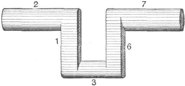
Fig. 241
First make two pieces, as shown at 1 and 6 in Fig. 241, and weld Fig. 242 to piece 1; then weld Fig. 243 to piece 1; next weld around the ends of 1 in Fig. 244 two straps, these straps being shown at 4 and 5. I weld up the other half in like manner. I sometimes make cranks in this way that weigh up to 150 lbs.—By SOUTHERN BLACKSMITH.

Fig. 242

Fig. 243

Fig. 244
Forging a Locomotive Valve Yoke.
PLAN 1.
My method of making a valve yoke and stem for locomotive engines requiring but one weld (these parts are usually made with three welds; the saving accordingly will at once be perceived) is as follows: I take a car axle, or any iron of the required size, heat and weld it properly, set it down with a fuller to form the corners, allow for draw between each corner, and then draw to the required size as shown in Fig. 245. I leave plenty of stock in the corners so it can be trimmed with a chisel as necessary. I next bend as shown in Fig. 246. To make the stem I use two-inch square iron, which I twist and weld up the entire length to change the grain of the iron, so that it will not cut the packing or stem. I leave the end for welding on to the yoke as shown in Fig. 246. I take separate soft heats on each, being sure to have them clean, and then weld.

Locomotive Valve Yoke. Fig. 245—The Piece Before Bending
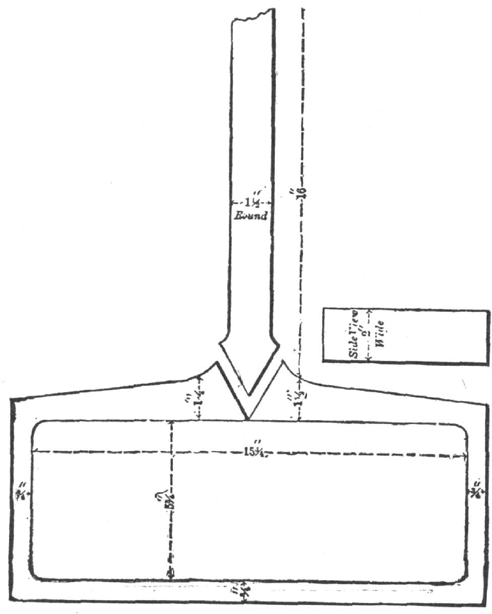
Locomotive Valve Yoke. Fig. 246—Formed, Ready for the Final Weld
Although I use no clamps, I have never had any trouble from the valve yokes springing. I allow that side to come a little long, as it is easier to stave work of this kind than it is to draw it. My reason for considering a V weld the best is that we have more surface to weld in a V weld than we could get in a jump weld; besides, we get into the body of the work that is to be done. Any blacksmith who will subject the two welds to a fair test will soon be convinced that a jump weld will show flaws and break under less pressure than a V weld. Why do most smiths V steel in bars, sledges and other similar work if lap or jump welds are best?
The usual way of making articles of this kind is to have a weld in each forward corner or in each side, having a jumped weld for the stem. By the plan that I pursue a V weld is used, which is the best that can be made. The oil and steam will soon destroy a jumped weld, as they are frequently unsound. The sketch is reduced from full size. The figures, however, denote the dimensions of the finished work.—By R. O. S.
Forging a Locomotive Valve Yoke.
PLAN 2.
I think that the plan I show in the sketch herewith is a good way to forge a locomotive valve yoke, and it has the advantage of having only one weld. The yoke is forged around as in Fig. 247, and scarfed up for the rod weld, which is formed as in Fig. 248, the weld being made as in Fig. 249.—UNKNOWN.
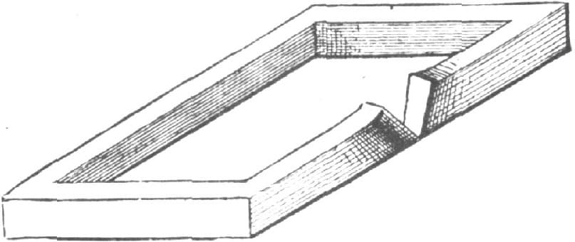
Forging a Locomotive Valve Yoke, “Unknown’s” Method. Fig. 247—Yoke Bent and Scarfed Ready for Weld

Forging a Locomotive Valve Yoke. Fig. 248—Rod Scarfed for Weld

Forging a Locomotive Valve Yoke. Fig. 249—Rod in Position for Welding
Forging a Locomotive Valve Yoke.
PLAN 3.
The following plan of making a locomotive valve yoke is followed in my shop: We cut an axle to the length desired and draw the stem first, leaving it square as shown in Fig. 250. We then draw the other end, and punch and cut under the hammer until we get the shape shown in Fig. 251. We next split, straighten and open out as seen in Fig. 252. The ends are then drawn out on a table such as is shown in Fig. 253. The stem is then twisted by placing the opened ends under the hammer, and applying to the square end the lever shown in Fig. 254. A piece of iron like that shown at A in Fig. 255 is then forged down, the two valves of the yoke are put together, and we weld as shown in Fig. 255, bolting the two pieces together by the clamp C. Or we forge the second piece longer on its ends and weld as in Fig. 256.

Making a Valve Yoke by the Method of “Novis Homo.” Fig. 250—Side and End Views of the Stem after Drawing

Fig. 251—Side and End Views of the other End after Drawing, Punching and Cutting

Fig. 252—Showing the Piece Opened

Fig. 253—Showing the Piece Straightened in the Table

Fig. 254—Showing the Lever Used to Twist the Rod End
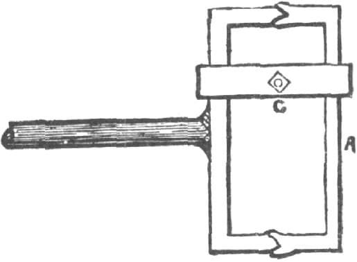
Fig. 255—Showing the Piece C Drawn for Welding

Fig. 256—Showing Another Method of Welding
We have also a face plate designed especially for making valve yokes. It is like the one shown in Fig. 253, excepting that it has but one hole. In speaking of hammers I mean steam hammers.—By NOVIS HOMO.
Forging a Locomotive Valve Yoke.
PLAN 4.
Locomotive blacksmithing is one of the most important branches of the trade, and requires all the skill and experience that the smith can command. I do not know that I can show a better way than the preceding, but I will attempt to describe my way, which I think a good one. In the first place, after having got the required size iron, I jump the stem and draw both ends (all as shown in Fig. 257). The next operation is simply to bend into shape and weld as shown in Fig. 258. —By VULCAN.

Locomotive Valve Yoke. Fig. 257—Showing Yoke Jumped and Drawn for Bending

Fig. 258—Showing Yoke Bent and Welded
Forging a Locomotive Valve Yoke.
PLAN 5.
Many yokes lack durability because the oil and tallow used in oiling the valves contain some substance which eats into the fiber of iron if it can get at the end of the bar. I have seen many yokes made in “Unknown’s” manner that were eaten in from one-half to one and one-half inches at the end of the stem. If in welding steel on the stem close to the yoke—that is, the stuffing box—you do not get a perfect weld, or if a flaw is left at the point of the steel or the scarfs of the iron, the corrosive substance to which I have alluded will soon eat a hole in the stem, and perhaps all through it.—By R. T. K.
Forging a Locomotive Valve Yoke.
PLAN 6.
While I am, as a rule, in favor of the V weld, I do not like its application to the valve yoke, as I believe it is liable to spring from being so weak in the ends and the opposite side. I prefer a yoke made on “Unknown’s” plan, because that obviates the danger of “springing” while the stem is being welded. My own method is first to bring to the shape represented in Fig. 259 of the accompanying engravings. The yoke I make has the two ends and side of the same size. I then bend as shown in Fig. 260. By this plan I save the time needed to make a corner.—By R. D.

Making a Locomotive Valve Yoke by the Method of “R. D.” Fig. 259—Showing the Piece Ready for Bending

Fig. 260—The Yoke Bent
Forging a Locomotive Valve Yoke.
PLAN 7.
Before giving my method of forging valve yokes I shall criticise briefly “R. O. S.’s” method of making them. He finishes the yoke where I should begin it. He says: “I first get out my iron in the shape shown in Fig. 261 (see the accompanying illustrations). I then bend as in Fig. 262.” It will be seen that “R. O. S.,” in his method, has four corners to form of the right shape and length before welding on the shank A; consequently, if he is unlucky—and this may happen to the best of workmen—his labor is all lost, and the iron goes to the scrap pile. No one can weld A to B without stretching the yoke, and when this occurs the yoke assumes the shape shown in Fig. 263, thereby making it necessary to go all over the work again. Still, if a former the size of the inside C is at hand (and it ought to be), the yoke can soon be got into shape again.

Forging a Valve Yoke by the Method of “R. O. S.” Fig. 261—Shape of Iron at Start
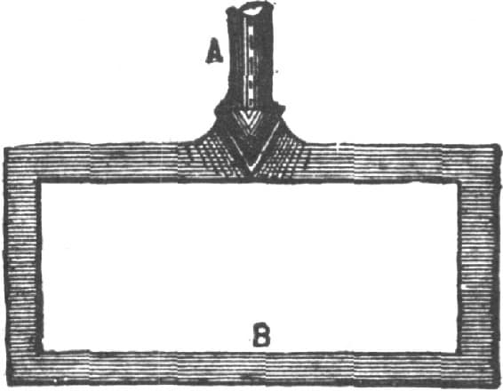
Fig. 262—The Piece Bent to the Yoke Form

Fig. 263—Showing the Result of the First Error in the Method of “R. O. S.”
Then “R. O. S.” twists the stem A to change the grain of the iron, so that the packing on the stem will not be cut out. In twisting and welding up for the stem as he suggests, you twist with the iron whatever is in it, and in so doing you make a spiral of the stem as shown in Fig. 264, and if there is any hard substance left in the iron it is scraped out through the packing by the motion of the rod, somewhat in the manner in which a rat-tail file would operate in drawing it back and forth in a hole. If you do not twist your rod, although it has sand in it, you get your cut in one or two places, according to the purity of the iron. Twisting does not remove impurities, neither does welding, so the time consumed in such work is lost, for bar iron as clear as steel can be got for what this twisting and welding would cost.

Fig. 264—Showing the Stem Twisted
Perhaps some of the plans of my own, which I shall now give, may not seem feasible to all of the craft, but I have found every one of them satisfactory. I have six plans. The first is as follows: I take a piece of good iron, draw it out into shape as shown in Fig. 265, then form as shown in Fig. 266, and weld at C, by splitting as in Fig. 267.

Fig. 265—The Iron Drawn into Shape

Fig. 266—The Second Stage in the Job
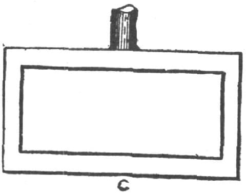
Fig. 267—The Yoke Completed
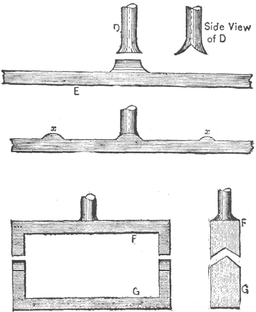
Forging a Valve Yoke, by “J. T. B.” Fig. 268—The Second Method
Fig. 268 shows my second way of forging a valve yoke. I jump D to E, by splitting D, then forge, leaving projections at X to bring up the corners, shape the bend around, as at P G, split F, forge a piece G and weld P and G together.
In my third method, shown in Fig. 269, I round the end of the stem, and open the ends of the part J, then forge a separate piece K, and weld J and K together.
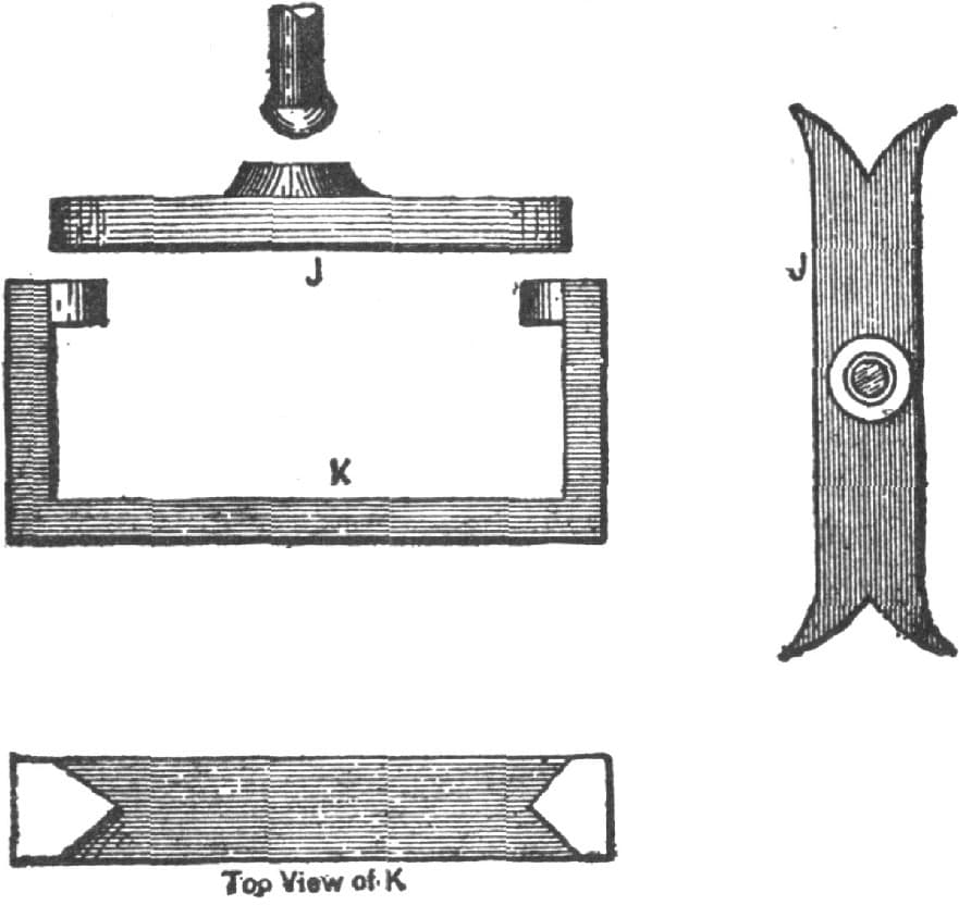
Fig. 269—The Third Method
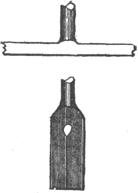
Fig. 270—The Fourth Method
In my fourth method, illustrated in Fig. 270, I take a piece of Norway iron, of sufficient size, draw out the shank or stem, then punch a hole, as in Fig. 270, and open out the two ends, thus getting the stem out of the solid.
In the fifth method, as shown in Fig. 271, I take iron of suitable size, say 11/2 × 3/4 inches, make the L-shaped piece shown in the engraving, put all together, and weld them up, and complete the forging in any of the ways already mentioned.
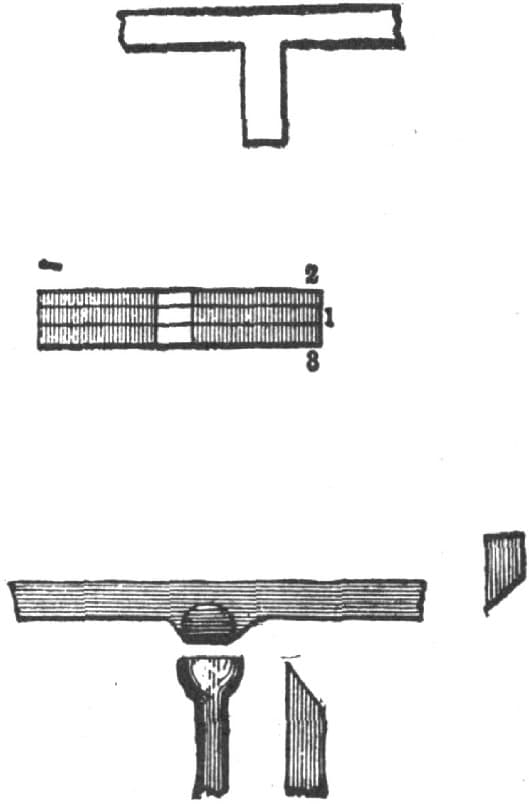
Fig. 271—The Fifth Method
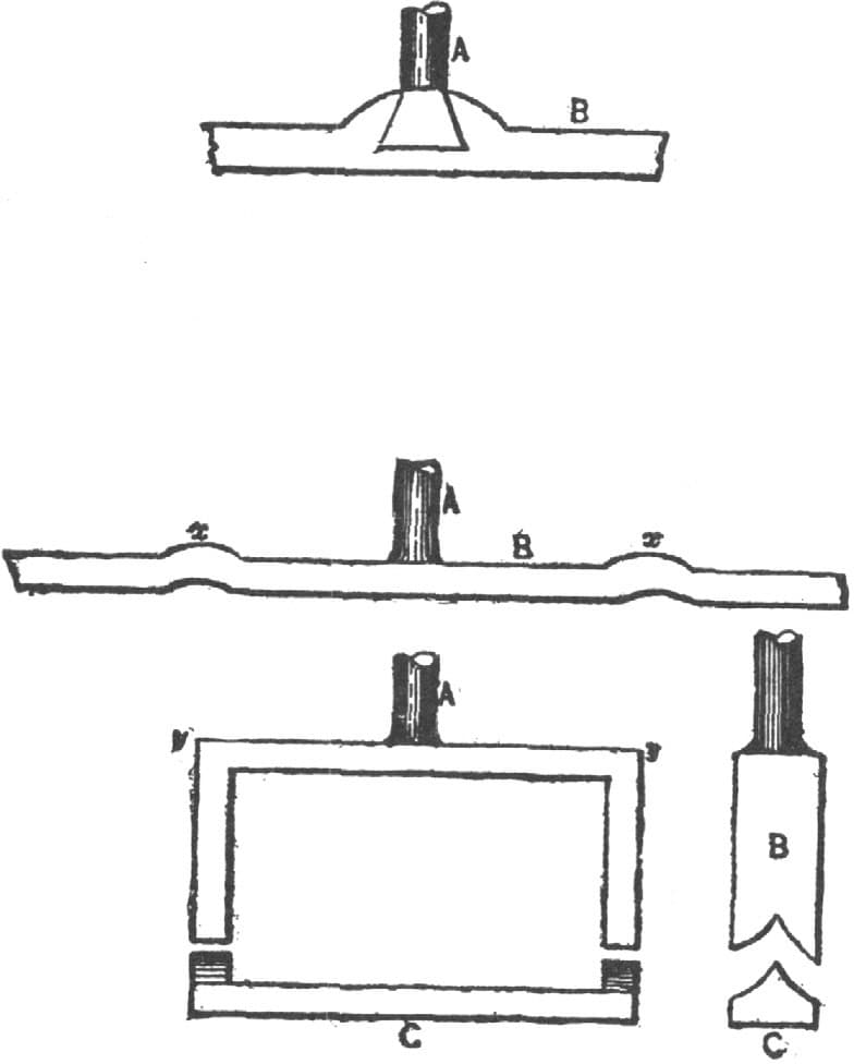
Fig. 272—The Sixth Method
My sixth method, as illustrated in Fig. 272, is to get out a piece B (Fig. 272) and use the dovetail weld shown to weld in stem A, the stem being drawn in sideways; the corners at x are where the corners y will come. I split the ends of B, and weld in a piece C.
Now all these plans are good and practicable. They show six good methods of putting a shank on a flat bar of iron, and all in keeping with the general custom among skilled workmen.—By J. T. B.
Defect in Engine Valve.
The defect in many valves is owing to the fact that the cylinder exhaust port is not made wide enough for the stroke of the valve. If the valve is worked by a rock-shaft, and there is any room to lower the pin in the rocker arm that carries the eccentric hook, the stroke of the valve can be shortened and a better proportion between the steam and exhaust ports obtained thereby. Shortening the stroke of the valve will prevent the edge of the exhaust cavity in the valve from working up close to the edge of the cylinder exhaust port, Fig. 273, and will prevent the exhaust steam from being cramped. Fig. 273 also shows part of the exhaust lap chipped from the valve, which I shall speak of presently. If the valve stroke is shortened it must have the stroke so that it will open about three-quarters of the steam port. It may be well to state that by lowering the eccentric hook pin it will be necessary to lengthen the eccentric rod, or it will throw the valve too much to the front of the cylinder, and make the port openings unequal.

Fig. 273
As the valve has an excess of exhaust lap it would be well to take a straightedge and scriber and mark off one-third of the exhaust lap, as shown by the dotted lines in Fig. 274.

Fig. 274
Then take a sharp cold chisel and chip off the marked edge, inclining inward to the valve at an angle of 45°, as shown in Fig. 274. By this method there will be a free and easy exhaust, and great compression prevented, even though the engine runs at a very high speed. If the valve stroke cannot be shortened, then chip out nearly one-half of the exhaust lap.—By SLIDE VALVE.