CHAPTER VII
PLOW WORK
Points in Plow Work.
NO. 1.
My method of putting plowshares on stubble plows is as follows: I commence by preparing the landside, as in Fig. 313, and attaching it on the plow in the proper place. I next cut out the steel, as in Fig. 314, then heat the part from A to B, and drive it over so that when the back of the steel is against the moldboard the line A B will be on a direct line with the landside. I next plate it out to a thin edge from heel to point, and then heat it evenly all over so that it will bend easily to the blows of the hammer. In preparing this part of the lay to fit the landside and moldboard, the smith should be very careful to leave no hammer marks on the front side, and he should also be careful to get a good fit, as that is much easier at this stage than when the part is welded on the landside. When this piece of steel is fitted as I have described, attach it to the plow by fastening it at the heel to the brace, and in front by fastening it to the landside with a clamp made after the pattern shown in Fig. 315. This clamp should be made so that after being put on at the point it will be driven tight when about two-thirds of the way upon the lay, thus holding the steel fast to the landside so that it will weld easily.

Points in Plow Work. Fig. 313—Showing the Landside

Fig. 314—The Steel

Fig. 315—The Clamp
The next thing to be done is to unfasten the lay from the plow. Prepare a good fire and weld quickly, being careful not to let the piece slip or disturb it any more than is necessary. When it is welded to the top, and before finishing the point, lay a piece of steel from the edge of the point back about two or three inches; this will make the part last much longer. Next finish up the edge and point and edge of the lay, and if it has been held in place you will have a perfect fit.
When it is desired to put on a point, in preparing the point I forge one end of the steel flat and draw it to a thin edge, the other I draw to a point, as in Fig. 316, and then double it so the pointed edge will go on the bottom of the landside. I next weld both sides down solid, draw out to required thickness, cut off the edge of the point at the same angle as the lay, finish up and the point is complete.

Fig. 316—The Point
Sometimes a lay is brought to the shop that is worn very thin, and some are worn through at the top, near the moldboard. In this case I forge the point the same as I would in the one just described, but leaving the flat side long enough to reach the top of the lay. I then bore a hole near the top through both the piece of steel and the lay and fasten them with a rivet. I next heat the piece of steel where it is to be doubled over, letting the pointed piece go on the bottom of the landside, weld up as high as is convenient, and finish as before.
For the purpose of cooling a lay easily and with more rapidity, I use a wooden block about eighteen inches in diameter and two feet long. I square one end, place it upon the floor, and saw the other end to the shape of a half circle, as shown in Fig. 317. This cavity is lined with iron so the wood will not burn. When the lay is heated I put it upon the opening and place a piece of round iron about three feet long and two inches in diameter upon the part that is to be shaped, one end of the piece being held in my hand; the helper then strikes upon the round piece with a heavy hammer and the lay will bend evenly without leaving marks.—By T. M. S.
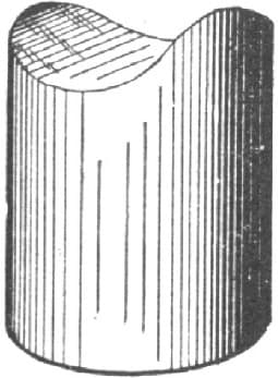
Fig. 317—The Block used in Cooling the Lay
Points in Plow Work.
NO. 2.
I always weld my points on the top instead of the bottom. My reason for this is, that the share always wears thin above the point, and by drawing your point tapering, leaving the back thick, and drawing the edge that extends on the face of the share thin and wide, you make the weak places strong. All smiths know that the throat, especially where it is welded next to the bar, wears thin, and unless you place your point on the top side, it is soon worn through, and the share must be thrown aside. In drawing the shin piece, the piece that is welded from the point of the share to the point of the mold should be drawn to a feather edge where it extends on to the wing and left heavy on the back, so that when it is welded on it will scour off and become smooth. I have seen many shares that would not scour simply from the fact that the edge had been left thick, and in welding the smith made the wing sink in, and left a place for the dirt to stick.—By W. F. S.
Some More Points about Plows.
That bolts are among the most important things when it comes to repairing plows, I shall endeavor to show in the following remarks.
In all the plows made in factories, that is the steel plows, with very few exceptions, the round countersink key head is used, or else a square neck round countersink head, which is very little better than the key head. It seems to me that plow factories lose considerable profit on this item of bolts.
My plan consists in simply punching a square hole, tapering to fit a square plug head bolt. I hear some one ask how would I punch a tapering hole. I will tell you how I do it. The size of bolt I use for a bar is seven-sixteenths and half inch. Make a square punch a trifle larger than the bolt, so it will go in without driving and will not spoil the threads, then make the die, say for a seven-sixteenths inch bolt, three-eighths of an inch, set it so the punch will pass through the center, now try it and see if it does not make a taper hole fitting a plug-head plow bolt. Make any other size punch and die in about the same proportions to get the taper. You can punch every hole in the mould the same way. Sometimes the corners of the hole will not be cleanly cut out, and in that case take a square pointed punch tapered and tempered, set it in the hole and hit it once or twice.
I think I have shown where two expensive operations with the vise and drill can be saved, and in doing this it is necessary to have only one variety of bolts to use. Then when it comes to repairing the same there is no turning of bolts in the hole. If it is so rusted that the nut won’t turn it is better to twist it off and put in a new bolt, at a cost of five or ten cents, than to spend a half hour trying to get the old one out, and then have to charge for the time and bolt beside.—By DOT.
Making a Plow Lay.
I will describe my method of making a plow lay:
If a new stub on landside is to be made forge it out first. Sometimes the old one can be used by welding a piece on the point and letting it run upon the top of the old stub. After the stub is bolted on, lay the slab of steel on the plow and mark the bevel, then lay the block of a two-inch square on the steel, and mark as shown in Fig. 318 of the accompanying illustrations. Next heat and turn the point and draw and cool the lay so that when the plow rests on the floor the edge will touch over the entire length of the lay. Next cut out a small piece of steel to lay on the bottom of the point, and punch a hole through the point of the lay, the landside and the small piece of steel, and rivet them all together. Then take off together the entire landside and lay, weld the point first, then take off the long landside and weld the upper end of the stub to the lay, and weld the middle last. Never try to weld from the point up, for the steel will curl or spring up from the stub and prevent your getting a good weld. While heating the point hold it by means of the clamp shown in Fig. 319. Fig. 320 represents the point used for the bottom of the lay. I use borax for a flux.—By B. N. S.

Making a Plow Lay. Fig. 318—Showing how to Mark the Steel
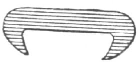
Fig. 319—Showing Clamp for Holding while Heating the Point
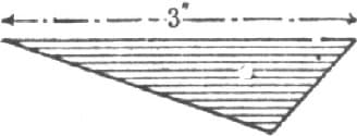
Fig. 320—Showing Point Used for Bottom of Lay
Laying a Plow.
To describe how I lay a plow, I will begin by calling attention to Fig. 321, which shows how a plow generally looks when brought to the smith to be laid and pointed. There is usually a hole worn in the plow back of the point in the throat, as in 1 in Fig. 321. I forge out a piece of steel of the shape shown in Fig. 322, making it very thick on the side from A to B and then from A to C; I then clamp it to the plow with tongs, as in D, Fig. 321, and as shown by the dotted lines. I next heat at E, weld rapidly, take off the tongs, bend the part F under, then put on plenty of borax and weld clear up. The plow is now solid and ready for the lay. I forge out a piece of lay steel of the shape shown in Fig. 323. It is simply doubled up at the point G; I forge then from H to I and J, and upset at H very heavy, to bring out the worn-off corner of the plow; I then lay it on the bottom of the plow as shown by the dotted lines in Fig. 324, clamp it on with tongs at K, put a heat on the point, weld rapidly, then take off the tongs and weld up solid as far back as the lay goes. The heat should be put at the back part of the lay, along the dotted line in Fig. 324, to make a good weld back there. If the job is properly done the share will be lengthened one and a half to one and three-quarters inches. Fig. 325 shows how the plow looks after laying, and the dotted line indicates its appearance before the laying. Most of the laying I do is on Diamond plows. In laying a new share, great care is required to keep it in shape.—By J. O. H.
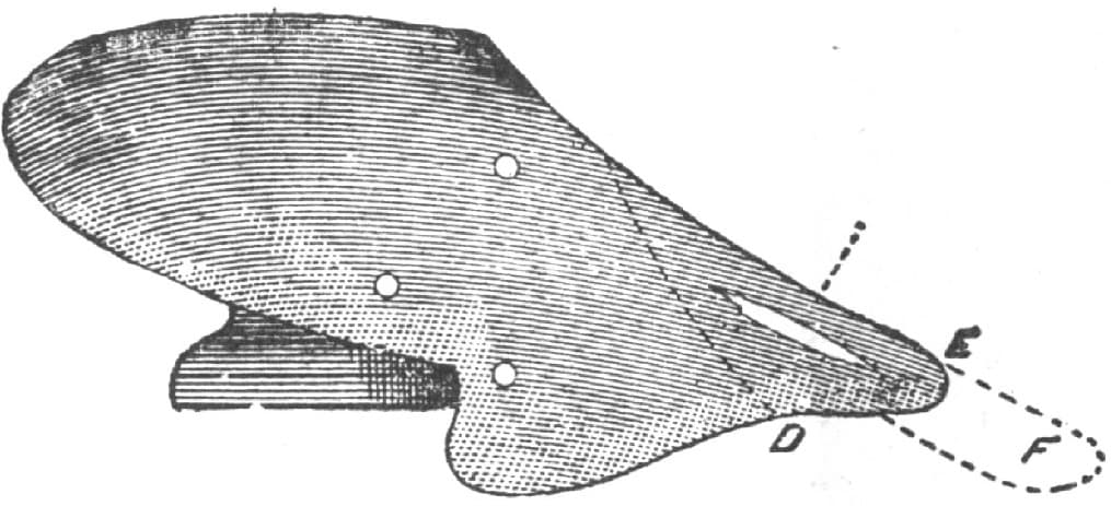
Laying a Plow by the Method of “J. O. H.” Fig. 321—Showing the Plow Before Laying and Pointing
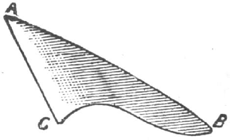
Fig. 322—Showing the Piece to be Clamped to the Plow
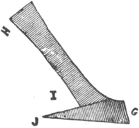
Fig. 323—Showing the Shape of the Lay Steel
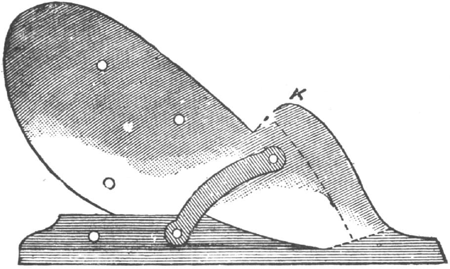
Fig. 324—Showing how the Steel is Laid on the Plow
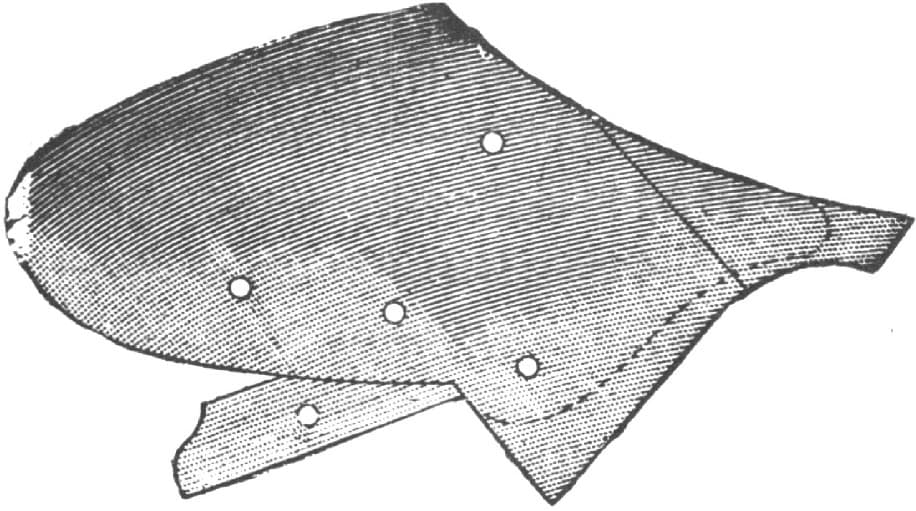
Fig. 325—Showing the Job Completed
Polishing Plow Lays and Cultivator Shovels.
Perhaps some of your readers would like to know a good way to polish plow lays and cultivator shovels. After pointing shovels and new or old lays I always grind them bright on a solid emery wheel about twelve inches in diameter, with a two-inch face. I then put them on the felt wheel and finish them off so that they look as if they had just come from the factory. The chief point to keep in mind in using emery wheels for a smooth surface like a plow lay is to have a wheel that is soft and elastic. You can never get a fine finish from a hard, solid stone.—By “SHOVELS.”
Laying a Plow.
PLAN 1.
In laying a common plowshare I make my lay of German plow steel about five-sixteenths of an inch thick on one edge, and as thin as I can hammer it on the other. I then sharpen the plowshare as sharp as the thin edge of the lay; then I strike all the point in separate heats. If I have no striker, I weld about three inches at a heat, being careful to get the back edge thoroughly welded down and level with the surface of the balance of the share. If the outer edge of the share is not thoroughly welded, this can be easily done by taking a heat on it while drawing the edge out sharp. If I have a striker, I weld about four inches at a heat, having the striker strike directly over where the edge of the share meets the lay, thus welding the edge of the share to the lay, while I weld the back edge of the lay to the share with the hand hammer at the same time.
The greatest trouble with most smiths in laying plows is that they leave their lay too thick at the back edge where it laps over the share, so the share gets too hot and burns before the lay gets hot enough to weld. I use common finely pulverized borax for a welding compound. A good way to test your heat is, when the lay is about to come to a welding heat, just lightly remove the burning coal from the top of the lay and lightly tap its edge along as it welds, keeping up a blast at the same time. This way of doing not only shows when the lay is in a condition to weld, but the welding is actually commenced in the fire, the share and lay thus beginning to unite as soon as it begins to come to a weld, and therefore is less liable to burn than if it were not settled by the light blows of the poker. I always leave the out edge of my lay as thick as possible until all is thoroughly welded. Then the plow is ready for the point; for points I use 11/2 × 1/2 inch German steel.
I get my point out with the back end as wide as the base it is for, and as thick as the base will permit. I let my point extend back from two to five inches, or sufficient to give the base the necessary strength at the point. I strike the point at separate heats, and when the point is thoroughly welded I work it out well in the throat with the pene of my hammer or fuller, then begin at the point to draw the shoe out, drawing it with a gradual slope from the back edge of the lay to the required edge, keeping the edge on a perfect level with the bar, and being careful to leave the heel of the share and the corners of the point on a straight line, sighting from the heel of the share to the point.—By J. MCM.
Laying a Plow.
PLAN 2.
To new lay steel plowshares, I select a piece of spring steel and heat one end to a high borax heat, then strike it with my hammer, and if it flies to pieces I put it aside. I don’t use high steel. In preparing my steel I partially weld a strip of hoop iron on the edge, leaving it so that where it is scarfed or chamfered the iron will be full with the edge of the steel. I then chamfer the share and weld as usual. It is surer to weld when iron is between the parts.—By J. U. C.
Laying a Plow.
PLAN 3.
Repairing plows forms a major part of the blacksmith’s business in the Pacific States from the first of October until the following May. I will therefore give my plan of “laying a plow,” and I hope by this means to draw the craft into a discussion of the subject, to our mutual benefit.

Laying a Plow by “Hand Hammer’s” Method. Fig. 326—Showing the Iron Bar drawn from Shin to Point
I will take a sixteen-inch plow for example. First cut a bar of iron 21/2 × 1/2 inch and about thirty inches long; cut on a bevel at one end to save hammering; take a heat on the beveled end; draw as in Fig. 326, from shin to point about ten inches long, and punch a one-quarter inch hole, as at A.
Second: Clamp the landside thus prepared upon the plow standard in the proper position (the plow being inverted), and with a slate pencil mark for the holes, which, when drilled, countersunk and squared to fit the bolts, can be bolted into place upon the plow.

Fig 327—Showing the Method of Cutting the Steel
Third: Take a slab of steel 6 × 1/4 inches, lay it on the plow, parallel with and against the lower edge of the moldboard, and with a pencil draw a line across the steel against the landside. This gives the length and angle at which to cut the steel, as at b, Fig. 327. Then lay the blade of a square two inches wide upon the steel, parallel with the line b, and draw a second line on the opposite edge of the square, which gives us the line c, parallel with and two inches distant from line b. Now find the center of the cross section and draw the line d, then trace with a pencil as indicated by the dotted line e, and upon this line heat and cut off, which gives you the pattern Fig. 328. Next heat at f, Fig. 328, as hot as the steel will bear, and grasping the pattern with both hands at g, g, g, g, strike the point h upon the anvil a few sharp blows, which will give you the “shape,” Fig. 329, after which draw to an edge, then heat as hot as the “law allows” the entire length and bend over a mandrel (lying down), the helper holding a sledge on the back of the pattern while you hammer along the edge until the curve is right to fit upon the landside and brace, and along the moldboard where it is designed to go. When cool place the pattern in position and mark for the holes 1, 2, 3, 4, as shown in Fig. 329. After these holes are drilled, countersunk, and fitted to the bolts, place the parts in position as in Fig. 330, and fasten with a bolt at I, and a rivet at J. Now you are ready for the last, though by no means least important or difficult operation, i. e., welding, for if you fail in this all is lost.

Fig. 328—Showing the Pattern

Fig. 329—Showing the “Shape”
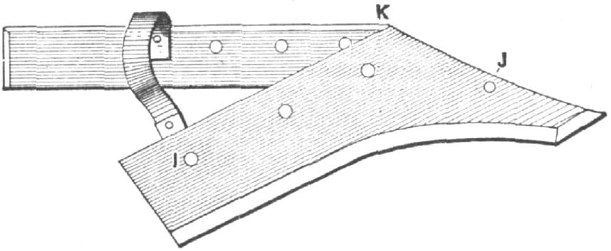
Fig. 330—Showing the Parts Placed in Position and Fastened
Finally: Place the work in a roomy, clean fire with the landside flat down, and heat red at the shin; then take it to the anvil and hammer it down close; return it to the fire, apply plenty of borax, and heat to a good welding heat, giving plenty of time to “soak”; then place it upon the anvil and have your helper catch hold of it at the top of the shin at K, Fig. 330, with the “pick-ups” and squeeze firmly to the landside while you weld with the hammer from the tongs down to the rivet. Next take a heat at the top of the shin where the tongs prevented welding and weld it down, after which weld from rivet to point. The slender point from h to l, Fig. 328, must be turned under; then weld up, which gives strength and shape to the point. Now straighten up the edge, and temper the bolt on the plow.—By HAND HAMMER.
Laying, Hardening and Tempering Plows.
I will try to give my practical experience in laying, hardening and tempering the Casaday sulky plowshare; a plow generally used in Texas for breaking old land, and sod as well. When the shares are new they cut from twelve to fourteen inches, and are five and one-half inches wide, measuring from twenty to twenty-five inches from heel to point on the edge. When they are brought to the shop for laying, they resemble Fig. 331 of the accompanying illustrations, measuring from three and one-half to four inches in width. The first thing I do is to lay a piece of iron on the point, which, when shaped looks like Fig. 332. This makes the point of sufficient length and strength to receive the lay, which I make of German or hammered steel, one and one-quarter inches wide by three-eighths of an inch thick, and shaped as in Fig. 333. The heel of the lay is upset to make it heavier and wider in order to supply the deficiency of metal at the heel of the share. I then draw the upper or inside edge of the lay to about one-eighth of an inch, as I do also the edge of the share, and next drill two small holes in the share; one at the heel, the other about midway between the heel and the point of the share. I then place the lay in position on the under side of the share, mark and drill the lay, and rivet it on. This will hold it in position. I then put it in the fire and heat until I can bring the lay and the share close together, and then turn the lay back from A, the top of the share, as shown at A, Fig. 333, the object being to thicken the steel, which in many cases is worn quite thin, and requires this extra metal to draw and shape the point. The dotted lines show how the broad or fan-tail points of the lay fit the share when turned back. I next weld from point to heel, and if when welded the back of the share will not fit the moldboard, I heat the whole share, and while it is hot set it up edgewise on the anvil, and strike it on the edge, which will bring it straight. I then begin to shape it at the point, and draw the edge, using the pene of the hammer, or, if the face is used, I allow the edge to project over the round edge of the anvil, to prevent stretching on the edge, which would cause it to curve on the back. When finished and properly shaped it will look like Fig. 334, and be from one-half to three-quarters of an inch wider than the original share. Before drawing it to an edge, I carefully examine it to see if there are any skips or failures, and if such are found, heat, raise the edge, and insert a thin piece of hoop iron, allowing it to project slightly beyond the edge of the skip. Take a light borax heat and it will stick.

Fig. 331—Showing the Appearance of the Share when Brought to the Shop for Laying

Fig. 332—Showing how the Iron is Laid On
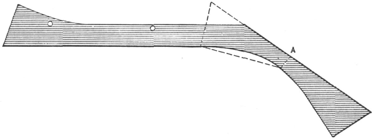
Fig. 333—Showing how the Lay is Shaped

Fig. 334—Showing the Share Completed
With the share finished the next thing in order is hardening and tempering, which if done in the ordinary forge of the country shop requires practice for success. First have a good clean fire of well coked coal, keep up a regular, steady blast as if taking a welding heat, put the point in first, allow it to get nearly red, as it is the thickest, move it through the fire gradually to the heel, and continue to pass it back and forward through the fire until you have an even heat from point to heel about an inch back from the edge. When you have the proper heat, have at hand a trough two and one-half feet long, and holding the share firmly in tongs immerse the edge in the water for an instant. Raise the edge or heel out first, allowing the point to remain a second longer because it has more heat than the edge, but taking care to have heat enough remain in the share to draw the temper to a blue. Have a brick with which to rub the edge, that you may be able to see when you have the proper temper. If there should not be heat enough in the share to do this, hold it over the fire again. Be careful to draw the temper as evenly as possible, for if it has hard and soft places it will wear into scallops.—By D. W. C. H.
Laying Plows.
I have been laying plows more or less for sixteen years, and in describing my method I will first deal with the slip share. I first make a lip as shown in Fig. 335. This lip is made of iron one-half an inch thick, and of proper width, forged down to the shape shown, with a bevel for right or left as desired. The joint A must be fitted snugly to the plow, so that when bolted on it will be level with the bar on the bottom, and will neither work up nor down at the point. In drilling the hole in the lip, care must be taken to have the bolt draw the joint together. When finished, bolt on the plow, and swing the plow up by the end of the beam, letting the handles rest on the shop floor. Cut the steel as in Fig. 336, using five-inch steel for twelve-inch plows, five and one-half inch for fourteen-inch, and six-inch for sixteen-inch plows. Heat the steel at B B hot as the law allows, and bring the point around to the proper angle, and to the shape of Fig. 337. From C to C the length should be nine inches for a twelve-inch plow, ten inches for fourteen-inch, and twelve inches for a sixteen-inch plow. The edges of the shares should be drawn with the face to the anvil, making the bevel underneath. Cut and fit to the lip and mold-board as snugly as possible. It is a good plan to have the point of the share longer than necessary, so it can be turned under the back when beginning to weld on. When your lay is in the exact place, mark the bolt holes and drill and countersink, then bolt the share to the plow with a crossbar bolt. Take the landside, crossbar, and share all off together, just as you would a solid bar, and with a nice, large, clear fire weld up the two first heats, then unbolt the share and lip, and take off and finish welding to the top; now bolt on the landside and refit the share, if you have got it out of shape in making the last welds.

Laying Plows by the Method of “R. W. H.” Fig. 335—The Lip

Fig. 336—Showing how the Steel is Cut
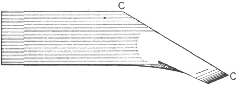
Fig. 337—Showing the Shape Given to the Point
Now I have described how I lay slip-lays. Solid bars or landsides I treat in the same way, for all the difference between the two is that there is no lip to make separately in the solid landsides. In laying the steel on the plow to mark the holes, I let it project over the bar one-eighth of an inch, which gives metal enough to dress a sharp corner in finishing.—By R. W. H.
Making a Plowshare.
In making a plowshare, I first get out my steel like Fig. 338. Then I turn the point, as in Fig. 339. I do this so that when it is bent back the point will have the same angle as the edge of the share and will not be square or like a chisel, as it will if left straight and bent back square in the old way. I next bend the point down and bring it back square with the shin. I next forge out the bar, and when about finished I take a light heat, and clamping it in the vise, draw a flange on the lip on the inside of the bar as in Fig. 340. I now slip the point of the bar under the point of the share which is bent back, and with a pair of tongs I clamp the bar fast to the share by catching over the share and under the lip on the bar, as in Fig. 341, and in this way avoid trouble while welding. I begin at the point, and when near the top I turn the share over and with the pene of my hammer weld down the lip first, and then with the face of the hammer I strike on top of the share and never have failed to make a good weld in this way.—By L. H. O.
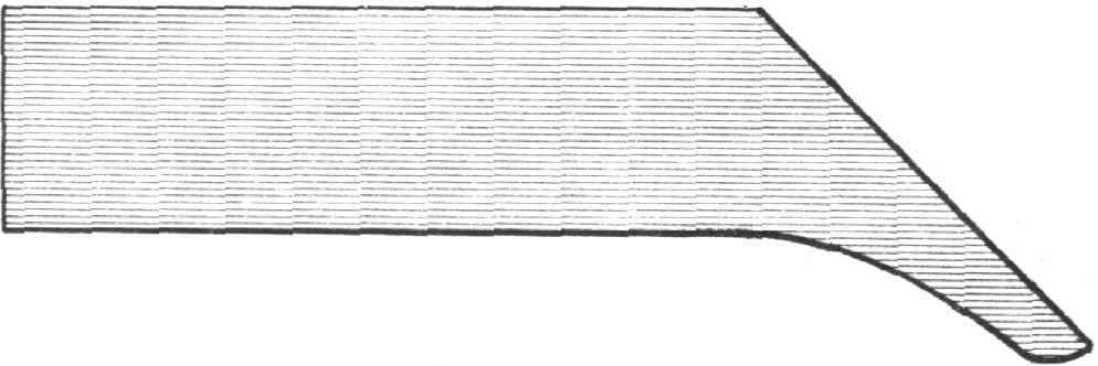
Making a Plowshare. Fig. 338—Showing how the Steel is Shaped at First
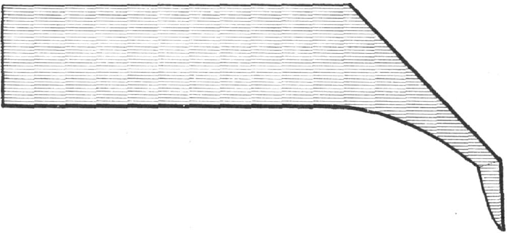
Fig. 339—Showing how the Point is Turned

Fig. 340—Showing how the Flange is Drawn
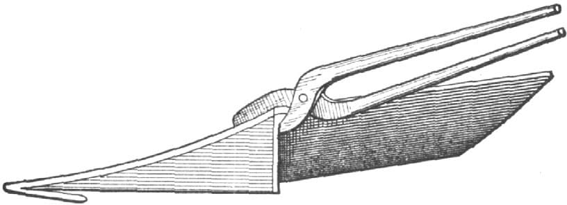
Fig. 341—Showing how the Bar is Clamped to the Share
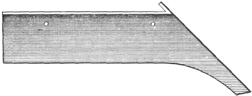
Fig. 342—Showing the Share Completed
How to Sharpen a Slip-Shear Plow Lay.
Take iron 1/2 × 3/4 inch square, thirty inches long, bend it in the center and bring the sides parallel with each other three-eighths of an inch apart, and weld the ends. This piece, shown in Fig. 343, is to keep the lay from springing up in the center. I then bolt this piece to the bottom of the lay with the three bolts taken out, or with new ones, as shown in Fig. 344, and then sharpen the edge of the lay from point to heel. If there are no rocks where it is used I draw well back and very thin, and leave as few hammer marks as possible on top. I always set the edge from point to heel perfectly level with the landside on a level board or stone, not by just sighting with my eye. A level plow lay is bound to run well, and it will tickle the farmer all over when it runs well.—By G. W. P.

Sharpening a Slip-Shear Plow Lay. Fig. 343—The Piece which Prevents the Lay from Springing
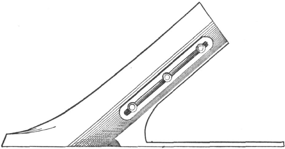
Fig. 344—Showing how the Piece is Bolted
Welding Plow Points.
When making new points or welding old ones that have ripped, I turn the point bottom upwards, pour in a handful of wrought iron shavings along the seam, then a little borax on top of them, and lay the point in the fire just as it is. If care is taken to heat the bar a little the fastest, the shavings will come to a welding heat much sooner than the point, and will be like wax when the share and bar get to a welding heat. Then with a light flat pened hammer, Fig. 345, I settle the share on the bar, turn it over and with the flat pene smooth down the melted shavings, making a strong and neat job. When the point is ready for tempering I lay it down and allow it to cool, then I heat the edge evenly from end to end and set it in the slack tub edge down, taking care that the edge touches the water evenly from end to end. By this means I make a point solid and unsprung.—By J. W.

Fig. 345—Hammer Used by “J. W.” in Welding Plow Points
How to Put New Steel Points on Old Plows.
I have thought that someone would like to know how to make plow points last on rocky or clay land in Maine. The farmers use cast-iron plows mostly, and a new point don’t last long.
To help the poor farmer and myself just a bit, I new-steel old points by the following method: I use old carriage springs or old pieces of sled shoe steel, if I have them. First, take a piece of steel 1/4 × 13/4 × 9 inches long for medium size plow, draw down one end thin, about one-eighth of an inch, and punch a five-sixteenths inch hole one inch from thin end, punch second hole four inches from first hole. Cut out the other end with a gouge-shaped chisel, as shown at A, in Fig. 346. Measure three inches from gouge cut end, and bend back, as shown at B, Fig. 347. Cut off four and one-half inches of same size steel, draw down one end thin, say to one-eighth of an inch, and punch one-fourth inch hole in thick end as at C, Fig. 348. Punch one-fourth inch hole in long piece, through the fold, rivet the two pieces together as in Fig. 349. Take welding heat on the parts that are riveted together and draw as in Fig. 350. Take the new point while hot and fit it to old one, work the first hole on old point drill, countersink and rivet on your new point; drill the second hole from top through cast iron and steel, countersink, be sure to cut the rivet plenty long enough to rivet, put it into the hole, and batter up the end just so the rivet won’t fall out, then heat the point and rivet while the point is hot; fit new point to old one nicely while hot. If the old point did not carve the ground enough drop the end of the new point so as to be on a line with the bottom of plow as shown at E, Fig. 351. Let the job cool before hardening the point. When done the new point should be from two and one-half to four inches long from the end of old point; for rocky ground they should not be as long as for clay. I charge from forty-five to seventy-five cents per point, according to size of plow, and the farmers say that a point fixed this way will do better work and outwear two new cast-iron points, which cost from sixty cents to one dollar each, thereby making quite a saving.—By GEO. H. LAMBERT.

How to Put New Steel Points on Old Plows. Fig. 346—Showing how the First Piece of Steel is Prepared

Fig. 347—Showing how First Piece of Steel is Bent

Fig. 348—Showing Second Piece of Steel

Fig. 349—Showing how the Two Pieces of Steel are Bolted Together Ready to Draw Out

Fig. 350—Showing the Two Pieces of Steel seen in Fig. 349 Drawn to a Point
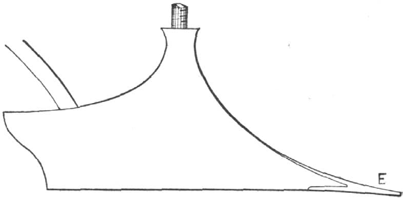
Fig. 351—Showing the Steel Point on the Plow
Pointing Plows.
I first cut the point out of crucible steel one-fourth of an inch thick, as in Fig. 352. I draw the point to a thin edge as far back as the dotted line extends on that edge, then double the point back at A for right or left hand, as desired. I also thin out the point C. I forge down close, and after thinning the old point out, drive on as in Fig. 354, where the part B is shown on top of the point. In Fig. 353 the point is shown applied to the plow underneath. I next, with a large clean fire, weld on, commencing at the point, welding up the bar as far as the point extends, then having part C close to the share, weld up solid, draw out to make a full throat, and finish. Fig. 355 shows the point completed. This makes a very durable point, and always looks well if properly put on.—By R. W. H.
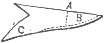
Pointing Plows, as done by “R. W. H.” Fig. 352—Showing the Point
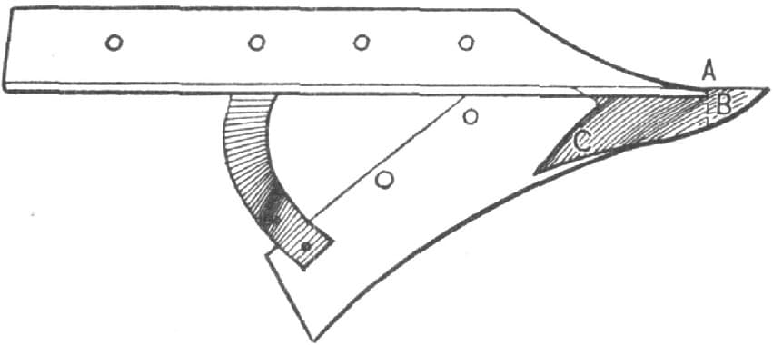
Fig. 353—Showing the Point Applied to the Plow Underneath
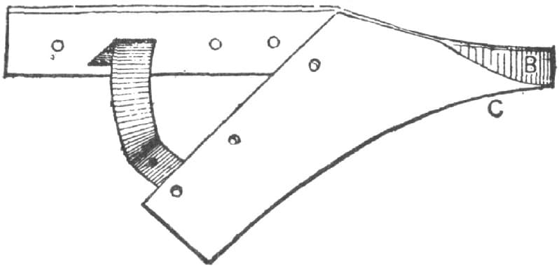
Fig. 354—Showing the Part B on Top of the Point
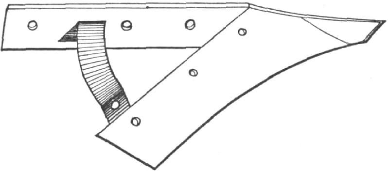
Fig. 355—Showing the Point Completed
Tempering Plow Lays and Cultivator Shovels.
I have a recipe for tempering plow lays and cultivators which I think splendid. It is as follows: 1 lb. saltpetre, 1 lb. muriate ammonia, and 1 lb. prussiate of potash. Mix well, heat the steel to cherry red, and apply the powder lightly. When the oil is dry, cool in water. This leaves the steel very hard and also tough. The mixture is also good to case-harden iron and to make a heading tool.—By A. G. B.
Sharpening Listers.
The prairies of the West are plowed, harrowed, and planted in corn with a single machine called a lister, and it is therefore probable that the method of sharpening it will be of interest to some readers.
My way of doing the job is to take off the lister shore, Fig. 356, and after making the brace shown in Fig. 357, bolt this brace on the bottom side, so that the bolts in the back end of the lay will pull it a little. Just here I will add, that as no two lister lays are alike, it is necessary to have a brace for each one, and it is advisable to mark each brace made, so that it can be used whenever the lay it fits comes back to the shop again. The next thing to do in the sharpening operation is to heat at the point and draw thin for three or four inches on one side. Then change to the other side and draw on that two or three inches more than you did on the first side taken in hand. Continue changing from one side to the other and testing it on a level surface. It can be kept level and the point can be kept down, as the latter can be turned up easily by hammering on the bottom side.
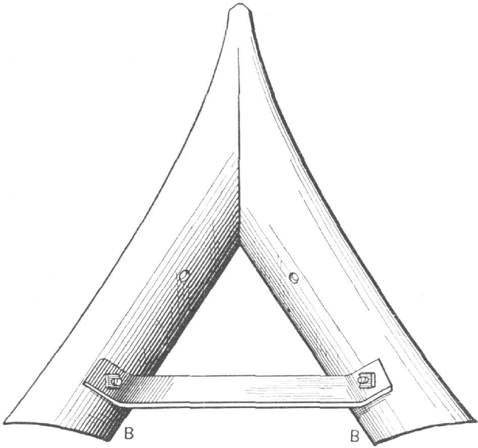
Sharpening Listers. Fig. 356—Bottom View of the Lister Shore

Fig. 357—The Brace
Be sure to keep your lay level as you go on, and also keep it smooth on the top side. In some localities it must be polished to make it scour. Always let the lay get cold before you take the brace off, and then it can be put in place again without any trouble.—By G. W. PREDMORE.
Notes on Harrows.
In a harrow I lately made I inserted lengths of one-half inch gas-pipe between the wooden bars, as sleeves on the rods or bolts, as shown in Fig. 358, so that all could be drawn up tight. It is quite a success. A good plan is to mortise in a light strap of iron, say 1 × 1/4 inch, directly under the top strap, and bolt or rivet through, as at A in Fig. 359, all nuts on top, to keep the ground side smooth. Fig. 360 is a top view of the parts shown in Fig. 359.

Notes on Harrows. Fig. 358—Showing a Method of Utilizing Gas-pipe in Making a Harrow

Fig. 359—Showing How the Light Strap is Mortised in and How the Riveting and Bolting is Done

Fig. 360—Top View of the Parts Shown in Fig. 359
The narrow hinge shown in Fig. 359 is common, and can’t be beaten. It allows each section to have a slight independent motion, can be unhooked at once by raising one part, and is easily folded over for cleaning.
I don’t think it necessary to mortise the teeth holes out square, as is often done, round ones do well enough. A good size of tooth for general work is 1/2 × 5/8 inch (steel). This holds well in a five-eighths inch round hole. A round hole takes some driving, but I put a one-fourth inch bolt, or rivet (“wagon-box” head) and burr, back of each tooth. It may interest some to learn that in certain parts of Europe an iron tooth is inserted from below, having a shoulder to fit against the bottom of the bar and a thread and nut on top to hold it. It is pointed with steel, and when worn goes to the smith, like a plow, to be laid.
I used a harrow of two-inch iron gas-pipe for many years, and the teeth (one-half inch square steel) held perfectly in round holes. The objection to it was that the cross-pieces being so low gathered up clods, etc.
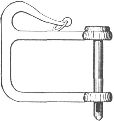
Fig. 361—Showing the Method of Attaching the Doubletree
The best method of attaching the doubletrees is, I think, by a clevis combined with a safety-hook, as shown in Fig. 361.—By WILL TOD.
Making a Bolt-Holder and a Plowshare.
A handy bolt-holder which I have occasion to use is made of two pieces of 3/8 × 3/4 iron or steel, shape, put together as shown in Fig. 362. One piece is made with a flange to hinge into a slot, which is seen at A Fig. 362. The notches are made different sizes so as to hold bolts of different sizes.
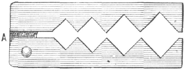
Making a Bolt-Holder and Plowshare. Fig. 362—Showing Bolt-Holder Complete
With this tool one can hold any plow bolt that has a countersunk head, and would be spoiled by the vise. The slot and rivet act as a hinge to take in large or small bolts.
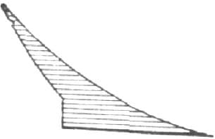
Fig. 363—Showing Piece of Iron as Used by “J. W. J.” in Fitting Plowshare
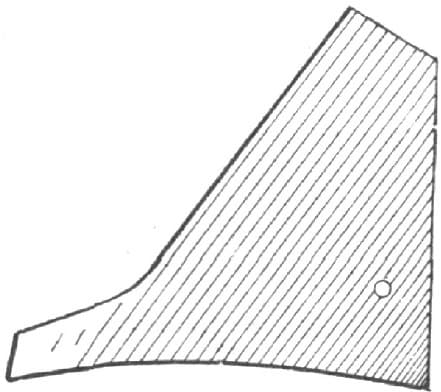
Fig. 364—Fitting Plowshare
I have a great many shares to make for plows, and every smith knows how hard they are to fit. Instead of staving them, I take a piece of iron, as shown in Fig. 363, and weld on to the share, Fig. 364. After this is welded on it is an easy matter to fit it with a sharp chisel. I use five-sixteenths inch steel.—By J. W. J.
Making a Grubbing Hoe.
PLAN 1.
The following is my plan of making a grubbing hoe or mattock. Take a piece of iron 2 × 1/2 inch, and about twelve inches long, cut it as at A, Fig. 365, bend open together and weld up solid to an inch and one-half of one end, then split open and put the steel in as at Fig. 366, then weld the other end for one and one-half inches together; this will leave about two inches not welded as at B; then take a heat not quite hot enough to weld at B, and forge as at C, Fig. 367, and D, leaving the eye, C, Fig. 367, closed. Then take a piece as before like Fig. 365, only ten inches long, and weld solid together throughout, and forge as Fig. 368, E. Then take a good welding heat on both pieces and weld as at F, Fig. 369, with steel in as G, then forge and finish up as at Figs. 370 and 371. This makes a good strong mattock, and is the only way I know of to make one, unless it is to weld two pieces together and form the eye, and then twist for the hoe end.—By EPH. SHAW.

Making a Grubbing Hoe by the Method of Eph. Shaw. Fig. 365—Showing the Iron Cut for Bending Open

Fig. 366—Showing the Piece Split to Insert the Steel
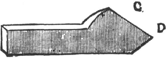
Fig. 367—Showing how the Iron is Forged
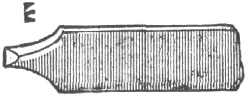
Fig. 368—Showing how the Forging is done at G, on the Other Piece

Fig. 369—Showing how the Two Pieces are Welded

Fig. 370—Showing the Finished Mattock

Fig. 371—Another View of the Finished Mattock
Making a Grubbing Hoe.
PLAN 2.
To make a grubbing hoe, take iron 3 × 1/2 inch, cut as shown in Fig. 372, draw out the ends, bend at A to a right angle, bring B B together, as shown in Fig. 373, and then weld. This is an easy job, and the result is a good hoe.—By SOUTHERN BLACKSMITH.
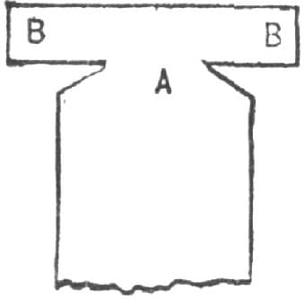
Making a Grubbing Hoe by “Southern Blacksmith’s” Method. Fig. 372—The Iron Cut and Drawn
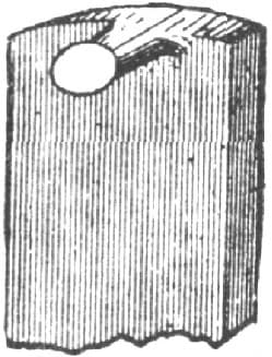
Fig. 373—The Iron Bent to Shape
Forging a Garden Rake.
The question is often asked, Can forks be made successfully of cast-steel? I can always forge better with cast-steel than with any other metal. I have made a garden rake of cast-steel and it was a good, substantial job. It is done as follows: Take a piece of steel one-fourth or five-sixteenths of an inch thick, lay off the center as in Fig. 374, then punch a hole about as far from the center as is necessary to give stock enough to turn at a right angle for the stem to go in the handle. Then cut out with a sharp chisel as marked in the dotted lines A. Then lay off the teeth B B, punch or drill holes and cut out. The end pieces C C can be turned out straight and drawn out well. After the holes and the pieces are cut out, to separate the teeth turn each tooth (one at a time) at right angles, and draw out to the desired size. Then straighten it back to its place, and so proceed until all the teeth are drawn. By using a tool with holes in it to suit the tooth you can give it a good finish on the anvil.—By CONSTANT READER.

Forging a Garden Rake. Fig. 374—“Constant Reader’s” Plan
Making a Double Shovel Plow.
I will describe my method of making a double shovel plow: I first make the irons. The shovels should be five inches wide, twelve inches long, and cut to a diamond or a shovel shape, as the customer desires. After drawing, bend a true arc from point to top, on a circle of twenty-two inches in diameter. The plow will then, as it wears away, retain the same position it had when new. I make the faces of plows to suit customers. Some prefer them flat, others want them oval, and some want a ridge up the middle. In the latter style a cross section of the plow would look as in Fig. 375.

Making a Double Shovel Plow. Fig. 375—Cross Sectional View of a Ridge-Faced Plow
The next thing to be done is to make four brace rods, two one-half inch, and two 1/2 × 15 inches. There should be ten inches between the center of the eye and the nail hole. I cut threads on the ends of the one-half inch rods, and punch nail hole in end of three-eighths inch rods. I then take three bolts, two one-half inch, one 3/8 × 3 inches long; one of the one-half inch bolts should be eight inches, and the other seven and one-half inches long. The clevis comes next. I take two pieces of one-half inch round iron, ten inches long, flatten one end of each piece, punch three-eighths inch hole, lay the flat ends together, weld the round ends and bend to shape, when the clevis will look as in Fig. 376. I bore a hole in the end of the beam to admit the point of the clevis. This keeps it firmly in place. The irons are then finished. In beginning on the wood-work, I take two uprights or standards, one three and one-half feet long, and three and one-fourth inches in the widest part, and two inches thick; the other is of the same dimensions, except that it is somewhat shorter at the top end. I make these as in Fig. 377. The beam is made four feet, three inches long, three and one-half inches wide in the widest part, and two and one-half inches at the point. I bore three holes in the wide part, two holes being one-half inch, and one three-eighths inch, and each being twelve inches from center to center, as shown in Fig. 378. After making the handles I fit the shovels to the uprights, and then take two strips of plank 1 × 2 inches, one strip fifteen inches, the other sixteen inches long, and nail blocks on one end, as in Fig. 379, and nail them down to the floor so that the ends of beam will rest in them, as shown in the illustration, resting the front end on the short piece. I lay the beam on, take an upright, stand it up by the side, as in Fig. 379, and adjust until the shovel stands on floor to suit me. I let the shovels stand rather flat on the floor. They will run better when sharp, but will not wear as long without sharpening. I put the pencil through the hole in beam, and mark the place where the hole is to be bored in the upright pieces. I bore brace holes and take a seven and one-half inch bolt, and put it through the long upright from left to right.
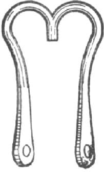
Fig. 376—The Clevis

Fig. 377—Showing the Standard

Fig. 378—The Beam
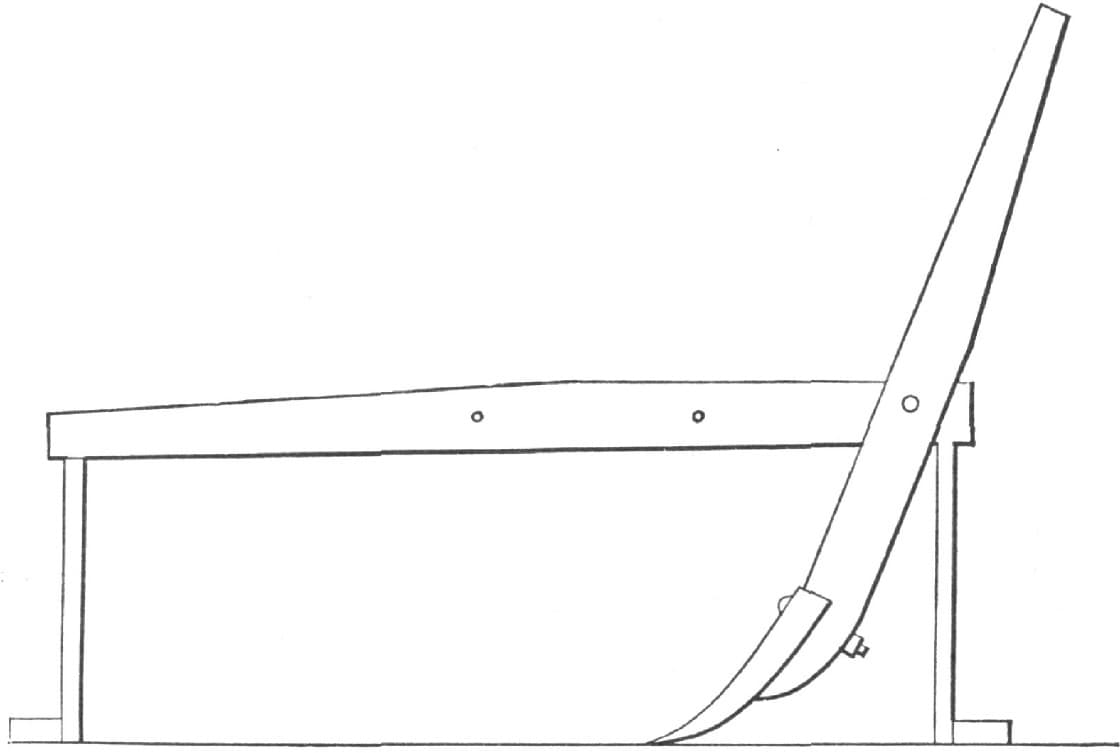
Fig. 379—Showing the Method of Adjusting the Position of the Standard
The block put on should be 3 × 3 inches, and two and one-half inches long. Some use iron, but wood is as good and makes the plow lighter. I put the bolts through the beam and put on a three-eights inch brace and a nut. I put an eight-inch bolt through the short upright block and beam from right to left, and put a one-half inch brace through the hole in the upright, as shown in Fig. 379. I put the eye of the one-half inch brace on the bolt and also use a three-eighths inch brace. I use a one-half inch brace in the front upright, and also one bolt. I screw the nuts up, bend three-eighths inch brace down under the beam and against uprights, rivet the end to the upright, and the plows will then stay well apart.
In placing the handle on the beam I ascertain the height wanted on the upright, bore an inch hole through the same, and fit the rung in so that it projects three inches to the left of the upright. The right handle is put on so as to come on the outside of the front upright. I notch the upright to fit the handle and bolt them together with a five-sixteenths inch bolt. Then the clevis is put on and the plow is ready for painting. Fig. 380 represents the ordinary shovel, and Fig. 381 shows the diamond-shaped shovel. The finished plow is shown in Fig. 382.—By C. JAKE.
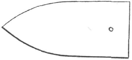
Fig. 380—The Shovel
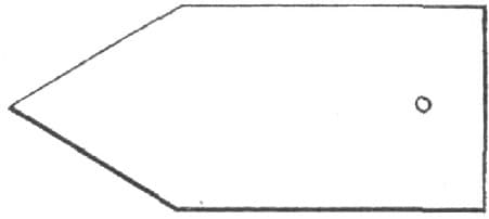
Fig. 381—The Diamond-Shaped Shovel
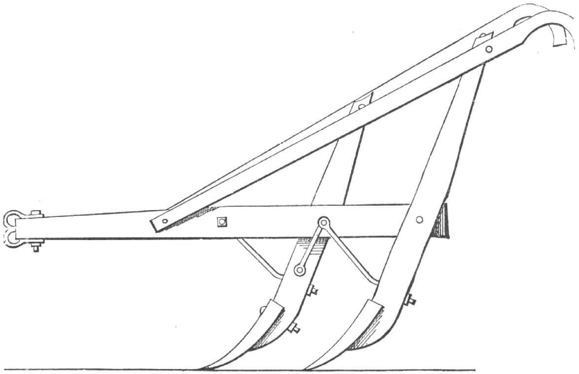
Fig. 382—The Finished Plow
Pointing Cultivator Shovels.
PLAN 1.
We that labor for farmers must know how to do work on farm implements and machines, and so there may be many who would like to know a good way for pointing cultivator shovels. My plan is as follows:
I take a piece of spring steel about six inches long and one and one-half inches wide, and draw it out from the center toward each end to the shape shown in Fig. 383. I then draw out the straight side A to a thin edge and cut through the dotted line nearly to the point. I next double around as in Fig. 385 and take a light heat to hold it solid. I then take the old cultivator shovel, as illustrated in Fig. 384, straighten it out flat, lay the point on the back side, take a couple of good welding heats, and finish up to shape as in Fig. 385, making virtually a new shovel.—By A. M. B.

Pointing Cultivator Shovels by the Method of “A. M. B.” Fig. 383—Showing the Shape to which the Steel is Drawn
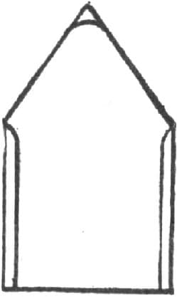
Fig. 384—Showing the Old Cultivator Shovel

Fig. 385—Showing the Steel After it has been Cut into and Doubled Around
Pointing Cultivator Shovels.
PLAN 2.
I will describe my way of pointing cultivator shovels, and I think it is the best and most economical I ever tried. Take a piece of one-quarter inch plow steel two and one-half inches wide, cut it as shown in Fig. 386, and forge it into the shape shown in Fig. 387. Then you will have a point with just the right amount of steel in the right place and with none wasted. I always mark the whole bar with a dot punch before I commence cutting the points.—By W. L. S.
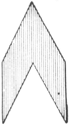
Pointing Cultivator Shovels. Fig. 386—Showing how the Steel is Cut
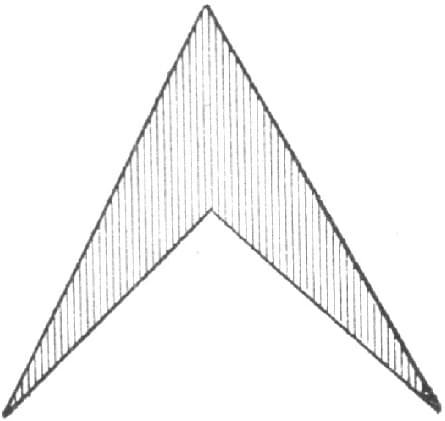
Fig. 387—Showing the Point after the Forging
Pointing Cultivator Shovels.
PLAN 3.
I cut out my points in one piece as shown in Fig. 388, using good crucible steel. Then I take the shovel to be pointed and draw its point, then half way up each edge I also draw the points shown in Fig, 388, where they lap on to the shovel edge, and cut them to fit under the point of the shovel to be pointed, as shown in Fig. 389. In getting the point in place clamp it with a pair of tongs on the right side of the shovel, put in the fire on the left side, with the face of the shovel up; have an open, clear fire ready, put on borax, and let the heat come up slowly, so as not to burn the point underneath. A fan blower is better for this purpose, as you can regulate it to any degree of blast. After welding each point, take a light heat and tap the thin edge of the shovel down snug upon the point and lay it flat in the fire, face up; then take a wide heat (with plenty of borax) over the entire point and weld down solid with quick blows and with a hammer a little rounded on the face. Draw the edges out thin and hold the piece on the anvil so as to bevel from the bottom, leaving the top of the shovel level, as in Fig. 390. After finishing, heat to a cherry red all over, and plunge it in water edgeways and perpendicular, holding it still in one place till cool, then grind the scale off of the face and polish it on an emery belt. Shovels pointed in this way are almost as good as new, and will scour and give perfect satisfaction.—By R. W. H.
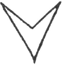
Pointing Cultivator Shovels. Fig. 388—Showing the Point
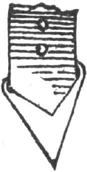
Fig. 389—The Point Adjusted Ready for Welding
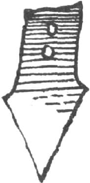
Fig. 390—The Finished Shovel