CHAPTER II
TIRES, CUTTING, BENDING, WELDING AND SETTING
Tiring Wheels.
The old-time blacksmith, who heated his tire to a bright red heat, after having given one-fourth to three-eighths of an inch draw to his tire, then deluged the rim with water to prevent its being burned up, would be skeptical as to the usefulness of a tire that is heated to, without reaching, the slightest shade of red, then cooled with a sponge, and water applied to the tire without wetting the wood; but if he looks back to the wood shop he will find that he was altogether in fault. With rims driven on that do not set snug up to the shoulders, there must be something done that will correct that fault, and the tire must do the work, but there never was any need of heating the tire as hot as they were accustomed to. Wheels that are well made have all the dish in them that is required, and any draw in the tire that is more than enough to set the metal snug up to the wood and tighten the ends of the felloes is useless. It is not a part of the blacksmith’s work to put the dish in the wheels, but it is the duty of the blacksmith to set his tire in a manner that will adapt it to the locality where it is to be used.
Wheel manufacturers season their timber thoroughly; unless they do so they cannot guarantee its durability. If the wheel is to be used where the natural condition of the atmosphere is dry, the tire can be set so as to hug the rim very tight; but if the wheel is to be used where the conditions of climate are different, the set of the tire must be regulated accordingly. Very many wheels are tired for shipment abroad; if the blacksmith sets the fire on these as close as he would were they to be used in New York, he will learn to his sorrow that he has made a blunder. The wood will expand while in the hold of the vessel, and the spokes will, if light, spring, or, if heavy, the felloe will bulge. The tire is simply a binder to the wheel, and when it is so set that it holds the wood firmly into the position designed it is in condition to perform its work thoroughly.—Coach, Harness and Saddlery.
Tire-Making.
The first thing necessary in making a tire is to see that it is straight, especially edgewise. The face of the tire should be straight before going into the bender. There are more tires and wheels ruined by the tire being bent for the wheel with crooks in the tire edgewise than in any other way in tire-making. Some seem to think the crookedness can be taken out more conveniently after the tire is bent, but this is a mistake. It is almost impossible to take it out after it is bent, because hammering will cause the tire to become flared, like that of a barrel hoop at the parts hammered on. And how would it look to put it on the wheel with either the bends or flare in the tire? Of course, in this case the tire is ruined, and so is the wheel. It is, of course, forced into the same shape as the tire. This kind of tire-making is more apt to be done by smiths who have no machine for tire-bending. Such tire-making is disgraceful, but it is common. The best way I have discovered to straighten the face and edge is to procure a good sized log, about eight feet long, and give it, either by sawing or hewing, a nice face. Then, after the tire-iron is drawn by hand as straight as possible, I take it to this log, and by the use of the sledge-hammer pound out the crooks. After all this I often find the part that was bent considerably twisted, and this is a thing I dread to see. Small a thing as it seems to be to remedy, it is not easy. The twist can be taken out by the use of a blacksmith’s large vise and a large wrench made for the purpose. If the twisted parts are made a little hot, the job is easier done. Some smiths seem to think that all this is too much trouble and takes too much valuable time, so make the tire just as the iron may fall into their hand, hoping the dishonest job may never be discovered.—By F. F. B.
A Simple Way of Measuring Tires.
I would suggest, as an easy way to measure tires, the following plan:
Let A, in Fig. 67, represent a section of the tire; now start at B and run over the tire with the measuring wheel and it comes out at C, as the tire is, say, half an inch larger than the wheel. Now, take a pair of dividers and open them to the extent of ten or twelve inches, or, better still, take a piece of stiff quarter-inch wire and bend it to the shape shown in Fig. 68. Then the points are not so liable to be moved by an accidental fall on the floor. Place one point at C, then take a center punch and make a mark where the other point touches at D, and also at B. Now heat and shrink or weld between B and D, and then, by placing the dividers in B or D, you can instantly tell whether you are right or not. If the tire is a little too short it can be drawn without reheating, whereas if you had to run it with the measuring wheel it would be so cold that reheating would be necessary. I think that by adopting this plan a smith can save an hour or more on a set of tires, and time is money.—By A. M. T.
A Simple Way of Measuring Tires. Fig. 67—Section of the Tire
Tiring Wheels.
After seeing that the tire iron is clear of twists and kinks, I lay it on the floor of the shop, then take up my wheel and set the face of it on the tire at one end of it. I next draw a pencil mark on the side of the rim exactly at the starting point at the end of the tire, and roll on the tire until the mark of the rim comes again to the tire. I then draw a mark across the tire, one and seven-eighths of an inch beyond the mark on the rim.
Fig. 68—The Wire Measurer Bent to Shape
I make this allowance provided the iron is five-eighths of an inch thick. This thickness is most commonly used on two-horse wagons. If the tire is greater or less in thickness, I would allow more or less, according to the thickness of the iron.
The height of the wheel need not be considered in allowing for the shrinkage, as a short bar shrinks just as much as a longer one. Some will think one and seven-eighths of an inch is more than is necessary to allow for shrinkage, but if they will observe this rule, they will find it almost correct. To allow more makes waste, and to cut it shorter ruins the wheel. For a hind wheel I give about nine-sixteenths of an inch draw, for a front wheel about seven-sixteenths. This is a matter which depends altogether on the condition of the wheel.
Some blacksmiths say a tire should not be made hot enough to burn the wood. This idea might do with small tires such as buggy or hack tires, but not with large tires. I make my tire very hot and cool it quickly. If I do not make the tire hot enough to burn the wood, I would just draw them on and set them aside, and let them have their own time to cool off. —By F. B.
A Cheap Tire Bender.
A cheap tire bender, which may be found very useful in many country shops, is shown by Fig. 69. A in the drawing indicates a section of a two and one-half inch plank. The part B is a segment of a three-foot six-inch circle. It is secured to a post with spikes, and the iron strap E E, two by two and one-half inches, is fastened to the block A and to the post in such a way as to leave at D a space of one inch between the strap and the block. By bending the tire slightly at one end and inserting this end under the strap at D, the process of bending can be continued and finished easily and rapidly. —By R. C.
Fig. 69—A Cheap Tire Bender, as Made by “R. C.”
Welding “Low-Sized” Tires.
Smiths sometimes experience a good deal of trouble in welding “low-sized” tires, from the fact that they are unable to take a full heat on more than half of the point to be welded. The following is my plan for obviating this difficulty. In Fig. 70, A represents the back upper wall of the forge. B is the hood or bonnet projecting over the tuyeres; D indicates the position of the tuyeres, and C is the upper section of the hearth. Fig. 71 represents the plate or anchor on which the brick composing the bonnet rests. To make it I took a piece of old tire two inches wide and about three-eighths of an inch thick, and first bent it on the edge so as to be rounding at the point H, and described a part of a circle eighteen inches in diameter, leaving the space G just fourteen inches in the clear, and from the corners E E to H just thirty-eight inches. I then turned down the lugs or corners F F eight inches, so as to catch on four bricks, and punched a hole at H for the insertion of the bolt P, Fig. 72, which I made of five-eighths inch round iron. I split one end and formed the anchor, and next put on a thread and nut as at M, Fig. 72. S indicates the base plate. The anchor or king bolt is secured to S at M. The dotted line from T to R indicates the back wall, and the other dotted line represents the front wall of the chimney, the distance through being fourteen inches. T and R are the anchors of the bolt and plates, and when the whole is in position a complete truss is made. I removed a few bricks, placed my truss in position and secured it by replacing the bricks, and with a few whole bricks and bats, with the necessary mortar, built or completed the hood, removing the corners before placing them so as to give a smooth finish. I covered the outside with a coat of fine mortar, and smoothed it down with a coat of whitewash. Between the top of the hearth and the bottom of the hood the space should not be more than twelve or fourteen inches. The bolt T is encased in the brickwork. For tire welding and horseshoeing no better forge hood can be made, and the cost is but trifling. I presume one made of sheet-iron would answer quite well and cost but little.—By IRON DOCTOR.
Welding “Low-Sized Tires,” as Done by “Iron Doctor.” Fig. 70—Showing the Forge
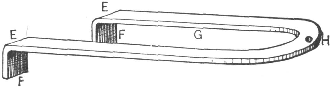
Fig. 71—The Anchor Plate
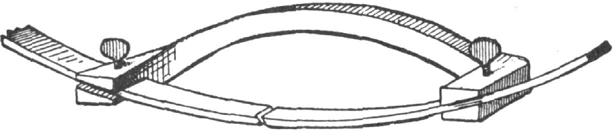
Fig. 72—Showing the Arrangement of the Truss
Device for Holding Tire While Welding.
When welding tire I have bothered me to keep their ends together, as I employ no helper. The little device which I have represented by Fig. 73 is the result of my study of how to accomplish the desired result most easily. For my own use I made the tool about twelve inches long, and used half-inch square Norway iron. I cut the bar off twenty inches in length, upset the ends, and then split them open about one and one-half inches. By this means the two jaws were provided. I made the splits about three-eighths or half an inch wide, so as to adapt them to receiving ordinary light tire. I drilled a hole in the center of the top of each jaw, cut a thread and put in a thumb screw. I made the bends three inches from the ends, and gave the jaws the requisite twist to suit the tool to the circle of the wheel. In use I put the tool first to the tire on the side toward the chimney, which keeps it out of the way of the hammer when the tire is put upon the anvil. The arch in the body of the device keeps it out of the way of the fire in heating. It is very satisfactory. I can put on my welding compound and feel perfectly sure of producing the weld just as wanted. I have seen many smiths bothered in welding tire, and think that my device will not be without interest to your readers.—By D. P.
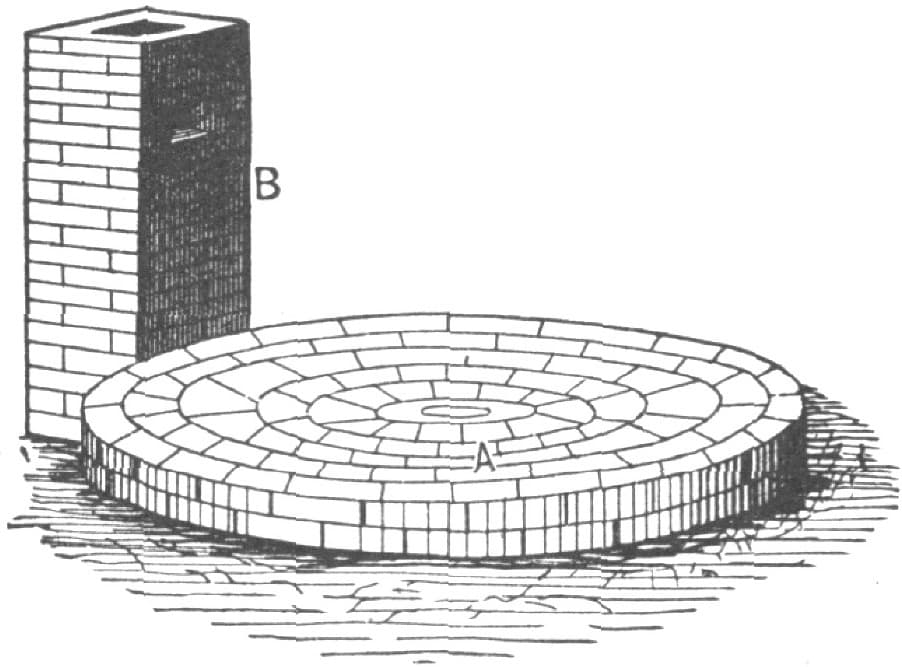
Fig. 73—“D. P.’s” Device for Holding Together Tire Ends While Welding
Tire-Heating Furnaces.
In setting tires in large shops we proceed as follows. We bring forty sets of wheels in the smith shop, where we have four smiths welding tires. Each of these smiths is supplied with a piece of chalk of a color different from that used by his fellow workers, and each man makes a chalk mark on the end of the hub of the wheel he takes in hand. After he has welded his tire his helper takes the wheel and tire to the furnace. By the time helper No. 1 gets his first tire at the furnace, in come helpers Nos. 2, 3 and 4; so you see there are four tires at the furnace at about the same time. Then we have a man at the furnace whose place it is to heat these tires and keep the furnace going and put the tires on. This gives the furnace a start with four tires. The furnace man puts them in the furnace and places his wheels outside the same, and this he keeps up all day. By the time he has seven or eight tires in the furnace, his first tire is warm enough. He takes it out and pulls it on the wheel; as soon as he has done this, he places it aside, sets another wheel on the tire plate and puts on another tire. By this time there will be four or five more tires ready to be heated, and as he takes a tire from the furnace he places another in. After these tires have been put on by the man at the furnace and are beginning to cool off in the air (for we never heat them so they will burn the felloes), another man takes the wheel and with a wooden mallet raps the tire lightly all around so as to have it down on the rim solid. He also faces the tire with the rim, and when he gets through he stands the wheels in sets. Then the inspector comes and examines every wheel, looking after the weld, dish, joints, etc.; also at the chalk mark of each wheel.
Now if we would allow each man to heat his own tire and put it on the wheels it would require twice as many smiths to weld as it does now, and we would have to pay eight smiths and eight helpers, instead of four smiths and six helpers, as at present, and in place of running five fires we would have to run eight, and these eight would cost (if they heated the tire the old way) three times as much more for coal, and twice as much more for shop room, with no more work turned out. In large shops the heating device pays; in small shops the old way of heating on the forge is cheaper; but let me tell you that you cannot heat a tire as it should be heated (uniformly) on the forge, but you can do this on a furnace.
Where you have from ten to twenty sets of tires to set per day it will pay to put in a furnace.—By H. R. H.
A Tire-Heating Furnace.
There are various styles of tire heaters used in different sections of the country. Some of these are for indoor work only, and others are for outdoor uses. The first step toward building an outdoor furnace, such as is shown by Fig. 74, would be to excavate a circle eight feet in diameter, and about two feet deep, and build or fill in with a stone and cement wall to within six inches of the surface.
On top of the stone foundation lay a bed of sand cement and fine mortar well mixed, and sweep it off so that it is horizontal, excepting a small incline to the center. On this bed lay the bricks in fine mortar, two courses. If the “row-lock fire-brick” shown in Fig. 75 of the accompanying illustration can be obtained, they are preferable to any other material. With “row-lock” brick begin at the outside and lay on one course, anchoring and tying them in at proper intervals, and when this has been done place around the whole two spring bands of one and one-half by one and one-fourth inches, secured with a half-inch bolt, or use a single band four by one-half and two securing bolts. This should be done while the mortar is green, so that it can be set up firmly all through. The top must be first cleared off and then covered with a thin slush of fine mortar, which will fill in all cavities. The chimney is built as shown at B in Fig. 74, the part A being the tire bed. The chimney should be at the base of a twelve-inch wall, and batten up to four inches, with an eight-inch or twelve-inch flue. At two feet above the tire bed there should be an eight-inch opening in the chimney, which will be alluded to again presently. The next thing to be done is to make the oven. In doing this, sheet-iron of ordinary grade, number twelve or number fourteen, thirty inches wide, is used. With it is formed a circle two inches or four inches less in diameter than the hearth. Fig. 76 illustrates the construction of this and other parts. D is a smoke hole to suit the hole in the smoke-stack. The top is furnished with a strong ring or eye bolt, and a hinged lid taking up about one-third of the diameter. I rivet all together with one-fourth inch rivets, and put in two good braces on the under side to strengthen the cover and to prevent its buckling or bulging, and at the bottom of A, Fig. 75 on the outside, it is necessary to rivet all the way around a plate of one by one-fourth. On the opposite side I place a vertical sliding door, with spring attachment to hold it in any position that will insure a draught.

A Tire-Heating Furnace as Made by “Iron Doctor.” Fig. 74—Showing the Chimney and Tire Bed
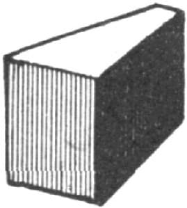
Fig. 75—The Row-lock Fire-brick
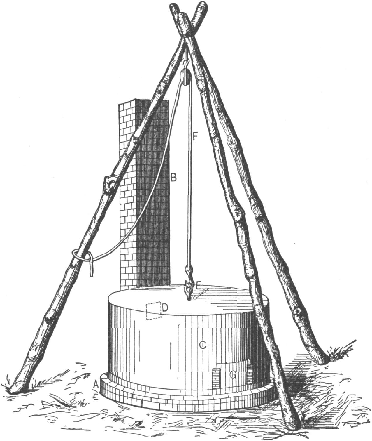
Fig. 76—Showing the Furnace Completed
The next thing to be attended to is the method of lifting this oven off and on for the removal of the tires. This is shown in Fig. 76. I make the tripod of three saplings, securing them at the top by passing a bolt through them, and from the bolt suspend the pulley block, through which passes the wire rope or chain fall FF hooked into the eye in the top E. C is the oven and G the door. This completes the whole. Place the tires in position on the hearth, first raising the oven; then place the fuel, lower the oven, open the door, and start the fire. As the tire becomes warm enough for setting, raise the oven and remove a tire and lower the oven. The whole operation does not require more than half a minute. While one tire is being set, the others are being heated, and no heat is lost.
This device is economical in operation, and besides lessens the cost of insurance. If the draught is too strong, a common damper may be put in the smoke-stack. The apparatus would work well with wood or charcoal, and by putting in grate bars, anthracite coal could be utilized at small expense. The heater, if often used, ought to be re-coated with fine mortar slush three or four times a year. To prevent rusting the iron work should be covered with coal tar several times a year.—By IRON DOCTOR.
A Tire-Heating Furnace.
I build a tire-heating furnace as follows: Fig. 77 shows the number of courses of brick used, fire brick for the inside court. A brick, I believe, is generally 9 × 41/2 × 21/2 inches; perhaps a little allowance should be made from these figures for mortar. The walls are two bricks of nine inches thick. The furnace being built to the square should have some old tire iron laid across it to hold up the bricks to cover the top inside, leaving an opening of about five or six inches at each end (see C and D, Fig. 78). The object of this is to cause the flame to spread instead of going straight up the chimney. The grate or bars may be for wood or coal. I use for fuel the chips, old felloes, etc., that would otherwise be in my way. I throw a lot of fuel in the furnace, place the fires on the bars BB, put fire to the fuel, and attend to other work while the tires heat. Sometimes we turn the tires, as they heat the fastest at the bottom, but this is not always needed unless they are extra heavy.

A Tire-Heating Furnace. Fig. 77—The Base
The capacity of this furnace is for common two-horse wagons, for two sets of tire, or eight tires, but we can keep setting tires all day by adding fuel and tires, as it does not take much fuel after the first heat.
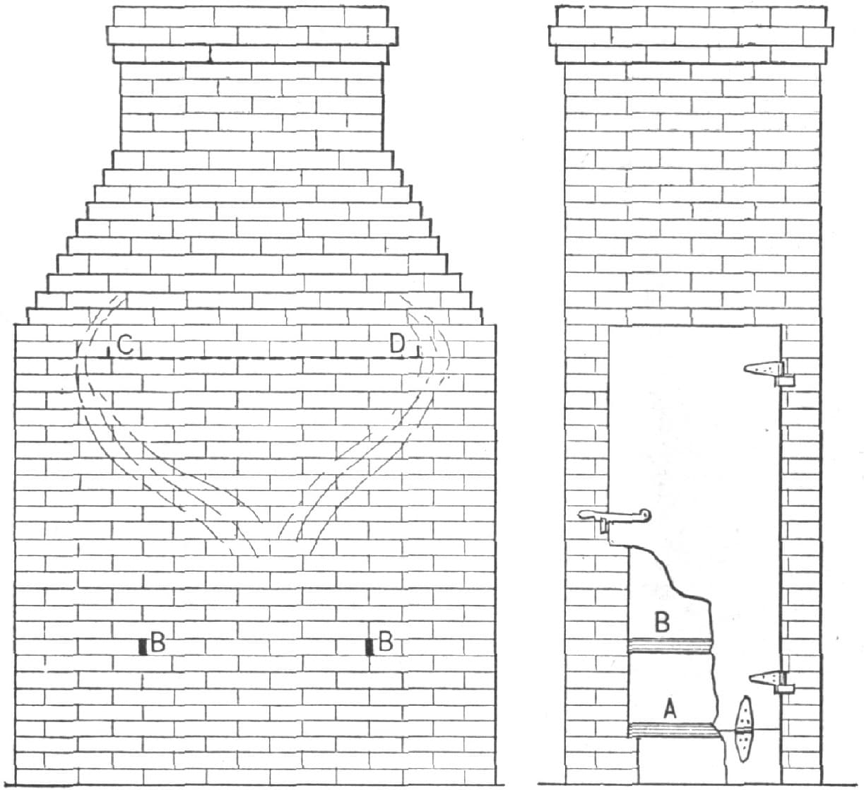
Fig. 78—Side and Front Views of the Furnace

Improved Tire-Heating Furnace. Fig. 79—Sectional View
It operates very well, it enables you to get at the tire easily when it is hot, it occupies but little room, will not endanger property by the fire used, and enables you to set tires at any time without being inconvenienced by wind or mud.
Allow me to say, also, that I do not put tires on wheels unless they are hot enough to expand and drop on without injuring the wheels, as I have seen wheels badly injured by trying to put tires on when they were too cold.
In the illustrations, A, in Fig. 78, represents the grate or bars, which are about six inches from ground, and BB, in Fig. 77, represent two heavy bars of iron to hold up tires twelve inches above the fire bars or grate. The door is sheet iron one-eighth of an inch thick and extends over the brickwork about one inch, with six inches cut off the bottom, and is secured with hinges to regulate the draft or inlet of air. The grate should not be within one foot of the door or the other end. If the fire is too close to the door it will warp it so that it will not fit the brickwork good. I use an ordinary latch to keep the door closed and ordinary hinges are bolted to the brickwork and door. The inside course of brick should be built rather wide up to the grate, to rest the latter on it.

Fig. 80—Front View
Fig. 77 represents the base. Fig. 78 includes side and front views. The stem of the chimney need not be thicker than one brick.—By T. GRIFFITH.
Improved Tire-Heating Furnace.
We present herewith two engravings representing an improved tire-heating furnace used by a large carriage company. Fig. 79 is a sectional view, in which the various parts are indicated by figures, as follows: One is the ash-pit, two the grate, three the tire-heating box, the size of which is fifty by fifty by thirty-six inches, and four is the flue.
Fig. 80 is a front view of the furnace. It will be observed that the pins from which the tires are suspended are arranged so that the front tires can hang inside of the rear ones. This furnace is capable of heating ninety sets of tires a day.
Making a Tire Cooler.
PLAN 1.
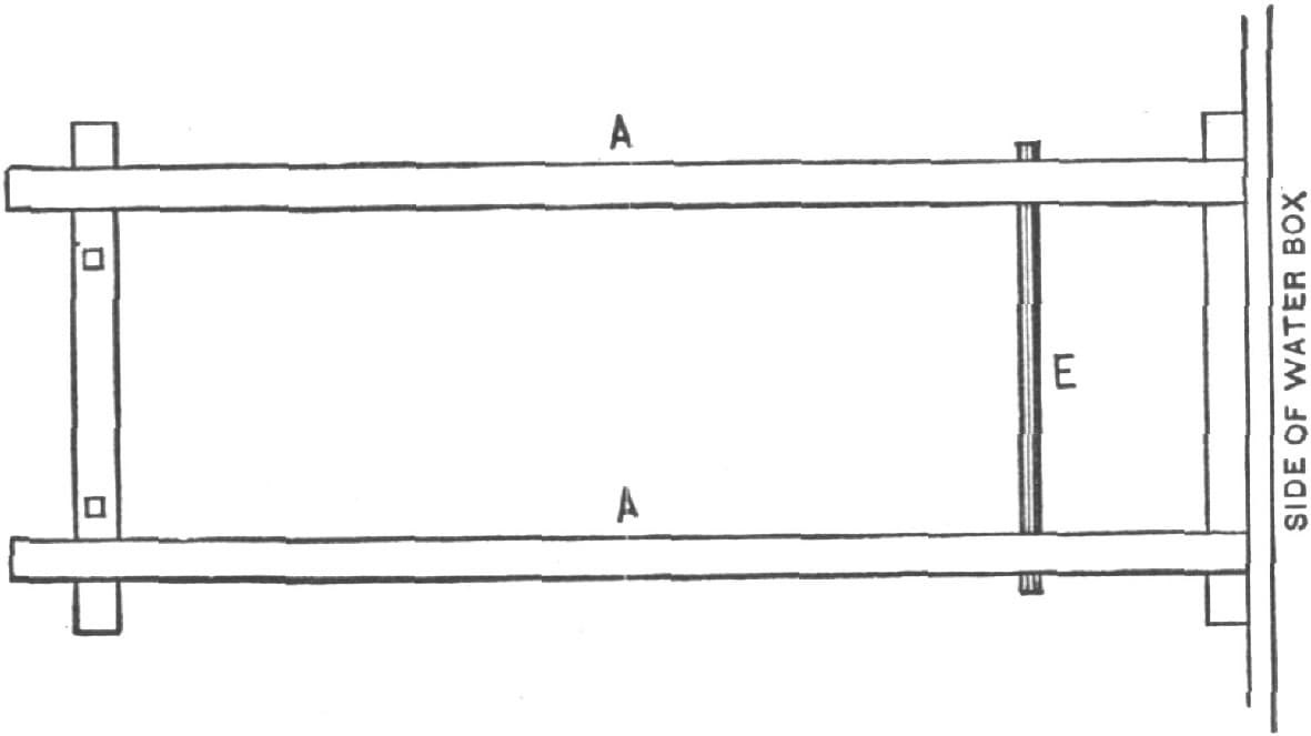
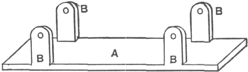
I make a tire-cooling frame as follows: A, in Fig. 81, is six feet long, and is made two by four or else three by three. It is nailed to the water box, the latter being sunk so that the top is two inches above ground. A is sloped to the ground at the back end. An iron spindle goes through the hub of the wheel and into the holes shown in B, Fig. 82, thus holding the wheel up in place while it is being cooled. B is of four by four timber. It works on the same shaft with C, Figs. 83 and 84, and the trigger D, Figs. 82 and 83, holds them together at the back end. The wagon wheel is placed on C. The spindle is passed through the hub and into the most suitable hole in B. The hot tire is then put on the wheel, and both C and D are raised together until they stand perpendicularly. The lower side (or edge) of the wheel goes in the water in the box. When the tire is cool enough to stick to the wheel, the trigger is raised and C falls back to its place, while B still stands up like a post. When the tire is cold and trued up, the iron pin is drawn out, the wheel is rolled to one side, B is turned back in its place and latched by the trigger D, and then another wheel is placed on the frame as before. Fig. 85 shows the complete apparatus.
Making a Tire Cooler by the Method of “J. A. R.” Fig. 81—Showing the Frame
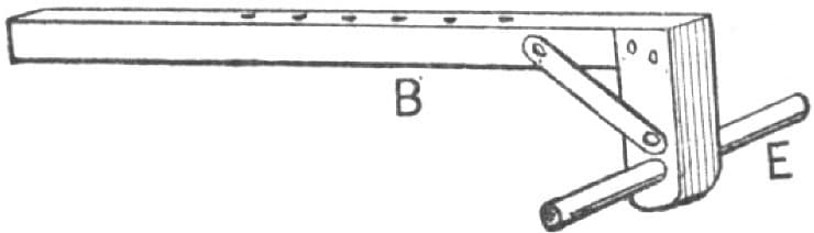
Fig. 82—Showing the Device for Holding the Wheel
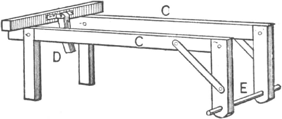
Fig. 83—Showing the Arrangement for Supporting the Wheel
The top beam of B is about six inches lower than the top beam of C, in order to give room for the end of the hub and allow the rim to lie back on C C. The latter are four feet long and eighteen inches high. The shaft on which they work is eighteen inches from the water-box.
There are, I believe, only two of these frames yet made. I made both of them, and have been using no other for cooling tires for six years. One man can cool tires better with this frame than any two men can in the old way.—By J. A. R.
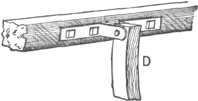
Fig. 84—The Trigger
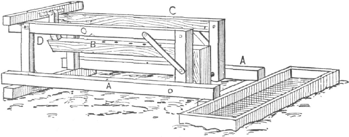
Fig. 85—Showing the Tire Cooler Completed
PLAN 2.
By using this tire cooler the smith will not be obliged to swallow smoke any more, and he will be in no danger of getting his eyes sore; he will never have a burnt felloe, and he can do his work in one-fourth the time usually required. It can be made at an expense of about twelve dollars, in the following way:
Make a box of one and one-eighth inch pine lumber, wide enough for the largest sizes of wheels, say five feet, and make it about ten inches longer than it is wide, and sixteen inches high. Put three pieces of scantling on the bottom crosswise, and extending out two or three inches.
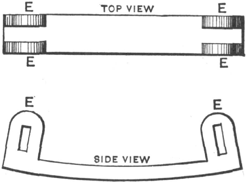
Take a set of wagon box straps and fasten them on the outside as you would on a wagon box. Get two pieces of one and one-fourth inch round iron, and bend them in the shape shown in Fig. 86. Weld two collars on each piece to hold the trestle in its place, and square one end of each to receive the crank shown in Fig. 87. This crank is made of tire iron. Make the connecting rod shown in Fig. 88 and the lever, Fig. 89. Cut a slot in the lever so that a bolt can be used to fasten it to the connecting rod. Then drill a hole in the elbow to fasten it to the box. Fig. 90 represents a piece that is used to go over the lever in the elbow to make it more solid. Fig. 91 is a hook used on the end of the box to hold the lever down while the tires are being put on. Fig. 92 represents one of four pieces used to fasten to the box the two pieces shown in Fig. 86. Make your trestle of iron or wood, and twelve inches shorter than the box. By lowering the trestles you will move them to the right side a distance corresponding to the bend in the piece shown in Fig. 86. This bend is eight inches. Raising the lever will draw the wheels into the water. Fig. 93 represents the trestle. Fig. 94 is a top view of the cooler, and Fig. 95 is a side view.—By C. M. S.
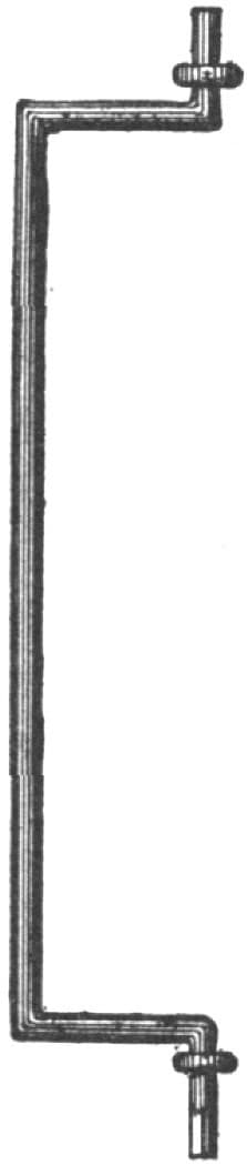
Fig. 86—Showing How the Iron is Bent
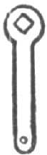
Fig. 87—Showing the Crank

Fig. 88—The Connecting Rod
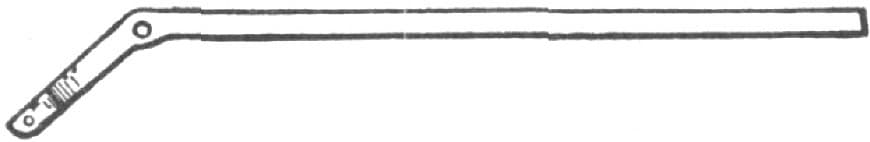
Fig. 89—The Lever
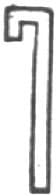
Fig. 90—The Piece that is Fitted on the Elbow of the Lever
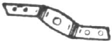
Fig. 91—The Hook
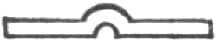
Fig. 92—The Piece Used in Fastening to the Box the Irons Shown in Fig. 86
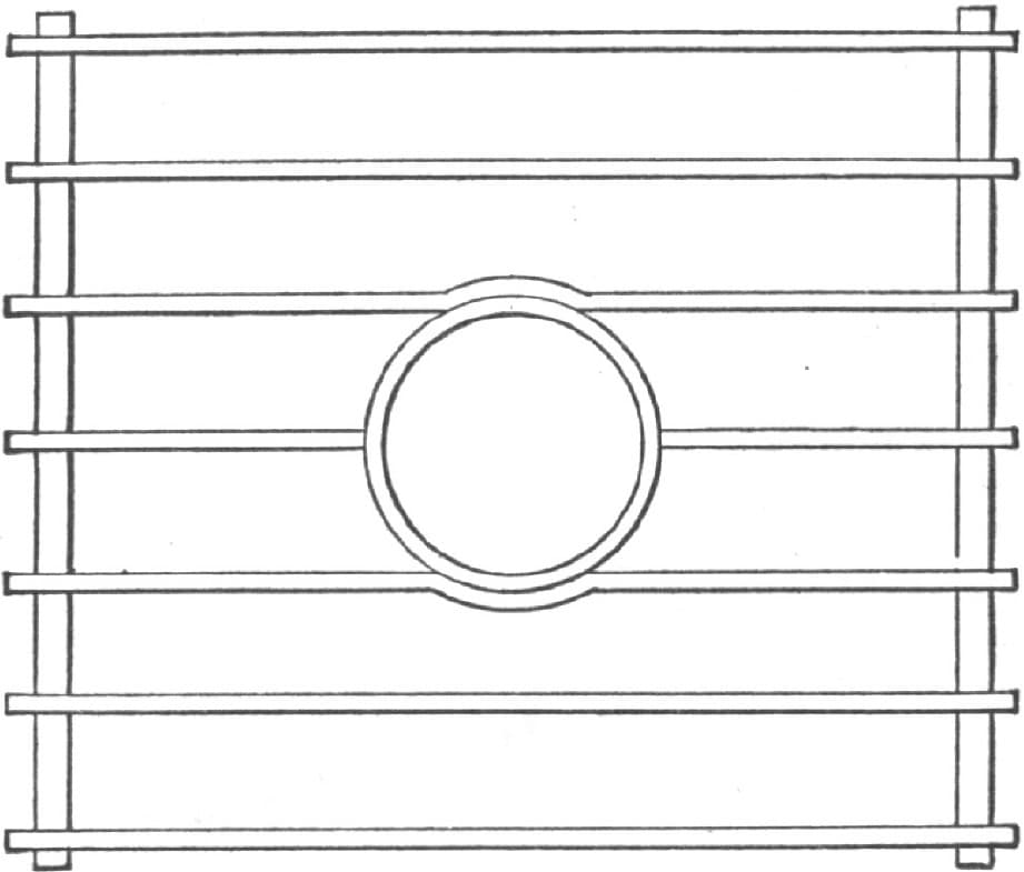
Fig. 93—The Trestle

Fig. 94—Top View of the Cooling Apparatus
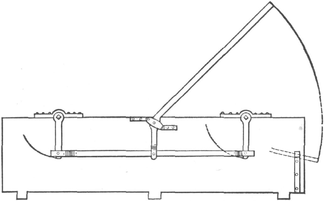
Fig. 95—Side View of the Cooler
Tire Shrinking.
In the South we have, as a general thing, very hot, dry Summers, and these, with sand and rocks, destroy wheels quickly. Now, I claim that there is no surer way to ruin wheels than to shrink the tires. Let’s see: You have your tire set when very dry if you want them to remain tight. So soon as you get in rain your wheels are dished out of shape. Now you have paid the smith to ruin your wheels. As a remedy for this, I recommend that you have your rims painted, and have it done in time. It is cheaper than shrinking, and preserves the wheel, while the other course destroys it. —By NICHOLSON.
Getting the Precise Measurement of a Tire.
To get the precise measurement of your tire, have it cold or at a normal temperature throughout when you measure it with your traveler.—By TIRE SETTER.
Shrinkage of Wheel Tires.
I wish to say a few words on tire setting. First, the edge of the tire wheel should be as thin as possible, as it makes a great difference in measuring. A man will not carry his hand so true as not to cross the face of the tire wheel as he runs around the wheel or tire; therefore the thinner the better.
Secondly, do not screw down any wheel that does not have loose spokes, not even those that dish the wrong way, as they can be made to dish the right way by simply planing off the tread on the back and not the front felloe, as that will leave it so the tire will bear hardest on the front, which will dish the wheels the right way. Sometimes it is necessary to cut out a piece of the felloe if it is very bad. To screw down a wheel to stop it from dishing is an injury to it, as it starts all the joints, and it will be looser after the screw is removed than it would be if it were set less tight and left to dish as it naturally would.
Thirdly, as there is a great difference in the shrinkage of tires, they should be measured cold. The draft depends wholly upon the ability of the wheel to stand it. Tires never need any fitting up with sledge and light hammer except at the welds, and that, if care be taken, need not be done. They should be left to cool of their own accord, and no water should be used, as that swells the wood; it does not require much heat to expand a tire. From two to three minutes is enough for light tires to heat in the forge, as they will not then burn the wood, and the wheel can be set up one side out of the way and another one put on the form. A man can do more work by this method than by the other, and it will be better for the wheel, as all the pounding occupies time and injures the wheel. I have never worked on heavy work; therefore I will say nothing about it.—By O. F. F.
Measuring for Tire.
For the benefit of blacksmiths who, perhaps, are setting tires in the old-fashioned way (i. e., by guess,) I will give full details of my method.
In taking the measure of a wheel and tire, it is necessary to get the exact measurement of both; therefore, the smaller the mark on your tire wheel the better. A common slate pencil makes the best.
Use a wooden platform to set all light-wheel tires.
Take a half-inch round rod, about two feet long, turn one end and weld it, leaving a loop or eye about three inches long by an inch and a half wide; cut a thread on the other end of the rod about six inches; make a hand wrench for this, with the handle about six inches long.
Fasten a piece of wood or iron (strong enough not to spring) through the center of the platform, and low enough not to strike the end of any wheel hub when the wheel lays on the form.
If the spokes are loose, or work in the hub or rim, it is because the rim is too large, and there should be a piece taken out of it (the amount to be taken out depending on how much the spokes have worked), varying from the thickness of a saw-blade to three-fourths of an inch.
A light wheel should have the rim left open in one joint (the others all to be tight), about one-sixteenth of an inch; start a small wedge in this joint to crowd all the other joints together. Take your tire wheel and place the notch on the end of the rim at the right side of the joint; measure around toward the right until you come to the joint where you started from; make a mark on the tire wheel, at the end of the rim, leaving out the width of the joint which is left open.
Place the notch of your wheel on a mark on the inside of the tire (standing inside the line), measuring around to the right, until the tire wheel has taken the same number of revolutions that it did on the wheel, cutting the tire off as much short of the mark on the tire wheel as you wish to give it draft.
Light tires should measure the same as the wheel while hot from the weld; heavy tires should have from one-eighth inch solid draft for medium to one-half inch for cart wheels: solid draft, i. e., after the joints of the wheel are drawn together solid.
On old wheels, the ends of the spokes often rest on the tire, the shoulder having worked into the rim, thus letting the spokes rest wholly on the tire; these should be cut off a little below the outside of the rim.
For light wheels, put the wheel on the platform face down; pass the rod through the hub, bore a hole in a piece of board to put over the end of the hub, running the rod through the hole; put on the wrench, and draw it down to where you wish the wheel to be after the tire is set; heat the tire on the forge, heating it all the way around; when you put it on the wheel, cool it enough so it will not burn the rim; fit it with a light hammer, holding a sledge on the inside of the rim, and strike lightly on the tire over each spoke as it is cooling.
If a wheel should be turned in toward the carriage, after cutting some out of the rim, put it on the platform, face side up; place a few pieces of board under the rim, draw it back through, and give the tire three-sixteenths solid draft for a light wheel; more draft for a heavy one. —By YANKEE BLACKSMITH.
Tire Shrinker.
NO. 1.
A tool by which any tire can be upset, that is usually taken off from wheels without cutting, is shown by Fig. 96. It is made of two by five-eighths inch tire iron, cut one foot long. The ears are made of the same material. The keys should be constructed of good spring steel. To upset a tire, first heat it and bend a small portion inwards, then put the tire in the clamp and drive home the keys and flatten down the bent part with the hammer.—By R. E.
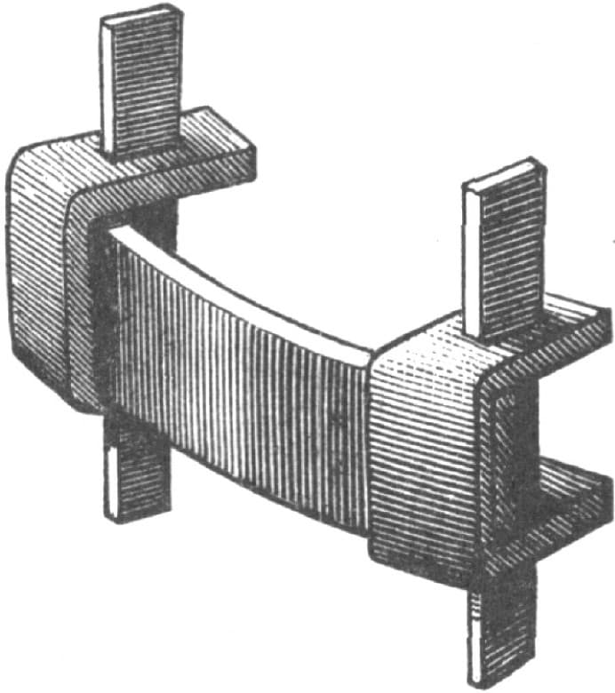
Fig. 96—Tire Shrinker, Contributed by “R. E.”
Tire Shrinker.
NO. 2.
A tire shrinker, which I have invented and which almost any blacksmith can with care build for his own use, is represented by Fig. 97. A and B are sliding bars, made of five-eighths by one and one-half inch iron. They are so arranged that when the handle of the tool is depressed they slide in opposite directions. D and C are cross bars, with lips turned up for holding the edge of the tire. They are faced with steel upon the inside, and are notched and hardened the same as the dogs K, which work in front of them. D is welded solid to B, and C is welded to A. Both D and C are provided with a number of holes, threaded for the reception of the set screws which hold the dogs in place, and so distributed as to permit of moving the dogs backward or forward as the width of the tire may require. The two slides A and B are held in place by suitable straps which pass over them, and which are bolted to the bench. The face of the bench is protected by a thin plate of metal placed under the sliding bars. The bars are moved by connecting rods fastened to studs welded to opposite sides of the shaft to which the handle is attached. These studs are about two inches in length. On moving the handle one of the connecting rods pushes and the other pulls. They are connected with the eyes on A and B by half-inch bolts. Snug fits are necessary. The shaft should be made as short as the dimension of other parts of the tool will permit. It should be square in section at the part where the handle is joined to it. It is bolted to the bench by the end pieces shown in the cut, provided for the purpose. The dogs K K are operated by a short lever handle so arranged that tires may be easily managed by a single hand. A shrinker properly constructed to the design here described will shrink the heaviest tire three-quarters of an inch at a heat.—By R. H. W.
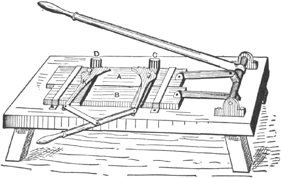
Fig. 97—Tire Shrinker in Use by “R. H. W.”
The Allowance for Contraction in Bending Tires.
Templeton’s rule for contraction is as follows: The just allowance for contraction in bending (on the flat) is to add the exact thickness of the metal to the diameter—e. g., in the case supposed the circumference is three feet and the iron one-half inch. The diameter would be eleven and one-half inches, add half an inch for thickness of tire, giving one foot diameter, or three feet one and five-eighths inches in circumference.
In bending on the edge, ring instead of hoop shape, add the breadth instead of the thickness of the metal to the diameter. Of course there is no allowance here for welding. —By WILL TOD.
Setting Tire—The Dishing of Wheels.
My rule for setting tire is to first see that the rim on new wheels or old is wedged down tight on the spoke, then I clip the spokes one-sixteenth of an inch below the tread of the felloe. I saw the felloe joint open from one-eighth to one-quarter of an inch, according to the size of the wheel. I then drive a wedge in the open joint so as to be sure to close all of the other joints tightly, then I measure the wheel and always get the right length. I next place my wheel on the wheel bench. When the wheel is placed over the rod I place a block on the end of the hub, put the tail tap on and screw it down. If it is a light patent wheel I screw all the dish out of it, that is, make it so that the spokes are on a straight line. I make the tire the same size as the wheel when it is to have a red-heat as for light wheels. For new heavy wheels, such as those used on job or road wagons, I allow an eighth of an inch for draw when the tire is red-hot. If a set of wheels is badly dished they can be screwed down to the back side of the wheel. Keep the screw there until the tire is cold, and when the wheel is released it will dish again, but not so much as it did before. If the spokes are sprung leave the wheel on the bench as long as you can.
I heat all my tires, except those for wagons, in the forge. I seldom heat tires hot enough to burn or even scorch the felloes. In my opinion there is no necessity for burning rims. I clip the ends of the spokes because in old wheels they are too long and will not allow the tire to rest evenly on the rim.
When the spokes are too long the wheel will be dished, because the tire presses on the ends of the spokes instead of on the rim, and the wheel will be rim-bound besides. It is better for the spokes to be an eighth of an inch short than to have them go through the rim. When the spokes are a little short the tire will press the rim down on the shoulders of the spokes.—By W. O. R.
About Tires.
The question as to what is the best kind of tire to use is an interesting one. My idea is that the kinds of tire should vary with the localities and conditions in which they are used. If the vehicle is to be used in a city and on street railway tracks, a round-edge steel tire is best. It will throw lots of mud, but it will preserve the felloes.
On sandy roads a bevel-edge iron tire would be preferable, because the wear is all in the center and is caused by the sand coursing down the tire when in motion. On earth roads the square-edge iron tire is the best. If over paved streets or macadam roads, the square-edge steel tire (crucible mild) is by far the best. Its wearing capacity cannot be questioned, and another thing in its favor is that it will not throw mud and dirt over vehicle and occupants. In fact, my experience has taught me that for general purposes the flat-bottom, square-edge tire overtops all others for wear and general utility.—By J. ORR.
Setting Tires.
There is no need of riveting. Bend your tire (upset if you like—I don’t) so that the ends come properly together, set it in the fire, heat, chamfer both ends with one heat, and set it back for the welding heat. If it is inclined to slip, take a pair of tongs and give it a pinch. It will stay, you bet. If it is a light tire I split the ends and lock them as we lock spring leaves for welding, except that I split once instead of twice.—By R. H. C.
Putting on a New Tire.
I put on a new tire in a way different from some other smiths. My plan is as follows: I first see that my tire is perfectly straight and then lay it on a level floor and run the wheel over it, commencing at a certain point and stopping at the same point. I then allow three times the thickness of the tire to take up in the bend, and allow one-quarter of an inch for waste. I cut the tire off, put one end in the fire, heat, and upset well, chamfer and punch, then turn the other end and give it the same treatment. I am careful to upset well. I then put it through the bender, rivet and weld. This is, I think, the easiest way of doing the job, and it can all be done by one man if the tire is not too heavy.—By JERSEY BLACKSMITH.
Tiring Wheels.
There is much time wasted, at least in country shops, in the method in vogue of welding tires, viz.: scarfing before bending and pinning.
A much quicker and easier way is to cut the bar the right length, bend the end cold, to allow it to enter the bender, and bend; then track your wheel, if you have not already done so, and then your tire. If you have made a good calculation when you cut your bar you may not have to cut again, but if there is any more stock than you wish for your weld, before scarfing trim off with the fuller if the tire is heavy, or with the hand hammer if light. Then lap according to your own judgment and take a good slow heat and weld.
In measuring the wheel, if there is much open joint insert a wedge sufficient to press all the joints together but one, and start your truck from one end of the rim and run to the other. Thus you get the exact size of the rim: and when you truck your tire, mark the size of the rim on it, and add the amount of stock you wish for the weld, less the draft you want to give, and if there is any over cut it off.
By this method of measuring, as you will readily see, there is only one calculation to make, viz.: the amount of stake required for the weld.
Some object to this way of welding because it leaves a “slack” place each side of the weld, but if you are careful about lapping and heat slowly in a good fire you will not have any trouble.
I do not think it is any benefit to pin even a light steel tire. If it is bent true and scarfed short it will not slip unless roughly handled. If tires are too large or stiff to bend cold, I heat scarf and bend one end before putting in the bender.
In resetting old tires measure both the wheel and tire before heating, then you can see how much it wants to upset and can do it in one heat if it is not very loose. I use the Green River upsetter and can recommend it; it will upset from three-sixteenths to 4 × 7/8 or 3 × 1.
If you have any joint sawed out of the rim, upset the tire on the same side that you saw and the bolts will come very near the same holes.—By A CAPE ANN BOY.
Setting Tires in a Small Shop.
I have a small shop, only 20 × 30 feet, and not much room to spare in it. So it is likely that my way of setting tires with the space I have at command is worth describing. I have a box twelve inches square inside, ten inches deep, and with a top that is two inches below the level of the floor. The lid is made of inch boards, doubled and riveted together, with a ring in the middle, so that when I want to set a tire I can take up this top, put the hub in the box and let the rim rest on the floor, and thus secure a solid place to set the tire. When the job is finished I replace the lid and have a level floor again, and heat all my tires on the forge and cool in the tub.—By A. T. P.
Resetting Light Tires.
For the benefit of the craft I will give my way of resetting light tires (I mean those that are bolted on). In the Summer time tires are apt to become loose, and the wheel will not wear well when this is the case.
I take out the bolts, mark the tire and felloe, and drive the felloe from under the tire till it falls off. I then get some press paper, such as is used in woolen mills, cut it in strips the width of the felloe, and tack it on with small tacks till the wheel and tire measure the same in circumference, or till the wheel is a trifle the largest. I then heat the tire to a black heat, drop it on and let it cool off. If it burns I sprinkle it with a little water. I put the bolts in the old holes. I never make new ones. This job can be done very nicely, and the result is much better than if the tire was cut and welded or upset. The paper I use is hard and about one-thirty-second of an inch thick.—By G. W. B.
A Handy Tire Upsetter.
I have a little tire upsetter that I find handy. It is made as follows: Take a piece of iron three-eighths or one-half inch thick and ten inches long and weld on the ears E shown in Fig. 98. In these ears drill holes and cut them one into the other to form slots or keyways. Then take a piece of spring steel and draw it out and make a taper key of each slot. Then put a kink in the tire, lay the upsetter and keys on the anvil all ready, beat the tire where the kink is, and quickly key it on the upsetter as shown in Fig. 99, and by hammering down the kink the tire is upset.—By A. L. D.
A Handy Tire Upsetter, as Made by “A. L. D.” Fig. 98—Showing Top and Side Views of the Device
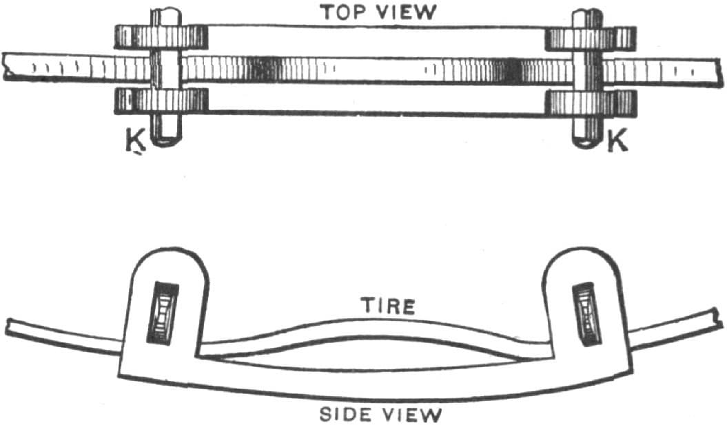
Fig. 99—Showing the Upsetter Applied to the Tire
A Good Way to Upset Light Tires.
An excellent plan for upsetting light tires well and cheaply is as follows: First make a short curve in the tire by placing it on the horn of the anvil and striking on each side. Then place the tire smooth side up over an old rasp, and let the helper grasp the tire and rasp it close to the curve, using a heavy pair of tongs. You do the same on the other side of the curve. Then while it is still hot strike it lightly and quickly with a small hammer.
I have found this plan to work especially well on light buggy tires.—By G. W. P.
Tire Clamps.
A tire clamp is a little appliance which every jobbing wagon-maker ought to always keep on hand, and which every wagoner traveling any distance ought to carry with him. It is an appliance for securing a broken tire when time or place will not permit rewelding or resetting it. The manner of making the clamp is shown by Fig. 100, which is a flat piece of iron about one and one-quarter by twelve inches. Each of the ears, B, B, B, B, has in it a hole for the insertion of a bolt or clinch pin. A rests on the tire and the ears extending over the felloe or rim. Fig. 101 shows another style of clamp, C denotes the plate and D, D, D, D, are clips with threaded ends. Fig. 102 is the clip yoke. Fig. 103 is a simple band E, which fits the tire. F, F are provided with ears, for bolts or clinch nails. These styles of clamps are easily made, and in making them ordinary iron may be used.—By IRON DOCTOR.
Tire Clamps. Fig. 100—Showing One Style of Clamp
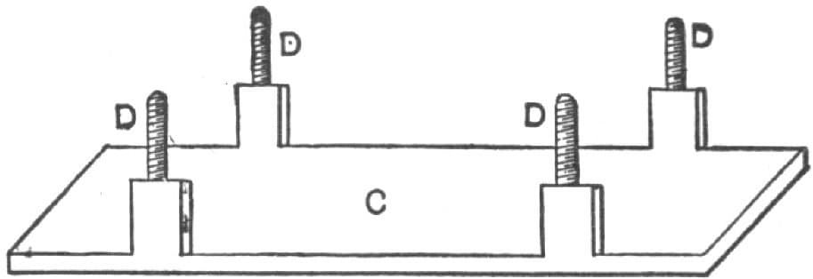
Fig. 101—Another Style of Clamp
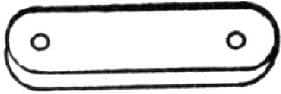
Fig. 102—The Clip Yoke
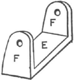
Fig. 103—Another Form of Clamp
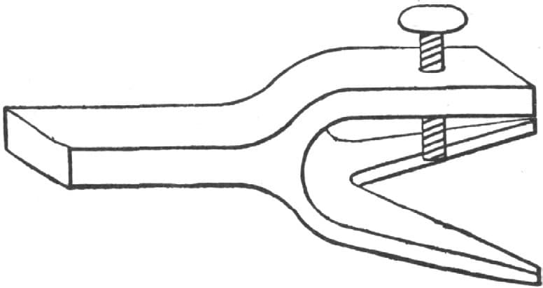
A Tool for Holding Tire and Carriage Bolts.
A tool which I have used about ten years for holding tire and carriage bolts is shown by Fig. 104. I put steel in the point of the screw, and finish it up like a center-punch. The screw is five inches long, with a handle three inches long.—By C. H.
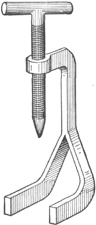
Fig. 104—A Tool Made by “C. H.” for Holding Tire and Carriage Bolts
Device for Holding Tire Bolts.
I inclose you a sketch of a tool we made some time since in our shop, which we are using with very satisfactory results. It is for holding tire bolts in old wagon wheels to prevent them turning round when it is necessary to screw up the nut. It is needed in every shop. Such a tool is made as follows: A piece of steel one and one-half inches by three-eighths of an inch, is split at one end into three parts, each about four inches in length. A hole is tapped in one of them for a set screw, and the forks are then bent into the shape shown by Fig. 105. The manner of using the tool is shown in Fig. 106. It is placed upon the wheel with the point of the set screw against the head of the bolt. When the screw is drawn up tight it never fails to hold the bolt from turning.—By APPRENTICE.
“Apprentice’s” Device for Holding Tire-Bolts. Fig. 105—General View of the Tool
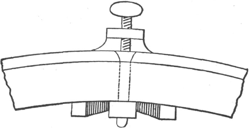
Fig. 106—Manner of Applying the Tool
Tire Jack.
A device for setting wagon tires which I find extremely useful, one which I have employed for fifteen years past, is shown by Fig. 107. In length the tool is thirty inches, and is made of tough, hard wood. The principal piece B is four inches wide at the curved part, which fits over the hub at C, and in the first fifteen inches of its length tapers down to three inches. The other half is three inches in width throughout. The slot is one inch in width. In thickness this piece is one and one-half inches. It is provided with five-sixteenths inch pin holes at different points, adapting it to use upon different sized wheels. The lever is twenty-four inches long, and is of convenient size for grasping in the hand. The face of the part which comes against the tire is provided with an iron plate, thus protecting the wood from burning. The wheel is laid flat upon the floor, with one part of the hub in a hole provided to receive it. The tire is placed in position. Then to draw it into place this device is braced against the hub at C, and the iron-shod end of the lever is brought against the tire, as shown at A, when, with a very small exertion, the work is completed.—By W. A. E.

Fig. 107—“W. A. E.’s” Tire Jack
A Tool for Holding Tire Bolts.
A tool for holding tire bolts I make as follows:
Take a piece of round iron about fifteen inches long, make a hook at one end, and about three and one-half inches from the hook weld on the iron a chisel-pointed piece of steel which is intended to rest on the bolt-head. By pressing on the other end of the iron you form a clasp which works much easier and quicker than a screw. Fig. 108 represents the tool and the method of using it.—By J. A. H.
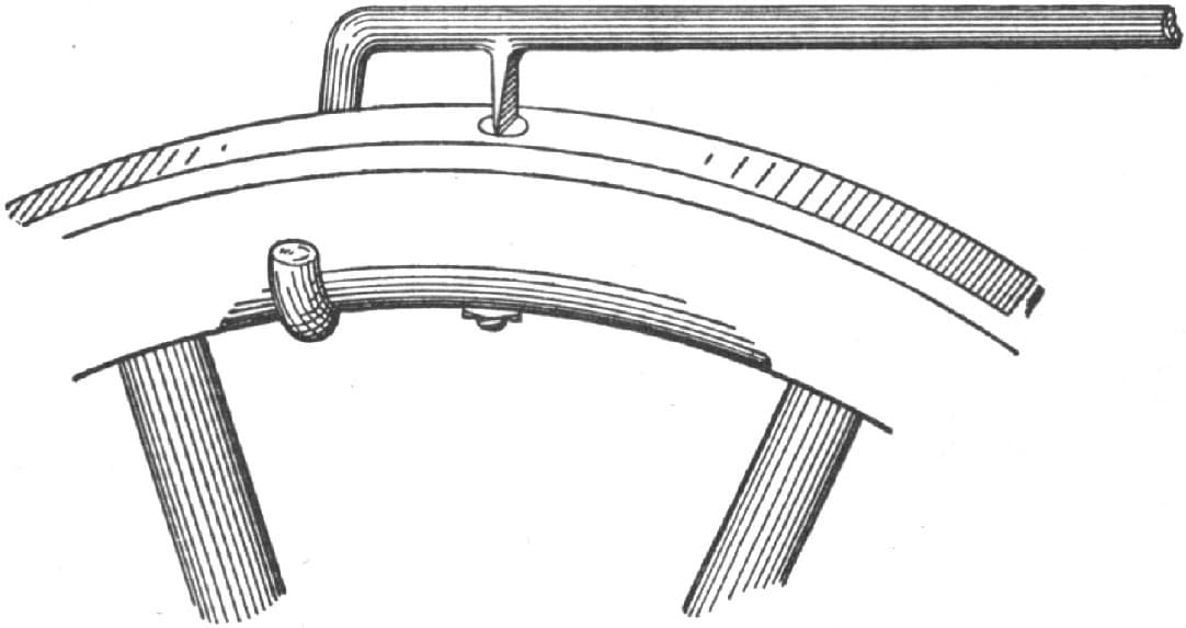
Fig. 108—“J. A. H.’s” Tool for Holding Tire Bolts
A Device for Holding Tire Bolts.
To hold tire bolts while removing the nuts, a better way than putting the wheel in a vise is to take a piece of three-quarter inch sleigh shoe steel, about fifteen inches long, and weld on one end of it, at right angles, a piece of seven-sixteenths inch round iron, long enough to work onto the rim nicely. Have the edge of the steel about three-fourths of an inch from the face of the tire, then screw or weld onto the edge of the steel, about two inches from the hook, a piece with a burred end, Fig. 113. This tool is a lever which can be used with either hand and will hold a bolt till the nut starts.—By E. M. C.
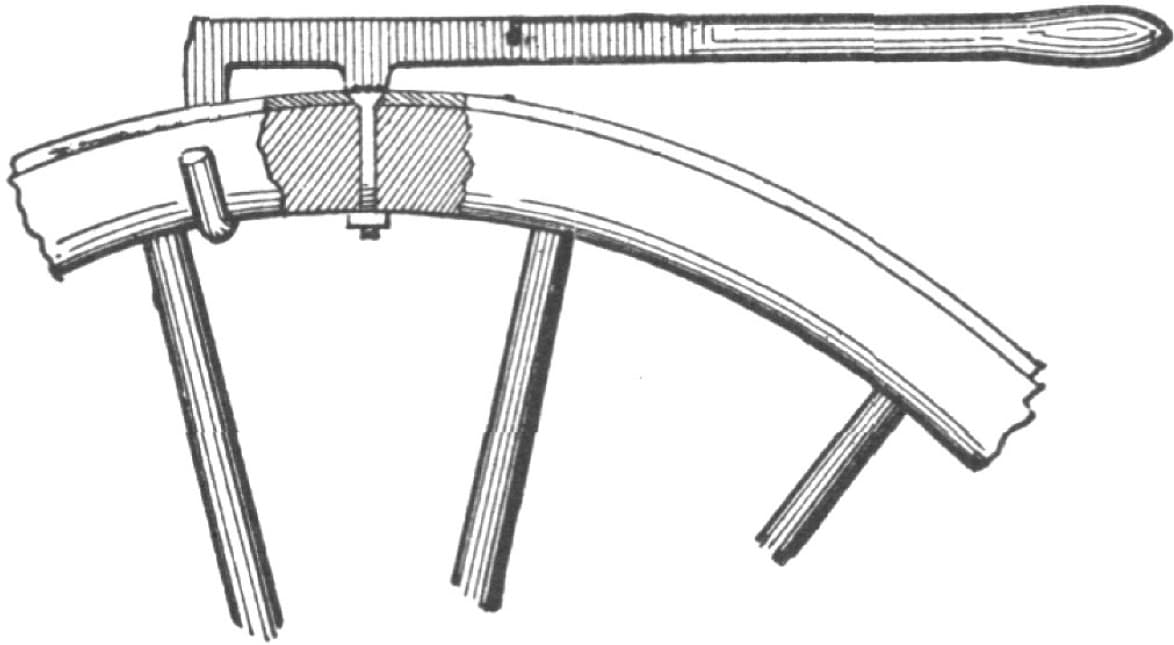
Fig. 109—A Device for Holding Tire Bolts
Enlarging a Tire on a Wheel.
To enlarge a tire on a wheel which is too tight, drive the felloe out so that a little more than half of the face of the tire shows for a few inches in length of the tire. Take a small fuller and a hand hammer, set the tire on the anvil, draw one edge of the tire, drive it through to the other side and draw the other edge, but do not draw too much or your tire will be loose. —By C. W. BRIGDEN.
A Tool for Setting Tire.
A tool for drawing tire on wheels, in setting tire, is shown by Fig. 109. A glance at the sketch will show its construction. From the rivet to C or A the distance is three inches. The jaw is hooked to suit, as shown in the illustration. When using the tool slip the lip under the felloe, with the shoulder against the rim, fetch the hook over the tire, bear down and squeeze the handles together at the same time. The handles are two feet long and five-eighths of an inch round. Make the shoulder in the jaw so that it will come inside the hook when the jaws are closed.—By JAKE.
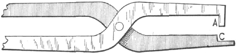
Fig. 110—A Tool for Setting Tire
Putting a Piece in a Tire.
A smith is often compelled to weld a piece in a tire, and to weld three or four inches in a tire is no easy job if done by one man alone. I do it as follows:
I cut a piece of iron of the same size as the tire and about twelve inches long. I open the tire about ten inches and lay the short piece on the tire or under, as at A, Fig. 111. I fasten the two ends together at A with an iron clamp, weld the piece to the tire at B B, then lay the tire down, take a traveling wheel beginning at C and when I come around cut off what I need. Or I start the traveling wheel at the end of the short piece A and cut out of the tire as much as necessary. By this latter plan I avoid getting the two welds too close together.—By E. K. WEHRY.

Fig. 111—Putting a Piece in a Tire, as Done by E. K. Wehry
A Tool for Drawing on Heavy Tires.
A very simple tool for drawing on heavy tires, and one which experience will tell any man how heavy to make, is shown by Fig. 112. The part marked b is the hook, which is split so as to straddle the main lever. To use the tool throw the hook over the tire, place the shoulder a against the felloe and bear down. I use this tool for setting all kinds of tires from one and one-half to four inches wide, and like it better than any other I have ever seen.—By S. E. H.
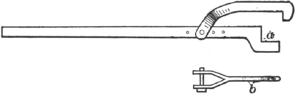
Fig. 112—Tool Made by “S. E. H.” for Drawing on Heavy Tires
Welding Heavy Tires—A Hook for Pulling on Tires.
I will describe my way of welding heavy tires. I do not scarf the ends at all. I cut off to the length desired and bend it as round as possible, put one end on top of the other, take a good clean heat and drive it right down with the hammer. This leaves the tire as heavy at the weld as at any other part and it will never break.
Fig. 113 represents a hook I use to pull on tires. It answers for all widths. The hook is loose. The way of making it is shown plainly enough in the cut.—By A. B.
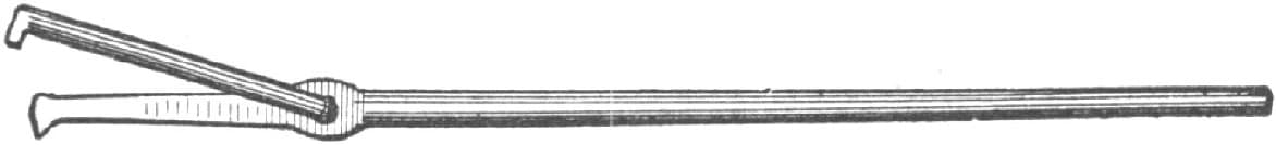
Fig. 113—A Hook Made by “A. B.” for Pulling on Tires
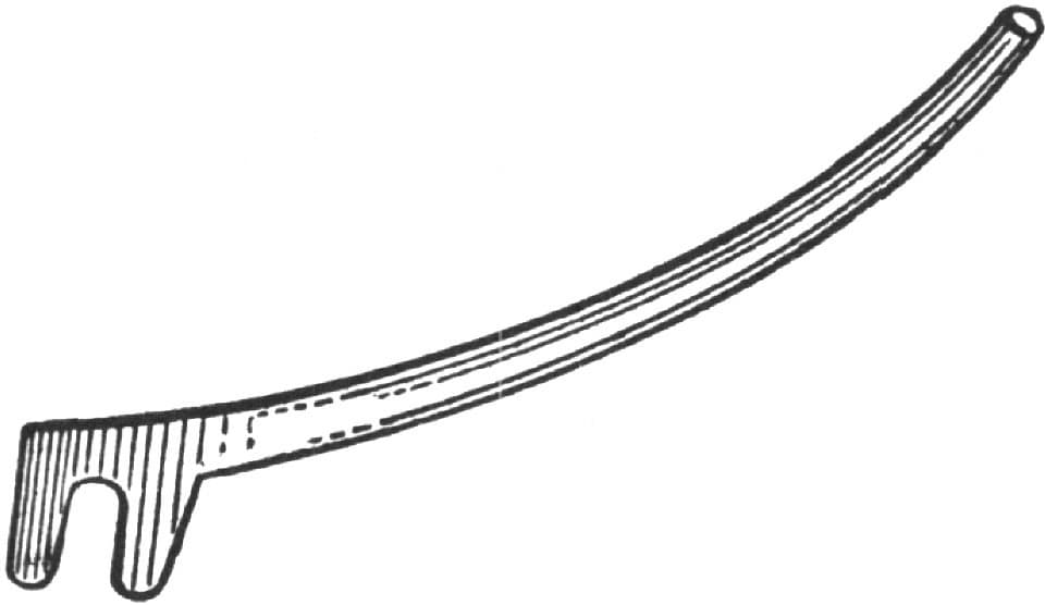
A Handy Tire Hook.
Herewith will be found an illustration of a tire hook, Fig. 114, which I use for buggy tires. It is made of an old spring two inches wide and one foot long. For tires larger than those used on buggies the hook is made larger in proportion. The brace B is one and one-half inches from the dotted line at the point. The point H is three-fourths of an inch long. The hole in the handle is used to hang the tool up.—By E. W. J.

Fig. 114—“E. W. J.’s” Handy Tire Hook
Putting Tires on Cart Wheels.
I think some of the craft would like to know a good method of putting tires on cart wheels. Say four inches wide, half an inch thick, and sometimes five inches by five-eighths, which is a very hard tire to weld if you don’t know how to go to work in the right way. I begin by placing the tire on the floor and then roll my wheel, starting at one of the joints and stopping when I come to the joint again. I then cut it off, first making an allowance of two or three inches. I next see that it is straight edgewise, bend one end down over the horn of the anvil with the sledge, put it in rolls and bend it as near a true circle as possible. If the circle is too small I strike on the outside until the ends are very near even, then I truck my wheel; and then my tire, cut off to the mark, is heated, scarfed and pinned to prevent slipping. I see that the fire is clear, and then set the tire on it, taking care to have a good bed of coke under the tire. I next put two or three shovelfuls of wet coal on both sides of the fire, lay a soft wood board over the tire, each end resting on the coal at the side of the fire, and shovel on wet coal all over it except near to me, or in front. I then blow up slowly. Through the space left in front the operator may watch the tire and put on sand. Be sure to blow slowly, and look at the tire often to see that the edges are not burning. If they are, put on more sand. When it is up to a good soft heat, shovel off the coal and weld quickly. Put plenty of coal on top of the board, for it is not wasted. It can be put back in the box when the welding is done. Never use a hardwood board. The next thing to be done is to build a fire outdoors; heat and put on the tire, striking a blow over each spoke to bring the joints up. For taking the tire out of the fire I use two irons made as shown in Fig. 115. These enable me to stand where I will not get burnt. Then I have a hook, as represented in Fig. 116, that I use for pulling on the tire. I catch the hook over the tire, and with the end of the lever on the tirestone pull outward. —By C. F. N.
Putting Tires on Cart Wheels. Fig. 115—Showing the Shape of Irons Used by “C. F. N.” in Taking the Tires Out of the Fire

Fig. 116—Showing the Hook Designed by “C. F. N.” for Pulling on the Tires
Keeping Tires on Wheels.
As an amateur blacksmith I ironed a wagon some years ago for my own use, and before putting on the tires I filled the felloes with linseed oil, and the tires have worn out and were never loose. I also ironed a buggy for my own use, seven years ago, and the tires are as tight as when put on. My method of filling the felloes is as follows: I use a long cast-iron heater made for the purpose. The oil is brought to a boiling heat, and the wheel is placed on a stick so as to hang in the oil. An hour is sufficient for a common-sized felloe, of which the timber should be dry, as green wood will not take oil. Care should be taken that the oil does not get hotter than the boiling heat, else the wood might be set on fire and burnt. Timber filled with oil is not susceptible to water, and is much more durable.—By A. S. T.
Light vs. Heavy Tires.
There is no part of a wheel, and especially a light wheel, that contributes to its lasting qualities so much as the tire does, and yet the kind of tire that the majority of people would prefer, instead of tending to make a wheel durable, has just the contrary effect, for most people overlook the true principle of tiring wheels. They say: “I want a good heavy tire, it will wear longer.” True, a heavy tire will wear longer than a light one, if the wheel keeps together long enough to enable it to wear out. But does the heavy tire make the wheel wear longer? In tiring light wheels with heavy tire the blacksmith will usually give draw, and if too much is given the wheel will dish, and the tire being heavy and strong, will not allow the dish to come out. As it is put in use on the roads, the tire being too heavy and solid to give will cause more dish in the wheel, will get loose, and after being reset will draw still more dish in the wheel. Then where is the strength of the wheel? A well-dished wheel is bound to go. As soon as the spokes are bent out of their plumb, there is no strength in them, and with a heavy tire striking every obstruction with such a solid blow, what chance is there for the wheel to wear as long as the tire?
My experience with light tire has been very satisfactory. My plan is to use as light a tire as possible. All the work a tire is expected to do is to hold the wheel in place, and, of course, also to stand the hard knocks instead of the felloe. I put the tire on just the size of the rim, and draw the heat in the tire only at the time of running it, and it does not draw the spokes out of the line in which they were driven. Everything just goes together snug, and the wheel is not drawn out of its original shape by undue compression. In striking an obstruction the wheel simply springs, and does not jar. And I contend that the tire will not require resetting more than one-third as often. There is a buggy in Philadelphia that was made in 1878. It has a three-inch hub, scant inch spokes, light felloes, three-quarter inch tread, and one-eighth inch steel tire. The tire has been reset but once since that time, and the spokes are as straight as when they were first driven in the hub. I also know of a buggy with a two and three-quarter inch hub, seven-eighth inch spokes, light three-quarter rims, and tired with light scroll, which has been in use eight years, and the tires have been reset only once. The owner said a short time ago that the wheels were just as good as ever. These are only a few of the instances in favor of light tire that have come under my personal observation. We put three-fourths by seven-sixteenths steel tire on a wheel made with three and a half-inch hub, one inch to one and one-sixteenth inch spoke, one-inch depth felloe, and average sizes to suit. A set of wheels that we have repaired several times has very heavy rims, and seven-eighths by one-quarter tire and one-inch spoke. Whenever the heavy rim and tire strike an obstruction, some of the spokes are broken down at the hub, which requires the tire to be taken off and new spokes put in every time. The rim and tire are so solid and stiff that every jar is bound to make something give, and the spokes being the weaker and having no chance to spring must break, and break they do, and always will unless there is a chance to spring instead of striking so solid. Try the light tire and judge for yourselves, fellow-craftsmen.—By C. S. B.
Proportioning Tires and Felloes.
Presuming that the wheel maker has properly proportioned the wheel, the blacksmith in the selection of tire must be governed by the felloe. If the felloe has a three-quarter inch tread, it should have a depth of one and three-sixteenths inches. For such a felloe the tire should not exceed one-eighth of an inch in thickness of steel, and nothing else should be used.
There are two reasons why the tire should be light; first, because a heavy tire loads down the rim of the wheel and operates to draw the spokes by the increased power of the leverage, maintaining the motion of the top of the wheel when the bottom comes in contact with an obstruction. Secondly, a light tire, backed by a felloe sufficiently heavy to support it, will not become set from concussion, and flattened between the spokes. A heavy tire will require a little harder blow to bend it than a light one, but unless the wood is sufficiently firm to support the tire, the latter will set and force the wood back, thus flattening the rim of the wheel between the spokes. There is far more danger from loading down light wheels with heavy tires than there is from using tires that are too light.—By EXPERIENCE.