CHAPTER III
SETTING AXLES. AXLE GAUGES. THIMBLE SKEINS
The Principles Underlying the Setting of Axles.
As a practical carriage smith I have given much attention to the axle question. I well remember, when a boy of but nine years of age, of hearing a long argument in my father’s shop on setting axles. I became very much interested in the question at that time. The arguments then presented were as follows: One smith claimed that axles should be set so that the wheels would have five inches swing and a gather equal to one-half of the width of the tire; that the front axle should be the longer, so as to give the front wheels the same amount of swing as the back wheels had on the top. The second smith claimed that the wheels should have a swing equal to twice the width of the tire, and that the front axle should be the shorter, so as to have the wheels range. Both of the smiths were good mechanics. I served my apprenticeship with one of them. As he was my instructor, it was natural for me to set axles as he did. Before I had completed my apprenticeship, however, I had learned that by setting with an arbitrary allowance for swing was only guesswork. One day, during the dinner hour, I heard a smith talking about “plumb spoke.” In an instant I perceived that he had the foundation of setting axles. He, however, believed in making the front axle shorter, so that the wheels would range. For some two or three years after the occurrence of this circumstance I set axles as he had recommended, but by practice and observation I learned to do better as I grew older. From close observation I know that a large proportion of the mechanics engaged in wagon and carriage making do not know what is meant by “plumb spoke.” In evidence of this, I may narrate an incident which occurred recently. I was visiting one of the largest shops in the West. I noticed a man setting axles. He had finished some forty or fifty, and had as many more yet to do. I asked him how he set axles. He replied, “By the gauge.” Then I asked him how the gauge was set, and he confessed that he did not know. I asked him other questions, but he could tell me nothing about an axle, save that he set his axles “by the gauge,” and supposed that all axles were set in the same way. This man, I afterwards learned, had worked in carriage factories for five years, yet he really knew nothing of what he was doing.
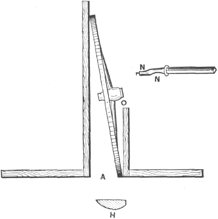
Fig. 117—Example of a Wheel Set so as to be Thrown under the Plumb Line, with an Indication of the Resulting Wear upon the Axle and the Tire
Before a blacksmith can properly set an axle he must have a rule to be governed by, and the principle upon which the rule is based should be fully understood. The foundation principle underlying axle setting is the “plumb spoke.” What I mean by “plumb spoke” is fully illustrated in Fig. 118. After the axles are set, place the wheels upon the axles, standing them upon a level floor as at A. If the square is on a line with the spoke as shown by B, what is called a plumb spoke is obtained. If it is desired to know how much swing the wheel has, a larger square is to be used, as shown by C on the opposite side of the wheel. The space F shows the amount of swing. Fig. 117 shows a wheel thrown under the plumb line, as indicated by the space between the top of the small square and the spoke marked O. A in this illustration shows the amount of swing. Fig. 119 shows a wheel which is thrown out of the plumb line as indicated by the space B.
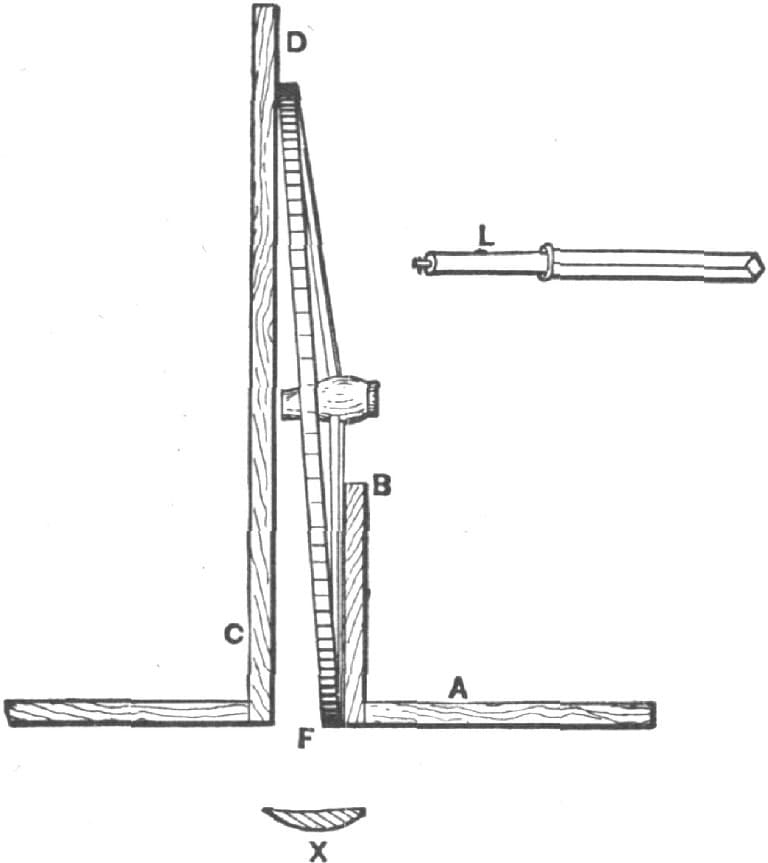
Fig. 118—A Wheel Set to a Plumb Spoke, Showing the Swing, and also Indicating the Resulting Wear upon Axle and Tire
My custom in setting axles is to set the wheels under sufficiently to make them run plumb spoke when loaded and in use. For a one-inch axle, five foot track, I set the wheels from three-eighths to one-half inch under plumb. If the axle arm has one-eighth inch taper, I gather the axle a quarter of an inch to the front, one-eighth inch to each wheel. A tapered spindle should always be gathered to the front. If it is not so gathered the wheels will have a tendency to crowd against the axle nuts, producing friction. Gathering tapered axle arms does them no harm; it is the abuse of gathering that spoils many jobs. In welding axles always have both front and rear axle of one length. Dish the front wheels just as much as the back wheels are dished at a corresponding height. This will give the back wheels more swing across the top than the front wheels, but the back wheels will have the same amount of swing at the same height as the front wheels. If the axles are set under alike the wheels will track.
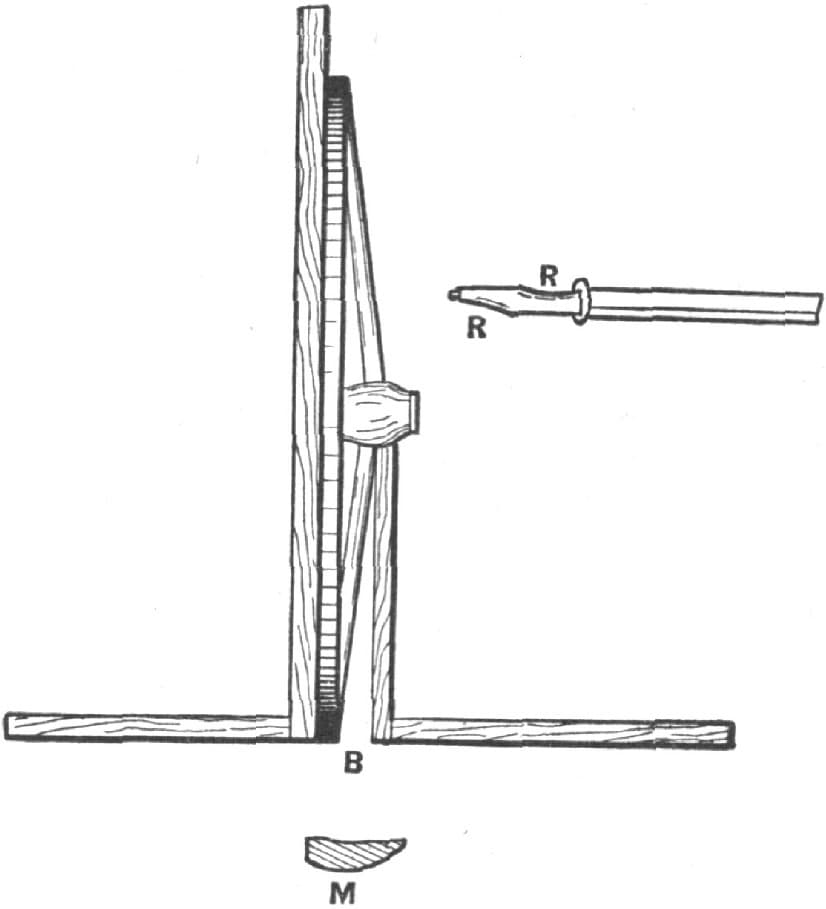
Fig. 119—Example of a Wheel Thrown Out of a Plumb Line, and Showing the Consequent Wear upon the Axle and the Tire
In setting axles I never pay any attention to the swing. Plumb spoke is the rule I work on. As already mentioned, I set axles somewhat under plumb spoke, varying from three-eighths of an inch to five-eighths of an inch, the amount depending upon the size of the axle and the width of the track. As to the gather of axles there are various opinions. From close observation during many years of practical experience I believe that gathering axles to the front is necessary where tapered axle arms are used. The amount of gather depends upon the taper of the arm. The object of setting axles under plumb is to get an even bearing upon both box and spindle. This is done in order to reduce friction. In like manner axles are gathered so as to obtain an even or horizontal bearing, also to reduce friction. If a wheel is set as much under plumb as shown in Fig. 118 the axle will wear as shown by N N, while the tire will wear as shown at H. If the wheel is set as in Fig. 119 the reverse will occur. The axle will wear as shown by R R, and the tire as shown by M. If the axles are set so that the wheels will run plumb spoke, as shown in Fig. 118, the axle arms will wear evenly as at L, and the tire will wear as shown at X. From this it will be seen that axles must be set under plumb, and that they must be gathered enough to give even bearings on both box and axle. Not until this has been done will friction have been reduced to the smallest possible amount.
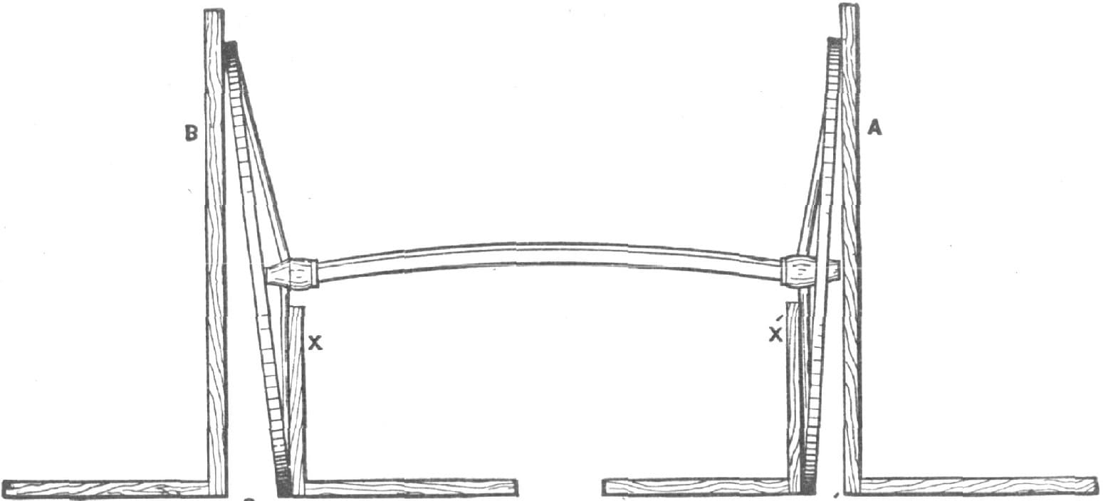
Fig. 120—Example of Wheels having Different Amounts of Dish Placed upon an Axle, so that Both Present a “Plumb Spoke”

Fig. 121—Gauge for Setting Axles, Described by “H. R. H.”
Fig. 120 shows two wheels of different dish, in position upon an axle. The wheel marked A has a half-inch dish, while the wheel B has a dish of one inch. Both wheels are set upon “plumb spoke” as shown by the squares X X. At O and O is shown the amount of swing which the wheels have at the top.
Fig. 121 shows the construction of an axle gauge which is made of steel. The long part X is made of one and a quarter by five and six-tenths. The parts A, B and D are made of seven-eighths by three-sixteenths. The gauge shown may be used for any kind of an axle, whether tapered or not. The part C is made as shown by C in Fig. 122, and is fastened to the bar with a set screw. In changing the gauge from a wide to a narrow track, the set screw of C is loosened, which permits the part to be moved along the bar as required. At the opposite end of the gauge a frame is arranged fitting close to the arm of the axle as shown. The side A is for the underset and B is for the gather. At O and O in Fig. 122 the construction of this part is shown. At D, Fig. 121, a slot in one of the pieces is provided through which a bolt is passed from the other. By this means the gauge is readily adjusted to suit axles of different tapers. As a part of the adjustability of the gauge it should be remembered that each of the four corners of the frame is held by a set screw, provided with a jam nut. A gauge of the kind here described can be made by any smith in two hours’ time, and the cost may be estimated as not exceeding one dollar and a half. —By H. R. H.
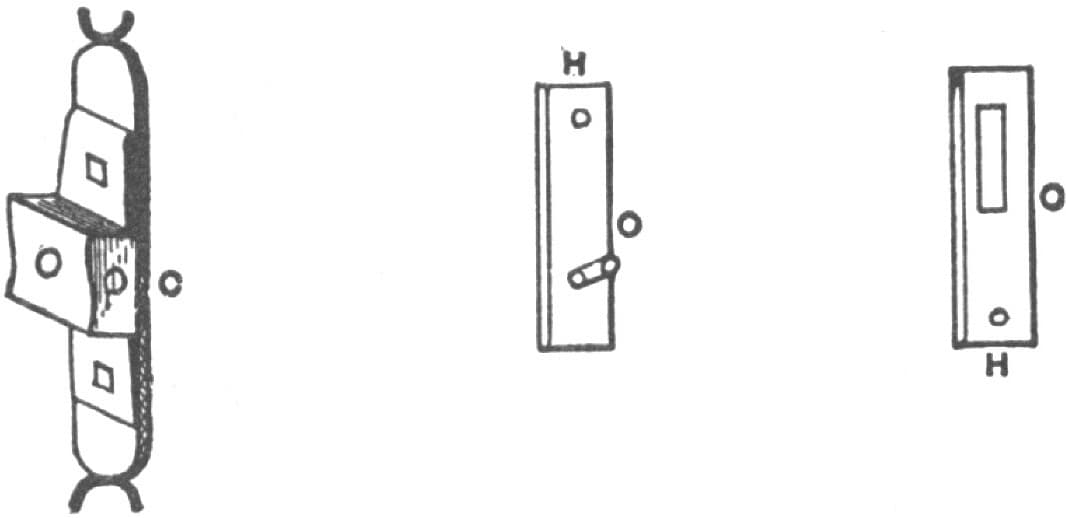
Fig. 122—Details of Construction of Axle Gauge Shown in Fig. 121
Setting Axles.
PLAN 1.
I have always understood the term plumb spoke as meaning a plumb line passing through the center or middle of the under spoke, in the direction of its length when the wheels are placed upon the axle, and standing upon a horizontal plane. I believe the center line is the foundation principle underlying axle setting. I believe so because it affords a positive point from which to work. Now, if I place the square on a line with the spoke, as directed by those who plumb their spoke by its back, the lines drawn at right angles from the spokes, Fig. 123, will clearly show the variableness, of the rule.
To be governed by the center line, of which I have spoken, gives results that are certainly more reliable. If, in practice, it is desired to set the spokes of wheels under or out from a plumb line, we can do so; but at the same time we have the advantage of a positive point from which to calculate our departure from a plumb spoke.
I will say, in favor of the former rule, that when spokes are used whose back and front sides are parallel, or nearly so, there could be no serious objection to it; but when the various tapers found on spokes are considered, and the great variety of wheels made and in use, I think a line through the center of the spoke the most practicable line from which to work.—By F. W. S.
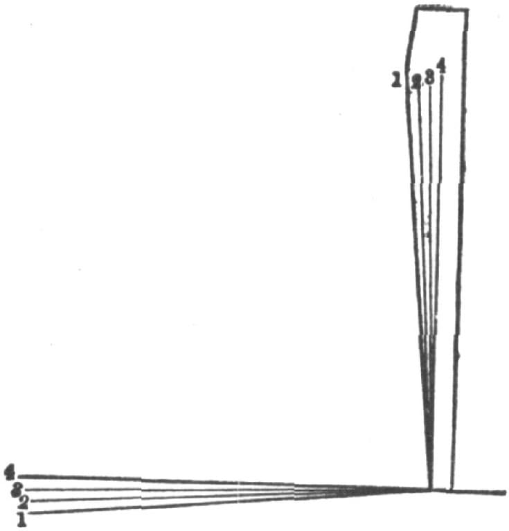
Fig. 123
Setting Axles.
PLAN 2.
I am a blacksmith, and I speak with particular reference to iron axles. It is evident, however, that what is applicable to them may be used also upon wood axles. The gauge I shall describe may be applied to any kind of an axle.
It is evident to anyone who has given the matter the slightest thought, that if axles should be made parallel—that is without taper—and the wheels straight—that is without any dish—no set would be required. It follows, therefore, that the main point to be kept in mind in considering this question is that a line drawn horizontally through the center of the axle from shoulder to shoulder (not through the spindles) should always stand at right angles to a line drawn perpendicularly through the center of the lower spoke in the wheels when set up. To bring about this relationship of parts, the taper and length of spindle, and the height and dish of wheels must each and all be taken into consideration. By the use of the gauge illustrated by Fig. 124, and by observance of the rules I shall present, the above result may be obtained with the utmost precision and in a very brief space of time. Referring now to the sketch, A is a piece of white wood about seven feet long, four inches wide and one-half inch thick. B is an iron about four and one-half feet long, one inch wide and one-eighth of an inch thick. It is offset at C about five inches, and is fastened at that point by a screw, upon which it turns freely. From D to E the iron is straight and smooth on the edge. From E to F it is fitted with a circular slot, depending upon C for a center. Through this slot a bolt provided with a thumb nut F is passed, and is so arranged that while the iron may be moved freely in either direction, it can be readily fastened in place, by means of the thumb nut, at any point. G is also made of iron, and is constructed with a slot through which the wood A passes. A thumb screw, indicated in the sketch, serves to fasten it upon the wood at any desired point. The ends of G are made to come the same distance from the edges of the wood as the space between the wood and that part of the iron first described, shown between D and E.

Fig. 124—Gauge for Setting Axles Described by “Hand Hammer”
Having learned the gauge, the next step is to adjust, so as to adopt it to set some required axle. First slide G upon the wood A until H rests upon one spindle at the shoulder, while D rests upon the other spindle at the collar. Suppose, for example, that the spindle is nine inches long from shoulder to nut, and that it has three-sixteenths of an inch taper. The taper must be ascertained by the callipers. Find nine inches on the bar B, measuring from C. For facilitating this operation, I have the bar graduated along its upper edge, as shown in the sketch. At nine inches, ascertained as above, move the bar upward three thirty-seconds of an inch, or, in other words, just one-half of the taper. The effect of this movement upon the iron is to move the edge D C correspondingly, since it revolves upon C, resulting as shown by the dotted lines a a1. Suppose, further, that the wheels in question are four feet two inches in diameter, and have one inch dish. At a point on the graduated bar B, twenty-five inches or one-half the diameter of the wheel from C, slide the bar B from its present position down one inch, or the full amount of the dish; as indicated by the dotted lines b b1, and fasten in this position by means of the thumb nut F. When the gauge has been adjusted in this manner the axle is to be heated and bent at the shoulder, until the straight edge from D to E will bear evenly along the under surface of the spindle, while the iron G rests at H, upon the opposite spindle at the collar. After one end has been set in this manner, turn and repeat the operation for the other. By this means a plumb spoke will always be produced.
Upon the opposite edge of the gauge, Fig. 124, I have a device for adjusting the axle to the gather, which I vary from one thirty-second to one-eighth of an inch, according to circumstances—the more taper and dish, the more gather is required.—By HAND HAMMER.
Setting Axles.
PLAN 3.
I wish to say a few words about setting iron and steel axles. In the first place the tires on the wheels should be perfectly true, so that there will be no swinging back and forth while hanging on the spindles. If the axles are to be arched, make the arch as desired and they are then ready to be set or to receive the under and front gather. In doing this I first bend them with the hammer as near to the shape as possible, then put the wheels on spindles, and next use the straightedge to see if the spindles are bent properly. I first drop the measuring stick on the floor to see how far apart the wheels are at the bottom. I then raise the stick up to the butts of the spokes. Between the rims and the butts of the spokes the distance must be the same when they go in the hubs as shown in Fig. 125. This insures a plumb spoke. On the front end the gather should be half the width of one tire (when it is not over one and one-half inches wide). The narrower the tire the smaller the spindle should be.
To ascertain if the spindles are bent alike measure with the measuring stick from the back of one hub to the top of the tire wheel opposite, as shown at C in the illustration, and then reverse the stick as at D. This enables you to tell if both wheels stand alike or not, and also shows just where to bend the one that is not right. Measure in the same way at the front, and this will enable you to make all wheels stand alike.—By J. W. KEITH.
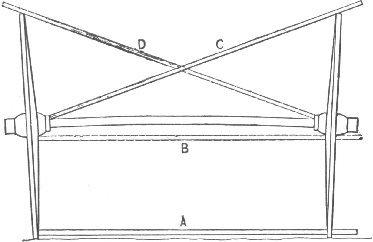
Fig. 125—Setting Iron or Steel Axles by the Method of J. W. Keith
Setting Axles.
PLAN 4.
I think my axle setter, Fig. 126, is a great improvement over the old straightedge, as it is easily and quickly adjustable for any angle required. It is made of one-half inch square iron. For the joint, use a common carriage top stub joint; make the slide A three-eighths of an inch by one-eighth of an inch. No other explanations are necessary.—By C. H. HEATH.

Fig. 126—Setting Buggy Axles by the Method of C. H. Heath
Setting Axles.
PLAN 5.
In setting axles I use two tools: A, in Fig. 127, is a straight stick of hard wood, about five and one-half feet in length and one and one-fourth inches square. B is a piece of iron, ten or twelve inches long and five-eighths of an inch square, drawn down to one-half inch and perfectly round, making a good collar with a nut at the end. About two inches from the end of the wood a hole is bored, and the iron bolted in just tight enough so it will swivel to take up the angle when the gather is made on the axle. At C is a slot in which works the half circle. In the slot is a steel thumb-screw with a sharp point. Before the slot is made the iron should be upset at that point, so as to make it stronger. There is another slot at the lower end, at D, in which is inserted the straightedge E, both being fastened with a rivet. If the half circle is properly made and welded at the straightedge at F and G rightly, all it needs after is a little filing and it is ready for use. H, in Fig. 128 is another piece of iron the same length as B, with a square loop at the top made to fit the wood snugly, and in which is inserted a thumb-screw, so as to hold it at any length required. At the lower end of the iron is a crotch, which is made to prevent the tool from slipping off the axle when in use. I think this explanation is sufficient for any good workman.
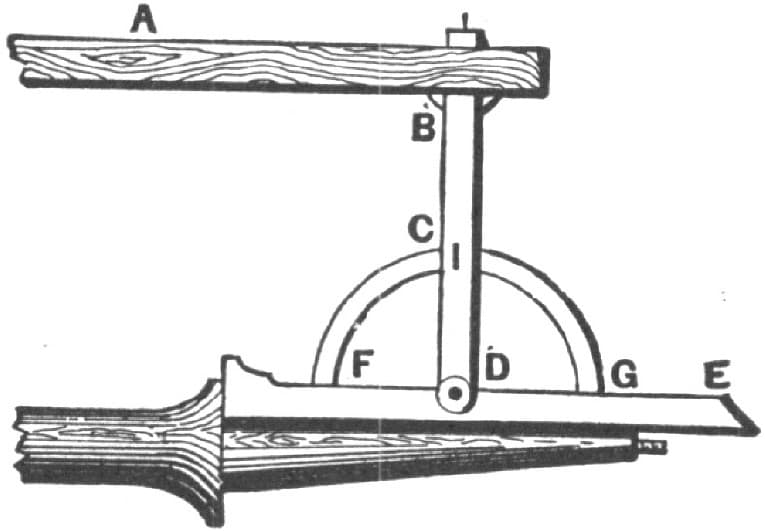
Setting Axles. Fig. 127—Showing a Tool Used for the Purpose by “M. D. D.”
Many years ago, when I worked East, I used a tool to set axles very different from the one just described, and I happen to know that tool is in use in some places now. Nearly thirty years ago, when I first came West, I found the tool I have just described in use; so whatever may be its merits, I feel assured there is no patent on it. I know the tool to be good and handy, and, if taken care of, will last a lifetime or more.—By M. D. D.
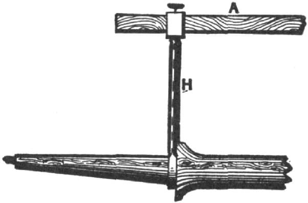
Fig. 128—Another Tool Used in Axle Setting by “M. D. D.”
A Straightedge for Setting Axles.
For setting axles I use the straightedge board with screws as shown in Fig. 129. I set the axles level on the bottom, with no gather, and find that they will run better so than when set in any other way.—By W. H. H.

Fig. 129—A Straightedge Board, Made by “W. H. H.,” for Setting Axles
A Gauge for Setting Axles.
There is no guesswork about my method, for it will always set an axle correctly.
Make a batten as shown in Fig. 130, and of the following dimensions: Five feet six inches long, fifteen inches deep in the center, and tapered from the center each way to three inches deep at the ends. The thickness must be five-eighths or three-fourths of an inch. The material should be some kind of dry wood that will not spring or warp. Then set four common wooden screws two inches long at A A, A A, the distance between to be the width of the arms on the axle. Have the end marked S for the side gather, and that marked B for the bottom gather or set, and, after fitting to the axle-bed, set the wooden screws on a line in the edge of the batten, leaving the point screws one-eighth off a straight line or whatever gather preferred. It does not matter what shape the axle is between the shoulders, this gauge will make the arms exactly the same by inverting from arm to arm. Never strike the arm with the face of your hammer, but use a piece of hard end wood, set it on the arm and strike the wood. The smooth surface of the arm may be spoiled by the lightest stroke.—By A. D. G.

Fig. 130—A Batten for Setting Axles, by “A. D. G.”
Setting an Axle Tree.
First get the length of arm on a straightedge and mark as shown at B in Fig. 131 of the accompanying sketches. Next get one-half of the height of the wheels with the tire on, and get the dish of the wheel marked as shown at C. From the dish mark draw a line across the arm mark to the point indicated by A. Next get the taper of the arm, which, by way of illustration, we may call one-eighth of an inch. Take one-half of the taper, that is, one-sixteenth of an inch, and mark back from the line mark at B. Then place the rest on the straightedge with the joint corner at D, and mark to the point of the straightedge at A, which will give the dip of the axle arm for a plumb spoke.

Setting an Axle Tree. Fig. 131—“T. C. B.’s” Manner of Using a Straightedge in Laying Off an Axle

Fig. 132—“T. C. B.’s” Adjustable Gauge for Setting Axles
Fig. 132 represents the gauge, the use of which is described above. It is so simple in its parts that very little description is necessary. The bar is one and three-quarters by one and one-half inches in size. The standard with thumb-nut shown at the right is six and three-quarter inches in height and is fastened to the bar by a slot twelve inches in length. The adjustable gauge at the opposite end is made six and three-quarter inches in its shorter arm, to correspond with the length of the standard, while the long arm is made thirteen inches, or of a convenient space for gauging; the bevel is as above described.
For this end of the gauge I have used an old carriage iron, adding only the thumb screws and other parts necessary to adapt it to its present purpose.—By T. C. B.
A Gauge for Setting Iron Axles.
I have a gauge for setting iron axles which I find very handy. Take a piece of bar iron, Fig. 133, one and one-quarter by three-eighths or one-half inch, and about seven feet long. Next make a piece like Fig. 134, with a slot to fit on the long iron, so that it can be slipped along it easily. In one side put a thumb screw, so that it can be held firmly at any point. Now take the long piece, and forge one end back about seven or eight inches, as seen in Fig. 134. Forge three inches of the end down to about half an inch round, then cut threads and put on two caps, as seen in Fig. 134. Then make Figs. 135, 136 and 137, which go to make up Fig. 138. The piece shown in Fig. 135 has a slot, and is intended to slide on the long rod, Fig. 133, also holes in each end for rivets. Fig. 136 is made similar to Fig. 135, excepting that the slot in the center is longer. There are two pieces like Fig. 137, and when they are all riveted tightly together we have Fig. 138. Then take Fig. 138, put it on the end of Fig. 133, and with Fig. 134 on the other we have the gauge complete as seen in Fig. 139. The length of the axle is regulated by Fig. 134, which slides along the bar, and Fig. 135 works by tightening or loosening the end tap, and thus gives the spindle the set you want. —By A. G. B.

A Gauge for Setting Iron Axles. Fig. 133—The Long Bar with Taps on End

Fig. 134—The Gauge which Slides on Fig. 133

Fig. 135—The Inner End Piece for Fig. 138

Fig. 136—The Outer End Piece for Fig. 138

Fig. 137—The Top Piece for Fig. 138
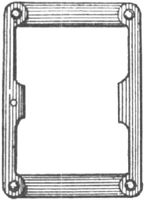
Fig. 138—The Frame that Goes on End of Fig. 133

Fig. 139—The Gauge Complete
A Simple Axle Gauge.
Take a piece of clean body ash, six feet long, four inches wide and half an inch thick, and dress the sides and edges to a straight line and parallel, as in Fig. 140 in the accompanying illustrations. This finishes the gauge bar. Next begin the iron work by taking band iron, one and a quarter inches wide, one-eighth of an inch thick, and making two pieces as in Fig. 141. The part A should be from corner to end five inches long, the slot B three inches long, five-eighths of an inch wide. The part D should be two and a quarter inches long from the corner to the end; the security hole a half inch from the end. The plane C should be made twelve inches long from corner to corner. Then make the iron shown in Fig. 142, A A, the outer portion forming the recess B; the swell is for the insertion of set screw rests, C C, for setting on the axle spindle. To make this iron, take two pieces three-quarters of an inch by one-eighth of an inch, as shown in Fig. 143—A A, the ends; B B, the halves of the recess—and then weld on the swell C, drill it and fit a set screw. Then open the unwelded ends so that they measure each one and three-quarter inches from the bar to the center of the curve, as at C C in Fig. 142.

A Simple Axle Gauge, as Made by “Iron Doctor.” Fig. 140—The Gauge Bar
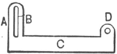
Fig. 141—The Angles
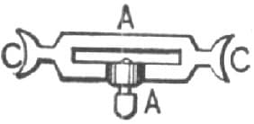
Fig. 142—The Standard
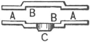
Fig. 143—Showing the Two Pieces Used in Making the Iron
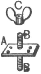
Fig. 144—Showing the Iron Parts for the Other End of the Gauge Bar
Next make the parts shown in Fig. 144, by welding a five-sixteenths of an inch bolt, one and a half inches long, into a plate of band iron two inches square by one-eighth of an inch thick, welding in a tool. On the opposite side jump (weld) another bolt of the same dimensions, as at A, which is the plate, B B being the bolts. In the plate drill four holes and countersink them for three-quarter by nine-inch screws, and then fit on each bolt a thumb nut C. When this piece of furniture is complete let it into the gauge bar at the end marked X in Fig. 145, distant from the end of the bar to the center of the bolt two and a half inches, and in the center of the width of the bar, one bolt passing through the wood. Next cut two hard leather washers one and a half inches in diameter, with five-sixteenths of an inch hole, and two iron washers one inch diameter with five-sixteenths of an inch hole. The parts shown in Fig. 142 are placed on the end of the bar marked Y, Fig. 145, and secured to it with the set screws. Next place one of the axles as at F, B, E, on the bolt and apply a straightedge so that when the end marked F is distant on the outer edge one and three-quarter inches from the gauge bar, and the other end of the straightedge rests on A, you can bring down that end to strike on the straightedge, as shown in the dotted line L, which gives the exact position to insert the securing bolt. Both sides are finished in the same manner, the dotted line K serving as did the dotted line L.

Fig. 145—The Axle Gauge Completed
The gauge is then complete, and by means of the set screw H you are prepared to move the standard, shown in Fig. 142, along to any position on the wood gauge bar, and so allow of it accommodating itself to suit any length of axle.
The tool is operated in the following manner: With a pair of calipers take the taper of the spindle, then be sure that the plane B, Fig. 145, is on a line with the standard A, as much as the spindle tapers from the shoulder to the point next the thread. Move the plane B from the bar A at its end, as shown by the dotted line M. Next get the dish of the wheel by placing a straightedge across the face of the wheel and measuring from the inner side of the straightedge to the face of the spoke at its intersection with the hub. If the spokes are dodged or staggered, take your measurement from the inner side of the straightedge to half the distance of the dodge of the spokes. Then move out the plane B, Fig. 145, just as much more as your wheel dishes. Then place your standard or measure at the shoulder on the upper side and apply the plane B to the other spindle. When it—the spindle—conforms to plane B the spindle is in a position to give you a plumb spoke. For ascertaining that your axle sets alike on both sides—that is back and front—move out the plane C as much as your spindle tapers. If the axle spindles are straight they will agree with the gauge on both sides.
If the spindle has no taper the calipering process is not necessary. To set your axle narrower than a plumb spoke, drop the plane a trifle more. To create gather, set the plane C out a trifle and apply to the rear part only.—By IRON DOCTOR.
How to Set Buckboard Axles.
Buckboards are used a great deal in the State of Vermont. If the axles are set correctly they are easy running, having the additional advantages of being light and cheap.
We will commence with the forward axle. On account of the buckboard settling or sagging when laid, if the axles are fastened at right angles with the slats or boards the forward axle will turn back and the hind axle forward; so if the forward axle is set the same as for a wagon, the axle being rolled back will have too much gather. In my opinion the forward axle ought to be set with no gather at all, and if it be necessary to turn the arms down, they ought at the same time to be turned back somewhat. From this statement of the case it is evident that a man should use his own judgment in a point of this kind. The rear axle, for reasons given above, will roll forward, which, if the axle is set as for a wagon, will serve as backward gather, which any blacksmith knows is not right. To remedy this the hind axle ought to have considerable gather. This must be calculated with reference to the sag of the buckboard. It should have enough, so that when it is loaded the wheels will have no more tendency to run off than to run on. —By A BOY BLACKSMITH.
To Lay Out Thimble Skein Axles so as to Secure Proper Dish to the Wheels.
If you want to stand the wheels on a plumb spoke, the proper plan is to use a skein that has a plumb spoke taper. All others are imperfect, and in my opinion are not fit for use. All the skeins with which I am acquainted, excepting one brand, are tapered too much. They require the outer end to be raised up in order to arrive at a plumb spoke. Now if the outer end of the arm be raised higher than the shoulder, the tendency will be to work the wheels off, which requires an unnecessary amount of gather to counteract. This causes the wheels to bind, and results in heavy draft. I will now present my way of making thimble skein axles. I first take a thin piece of stuff, say five-sixteenths of an inch thick, and shape it to fit skein as shown in Fig. 146. I then draw the perpendicular lines 1, 2, 3 and 4 shown in the sketch. I then lay out an eight-square or octagon for each of these lines, as shown in Fig. 147. This is done by making a square with sides of the length of the cross section. Draw the diagonal lines. Set the compasses to one-half the length of one of these diagonal lines, and from the corners of the square as centers strike arcs, cutting the sides of the square as shown. Connect the points thus obtained, which will complete the figure. Mark points on pattern corresponding to lines 1 and 2 of Fig. 146. Cut a small notch at end at 1, and prick through at 2. Next draw a line with the bottom points the entire length of pattern. Then draw lines at upper points from 1 to 2, after which make eight square points on lines 3 and 4. At top make small hole through and draw line from 3 to 4. Then draw a line through center of 1 and 2 the whole length of pattern, as shown dotted in Fig. 146. With the pattern thus prepared, take the axle, which should be straight on the bottom. Mark across the center as shown by 1 in Fig. 148. Measure from this line each way to where the inside of skein is to come. Draw the lines 2, 2 through these points. Through the centers of these lines draw C, D as shown. Measure back from where skein is to come the space of twenty inches from each of the lines indicated by 2. Make marks one-eighth of an inch back from center line as shown by 3 and 3. Place a straightedge on the center of 2 and the point 3, which is twenty-eight inches away, and draw line from 3 to end of stick. This will give the gather. Now place pattern upon axle so as to have the center line on pattern on gather line of axle. Mark against pattern for lines to taper to; mark by notches at end and through holes on line 2, by which to get lines for reducing the corners. Then mark both sides with pattern as shown in Fig. 148 at A and A. Next work off the top, and then lay out the top by pattern in the same general manner, after which take pattern and mark sides of axle; work off the corners; then the axle will be ready to round up. That there will really be very little to do may be seen by inspecting the lower part of Fig. 147. If it is desired to have the timber to last well inside of the skein, point it with red lead and varnish it before cutting on the skein. This treatment of the wood will prevent the rust from injuring the wood.—By * * *
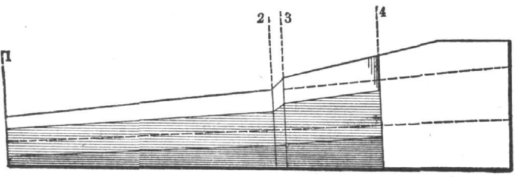
Fig. 146—Pattern for Laying Off Axles to Receive Thimble Skein
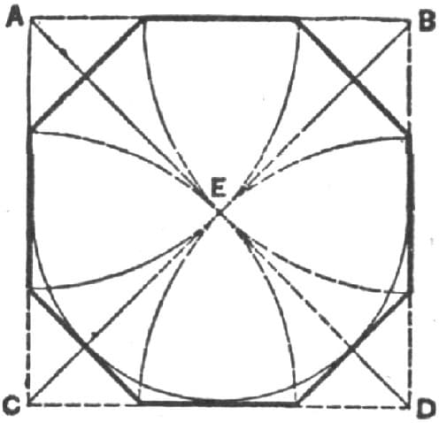
Fig. 147—Diagram of Cross Sections through Axle

Fig. 148
To Set Axle Boxes.
The best plan I have ever found in fastening a pipe box that has turned in the hub and worn away so that it cannot be wedged, is to clean out all the grease and rotten or splintered wood, wrap the small end of the box with oilcloth or leather, and drive it tight in the hub. Then center the large end just as you want it, and take good clean sulphur, perfectly clear of sand and dross, melt it and pour around the box. I have found this to hold a box when wedges would not. The sulphur must be pure and clean.—By J. F. McCoy
How to Lay Off an Axle.
Suppose we have an axle to make for a wheel with a thimble like that shown in Fig. 149 of the accompanying illustrations, three inches in diameter at shoulder, and one and one-half inches at the point. First get the length of the axle between the shoulders, and the amount that should be taken off the point of the spindle. To do this set the wheels up as shown in Fig. 151, on the floor or some suitable place, and just as you want them to set on the axle when finished. Be sure to set them on the floor the right distance apart, which is five feet from “out to out” in this locality, though it varies in different places; and confine them in this position. Then take a straightedge, straight on the bottom, but beveled on top, as shown in Fig. 150, so it will easily enter the box. Put it in the hubs as shown in Fig. 151. See that it rests on the point on each box at P. It will not touch the back part of the box at A. The distance from the bottom of the box to the straightedge at A is the amount to be taken off the point of the axle at B, Fig. 153. The distance between the boxes on the straightedge is the distance between the shoulders of the thimbles when on the axle. Mark the distance on the axle at C, C, Fig. 153. Then get the thickness of the thimble at the shoulder between D and E, Fig. 149. Do this by measuring from F to D, outside, and from F to E, inside. The difference in these measurements is the thickness of the shoulder between D and E. Say it is one-half inch, mark this inside C, Fig. 153 at G, and mark across the tops and down the back side of the axle at G, as here is the place to cut down the shoulder. From G mark the distance from E to F, in Fig. 149, to H in Fig. 153. Here is where the thimble will come on the wood. Then get the distance from E to F, Fig. 149, inside, and having this, then measure from H, Fig. 153, toward the point and saw off one-half inch shorter to prevent the wood binding at the point. Then draw a line parallel with the bottom of the axle, and three eighths or one-half inch from the bottom, as at J, J, Fig. 153. This is the line to measure from. From the intersection of J, J, and G measure the diameter of the thimble inside on G, which in this case would be three inches. From J, J, at the point, measure the distance of the straightedge from the box at A, Fig. 151, represented at B, B, Fig. 153. Draw a line from F through the intersection of J, J and G to the bottom of the axle, which is to be cut off to this line. From one and one-half inches from B, this being the inside diameter of thimble at point, draw the line K to the line G, three inches from J, J. Get the distance from L to E, Fig. 149, and mark it on G, Fig. 153, above J, J, and draw a line from this to H. Saw down the shoulder and trim off, as in Fig. 156. Then turn the bottom up, as in Fig. 152, and draw a line through the center from end to end. From this line at the point of the spindle measure the gather, if you want any. Make a mark in front of the center line one-eighth of an inch—one-sixteenth is better for gather—and from this mark draw the line to where the line H intersects the center; and from M measure each way three-fourths of an inch at the end of the axle, this being one-half the diameter of the thimble at the point, and from these points draw the lines H, H at each side of the axle, as seen in Fig. 152, trim off as in Fig. 157, and round off to fit the inside of the thimble.
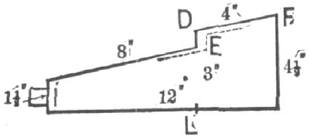
How to Lay Off an Axle. Fig. 149—Showing the Thimble

Fig. 150—The Straightedge
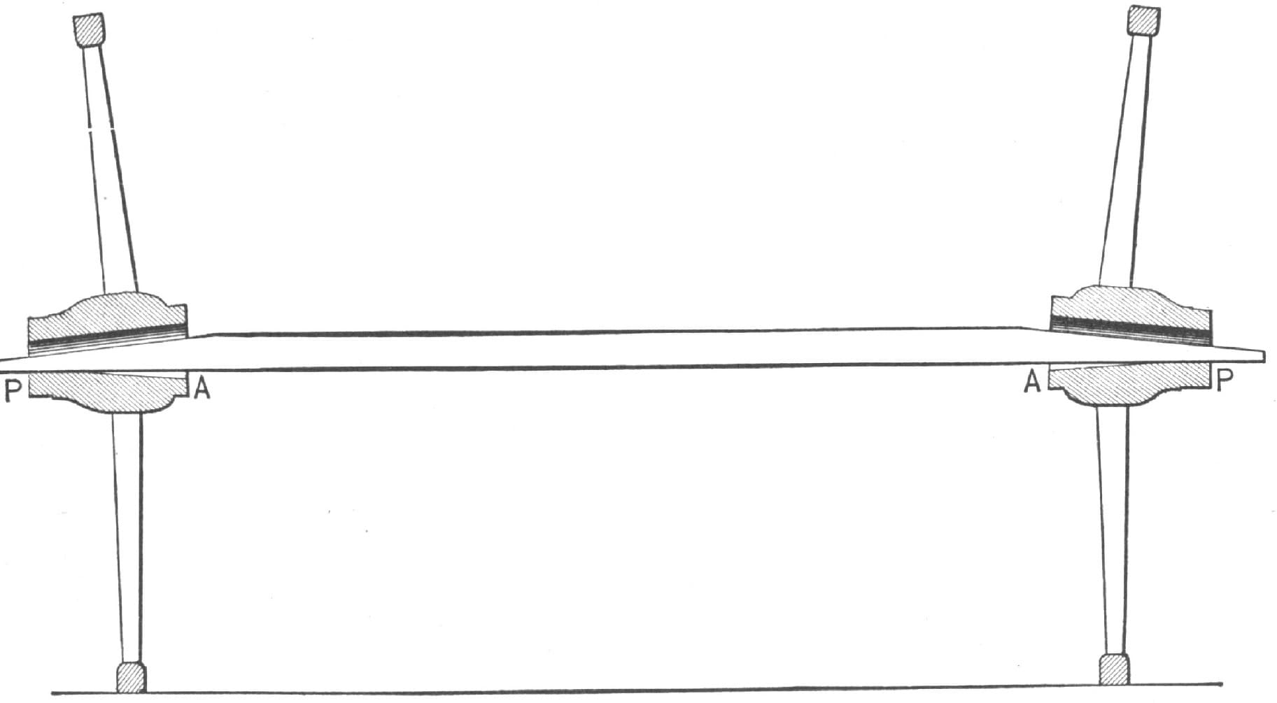
Fig. 151—Showing How the Straightedge is Used

Fig. 152—Showing the Method of Marking for the Gather and Trimming to Fit the Thimble

Fig. 153—Showing the Method of Measuring for Cutting Down the Shoulder and Fitting to the Thimble
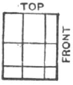
Fig. 154—Showing the End of the Axle Before it is Finished
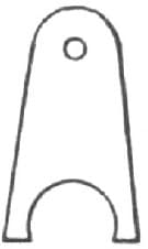
Fig. 155—A Gauge Used in Rounding the Spindle at the Shoulders

Fig. 156—Showing How the Shoulders are Made

Fig. 157—Showing the Axle Trimmed
I find the gauge represented in Fig. 155 to be a very handy tool in rounding the spindles at the shoulders. It should be made of thin board and of the exact size of the inside of the thimbles at the shoulders. Fig. 154 represents the end of the axle before it is trimmed off. The dot represents the center of the spindle.
In the foregoing directions I have tried to show how to lay off an axle so that any person can understand me. I have not said whether the spokes should be plumb or not, nor just what the gather should be. This is the simplest method with which I am acquainted. It requires only the square, straightedge, scratch awl or pencil, and compasses or calipers. —By M. J. S. N.
Setting Wood Axles.
I have worked in a good many shops, but have never yet met anyone who employed the rule I use. I will describe my method, for the benefit of all brother mechanics who are interested. I draft my axles according to dish and height of wheels. I measure from the hub or collar on spindle, half of the diameter of the wheel. I then draw a line about one-eighth of an inch more than half of skein at collar, inside from bottom edge; I draw it more than half, in order that the taper on bottom edge of axle may run back to the rim on the skein. I gather wood axles from one-sixteenth to one-eighth of an inch, and set the hounds so as not to roll the axle in coupling or in its natural standing position. Referring to the diagram for explanation in connection with Fig. 158, it will, I think, make the rule as above given fully understood. Measure half diameter of wheel from F to B. Set compasses on line C B to get size of axle to fit skein. After obtaining inside size of skein set compasses to half diameter, and taper the axle to fit.—R. D. C.

Fig. 158—Setting Axles by the Method of “R. D. C.”
Making and Setting Thimbles on Thimble Skein Axles.
My rule for making and setting the thimbles on the thimble skein axle is, to make the bottom of the axle straight. Strike a line from one end to the other; get the size needed to make the spindle to fill the skein at the point; move the center up and forward one-eighth of an inch, retaining the original center at the shoulder; then proceed to lay off the spindle and dress off on bottom and back, tapering from the shoulder of the thimble to the point; then dress off the front and top until it fits perfectly, and put it on with white lead.
This rule is for straight wheels or those slightly dished; if much dished leave the spindle straight on the bottom and take one-eighth of an inch more off at the back. Of course the method must be varied to suit the wheels, so they may set perpendicular from the hub to the ground, giving them about one-eighth of an inch gather.—By D. W. C. H.
Thimble Skein Stay.
The closer two smooth surfaces come together the more they will cling to each other, forming a perfect joint; and so it is in fitting axle arms to thimbles. If you have no machine skein fitter, you will have a tedious job before you to make a perfect fit, but fit it you must as near perfect as possible. Bore a hole of the proper size to retain a firm hold on the thread of the bolt. Then give the arm a coat of red lead and linseed oil, which will stick tighter to the arm and thimble than any other cement I know of. This will fill the slight inequalities that still remain after the fitting, and will also prevent water from getting in and forming oxide of iron, which is injurious to hickory axles. If you have no press to put them on with, drive them on as firmly as you can, screw in your skein bolt, and your skein will stay.
Some blacksmiths make a bolt with a hole punched in the end to take the bolt that comes down through the bolster, with thread on the other end, and nut on to screw up the skein with. It is a bad way, to my mind, as it not only causes extra labor to let in the bolt in the arm, but weakens the axle where it should be the strongest.
Putting skeins on hot is not practicable. The skein expands and allows it to go on further than it should, and when the skein shrinks to its original size it is very liable to burst.—A LONG FELLOE.
Setting Skeins.
I first make my timber of the desired size, being careful to get it perfectly straight. I next find the center on the bottom and at each end, then take the straightedge and lay a straight line on the bottom and both ends. I next lay off each end to the size of the skein. I begin to lay off on the bottom and take an eighth of an inch more off the back than off the front. This will give a gather quite sufficient and will suit wheels with three-eighths or one-half inch dish. Some may think that I raise the point of the skein too much, but I raise it in order to get the wheels in three or four inches at the bottom.—By H. D.
The Gather and Dip of Thimble Skeins.
First straighten the axle on the bottom perfectly straight. At the back end of skein put a center prick mark, and taper axle from there to the end one-fourth of an inch and allow one-sixteenth of an inch for forward gather. I center with a fine seaweed line, which is better, in my judgment, than a straightedge. I learned to set skeins from the inventor of the first ones made.—BROTHER WOOD BUTCHER.
The Gather and Dip of Thimble Skeins.
My method for setting iron axles is to have the wheels four inches wider at the top than the bottom of track. To get at the gather use a straightedge, and give just as little as you can by measure, from the end of the axle to the straightedge.—IRON ROSTER.
Giving an Axle Gather.
Well, my idea of this matter is, that when I set an axle I set it so that the spoke from the hub to the ground will be plumb. If you will examine an axle which has no gather, you will see that it will wear on the back side next to the collar and on the front side next to the nut. We give it gather for the same reason that we give it tread, to make the bearings even on the axle. If it had no gather one wheel would be trying to get out one side of the road, and the other the other side of the road. This is my idea, and I give it for what it is worth.—By A. W. MILES.
Finding the Length of Axles.
No. 1. Measure from the back end of the hub to the face of the spoke, then double the length and subtract it from the width of the track. If dodging spokes, measure half the dodge. This gives the length between the shoulders.
No. 2. Take the distance of the track from center to center, and establish the length of the axle so that the hubs are the same distance apart less the length of one hub.
No. 3. To get the length of wooden axles between the shoulders, first measure from the face of the spoke to the large end of the hub (or where the shoulder comes) on each wheel; add these two distances together, and to this sum add the width of one spoke at the rim of the wheel. Take this amount from the desired track (from centers) and the remainder will be the length between shoulders in the center of arm on the front side. If the wheel is very dishing it will be a trifle longer on top and a trifle shorter on bottom.
No. 4. My method of getting the length of a wooden axle is to measure the width of track on the floor, and stand the wheels on the track, plumb up to the spokes, then measure from one hub to the other, which will give the exact length of the body of the axle, and when the wheels stand in this position I pass a straightedge through both hubs, and that gives the set under for the axle. I allow one-sixteenth of an inch for gather.—By J. D. S.
The Gather of Axles.
Spindles are tapered in order that the vehicle can go over uneven surfaces with the least possible binding or friction. The gather partially answers the same purpose, for without gather the motion of the wheel would carry it toward the outer end, causing binding or friction on the nut or linch pin. The gather serves as a support to the wheel, giving it the proper position under the load, so that it may be carried with the least possible strain. Too much gather is as bad as not enough. With regard to the proper mode of obtaining gather in iron axles opinions differ somewhat. Wheel measurement is generally resorted to. Some wheelwrights use a certain measurement for the axle for a wooden axle, no matter what the kind or height of wheel may be or how much taper the spindle has. Others use an axle set for setting iron axles, but in my opinion none of these axle sets is desirable unless the mechanic using it knows how to change it to suit the height of the wheel and the taper of the spindle. Surely if an axle be set for a wheel measuring four feet six inches, with a very small point, it would not be right for a wheel measuring three feet. Change the taper of a spindle and you change the gather. The accompanying illustration represents a method I use for attaining the gather, etc. In Fig. 159, A denotes the axle; B is a line drawn far enough up from the bottom to come to the center of the point of the spindle; C denotes the height of the wheel; D is the point where you obtain your gather. You ascertain the difference, or how much wider your wheels are at the top than at the bottom, when the under spoke is standing plumb, then you get the height of your wheel from the point of the spindle, measure half the difference in width of the bottom and the top of the wheels, draw the line G to the point of the spindle, then, using the line G as the center of the spindle, size your spindle at the butt and point and you have the proper gather. Give your spindle half as much gather forward as it has up and down and you will have a good running wagon.—By A. O. S.

Fig. 159—“A. O. S.’s” Method of Ascertaining the Proper Gather
Should Axles be Gathered?
Who was the first to “gather” an axle arm, or what led to the “gather” are questions not easily answered, but of all fallacies in connection with carriage building, none obtained a stronger foothold than this one of “gather.” Old-time wagon makers said it was to keep the wheel up to the back shoulder, and by so doing protect the linch pins, but their experience failed to sustain their theory. Yet the idea was handed down from master to apprentice, and until a comparatively recent date none undertook to question its necessity. Today the scientific builder ignores the gather entirely on all heavy coach axles, and reduces that on light axles to a minimum, recognizing that the only earthly use of the gather is the necessity of overcoming the throwing out of the forward edge of the wheel by the springing of the axle, one-sixteenth, or at the outside one-eighth, of an inch difference between the front and back of the felloe being all that is required. The true principle is to have the rims describe by their tread on the ground absolutely parallel lines at perfect right angles with the axle bed, and no wider than the true width of the tire. And just in proportion as the wheels deviate backward or forward from these lines, so is the draft increased.
Advocates of gather say that if the arms of axles were perfectly straight gather would not be needed, and it is because of the taper that the gather is necessary. They are not bold enough, however, to ask that the gather be made equivalent to the taper, and thus throw the front end of the arm on a line parallel with the front of the bed. If they do this they will set their wheels so much in that they would scarcely revolve at all on roads where they cut in to the depth of four to six inches.
Take an axle arm ten inches long, having a taper of one and one-quarter inches, or five-eighths of an inch each side, and set the arm forward to bring the front straight, the front of the wheels, if three feet ten inches high, would be six inches nearer together than the backs; a situation that none would venture to advocate because of the greatly increased draft. And yet every fractional part of an inch that would lead to that situation adds its percentage of the increased draft.
The revolution of the wheel is from an absolute center, even if the bearings be on a cone. So that the taper itself has nothing whatever to do with the running on or off of the wheel. A plumb spoke and a straight tread are the two essentials for an easy running vehicle. And it is time that the trade got rid of the “talking” chucking of the arm and the cramping “gather.”—By PROGRESS.
The Gather of Axles.
I am now in the shadows of fifty years. I have stood at the anvil for considerable over half of that time, and I want to say a word in regard to the gather of axles. As far back as the time the Coachmaker’s Magazine was published in Boston (in the fifties), I remember an article on the gather of axles that settled that question beyond controversy. I will state its points briefly:
The question was asked by the editors: “How much gather is necessary for the easy running of carriages?” It was answered by a number of the trade, and a division of opinion was made evident, and to settle the matter an inclined plane was constructed up which a buggy was pulled by a rope running on a pulley; upon the other end of the rope was a bucket into which were put weights enough to pull the buggy up, with five-sixteenths inch gather. The amount of weight in the bucket necessary for this was noted; then the axles were taken out and the gather changed, leaving one-eighth gather, and it was found that the same buggy could be run up the same incline with less weights in the bucket, which proved that a buggy with one-eighth inch gather would run easier than it would with five-sixteenths inch. I do not give my buggy axles over one-eighth inch gather. I set them about three-eighths inch under what I want them to track, if I want them to track four feet eight inches outside. That will give me a plumb spoke. I make them three-eighths of an inch narrower, because when I hang up the body and one or two persons get in, the axle will settle a little in the center, which will throw the wheels out correspondingly on the bottom, and so when on the road I have my track right and my spoke plumb.
Setting iron axles is a difficult job, whether the axle be light or heavy. A few years ago there was built in Central New York a heavy wagon to run on a plank road. Its first trip with a load disclosed the fact that something was wrong with the axles. They would heat and the team was obliged to labor very hard to draw the load. The wagon was returned to the shop and carefully looked over. The axles were measured and pronounced all right, but on the next trial the same results followed. The axles were taken out and another set put in with the same result. The wagon was finally taken to another shop and was looked over, the axles were measured, and the owner was told that if he would leave his wagon it would be made to run and without heating, and that the same axles would be used. Now note the result. The last man found about three-quarters of an inch gather. He took the axles out and reduced the gather as much as he could without leaving the wheels as wide in front as at the back. The axles after that ran all right and never heated. If a wheel runs on the front of the shoulder enough to cause friction it is just as bad, if not worse than if it ran on the nut by running out on the bottom. —By H. M. S.
Making a Wagon Axle Run Easily.
The younger members of the trade may be interested in knowing how to make a wagon that will run easily.
The secret of doing this is to get the set and gather so that the wheel will stand in such a position that it will not bind on the axle arm.
Set your axles so that the faces of the spoke will stand plumb, that is, so that the width close under the hub and the track on the floor will be the same, if the wheel stands under, the axle and will wear most on the under side-end, next to the collar and on the top side the end next to the nut. Or if the wheel stands out on the bottom the axle will wear vice versa. In either case it makes the wheel bind on the arm and, consequently, run hard. It also wears the tire thinner on the over edge.
A very small amount of gather is sufficient for ordinary axles. If the axle arm is as large at the outer end as at the collar it will not need any collar at all, but as our axle arms are made tapering it is necessary to give them a little gather, so that they will not tend to crowd the axle nut too hard. From one to three-fourths of an inch, according to the weight of the job, will generally be sufficient; a heavy axle having, of course, the most gather.
It is also very important to get the gearing together square and true.
The way many men judge whether a lumber wagon runs easily or not is by the chucking noise. You can easily make one rattle loudly by cutting away the hub so that the box will project one-eighth of an inch beyond the hub. This allows the box to strike the collar and so make an unnecessary amount of noise.—By BILL.
That Groove on the Top of an Axle Arm.
Fifty years ago quite the larger part of the axles made were not turned. The blacksmith bought the drafts in the rough, and fitted to each were two short boxes about one and one-half or two inches long. There were two boxes in each hub and a hole was punched for a linch pin. This was what was used mainly fifty or sixty years ago. But after a time there was an improvement on the box. One going through the hub was used, and these were called “pipe boxes,” and I can well remember when orders were received for axles like this: “Send me ten sets one and one-eighth by six and one-half axles with pipe boxes,” otherwise they would receive axle drafts. These axles with pipe boxes had a nut on the end. The nut had to be square with the square of the axle, and a hole drilled through the nut and axle. It seems but a short time since we could not sell an axle without this hole through the nut. But to the groove: When axles with leather washers began to be used, either half patent or a common axle with pipe boxes, these boxes were made to fit. They were ground on the axle to bear the entire length, so that the fit was perfect. With the box washered up with leather on each end, and the nut screwed up so that there was no play endwise, the box must be kept free from dirt to run easy. But dirt would certainly get in the box, and if there was no place for the dirt to stop it would in time become hard and stick the wheel. The groove was made to stop all dirt in the box and leave the box free to turn easily on the arm. Originally the groove was not intended for oil, but to catch the dirt.
There are those now who make axles with boxes ground to fit, and the groove is of great value. But when axles are made with boxes fitted very loosely, the groove is of no earthly use.—By C.
Broken Axles.
By far the greater number of broken axles in the larger towns take place just inside the hub of the wheel, where the square and round part of the axle meet, or at the shoulder.
Of the many broken axles which we have examined within the past two years, we have failed to find one which could be considered a new break. In almost every case at least one-half of the substance of the axle had been cracked through, leaving only the central portion to sustain the load.
Fig. 160 represents a very common appearance of an axle after it is broken. The lighter portion in the centre shows the new crack; outside of that will be a black and greasy surface, A, showing that the break had been under way for a long time and had penetrated to such a depth that the sound metal in the center was at last unable to stand the strain.
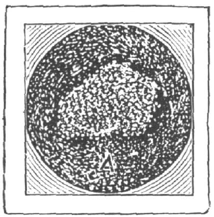
Fig. 160—End View of Broken Axle
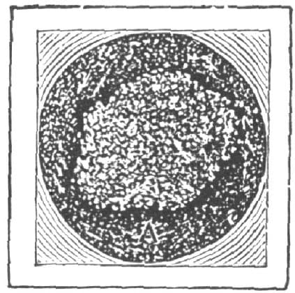
Fig. 161—End of Broken Axle, Dark Portion Showing Old Crack
Fig. 161 shows a different arrangement, where the axle has probably had a greater load, and the broken part bears a greater ratio to the old crack A than in the previous case.
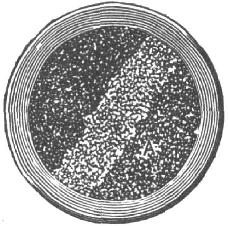
Fig. 162—Front Axle of Fire Engine. Dark Portions Show Old Cracks, Light Band the Final Break
Not long since, in running to a fire, a steam-engine was disabled and thrown on to the curb-stone by the breakage of the front axle. We examined the break and found the fractured part in the condition shown in Fig. 162. The body of the axle had been cracked from the two sides. These old cracks had worked toward the center until only a narrow strip in a diagonal direction was left, as shown in the engraving.
A large majority of people seem to think that with a heavy cart a broken axle is inevitable. Axles do break, and every teamster at some time finds himself laid up with a wheel in the ditch. We believe, however, that broken axles are not a necessity; and we have never seen an axle broken which, on examination, did not show faulty construction as the direct cause of the breakage.
A great deal of nonsense is current in regard to “crystallization” of iron when it is strained or has to bear constantly repeated shocks. The statement is often made, even in scientific papers, that iron subjected to even light blows will crystallize after a time and become weak and “rotten.”
The amount of strain which iron can safely sustain is measured by what might be called the spring of the iron. When, after a piece of metal is stretched and the tension taken off, we find that the iron goes back to its original size, no harm has been done. If the strain has caused the iron to become lengthened on one side so that it does not return to its original condition, it has been harmed and breaking has already begun. In all engineering structures great care is taken to proportion the metal to the load in such a way that the iron will never be strained to the point where it will take a “set.” In other words, when the strain is taken off the iron is expected to return without damage to its original form. “The limit of elasticity” is the limit of load which the iron will bear without being permanently stretched. As long as we keep well inside this point there seems to be no limit to the life of the iron. In fact, in ordinary practice, this limit is never reached.
Bearing this fact in mind, it is easy to explain how it is that axles improperly shaped break under light loads so easily and so frequently. If we take a bar of iron like that shown in Fig. 163 and bend it, the fibers all stretch along one side; and if we do not bend it so as to cause it to “take set” it returns to its original form without injury. If we now weld four pieces of iron upon this bar, in the form shown in Fig. 164, we shall find that when we undertake to bend it to the same extent as before, all the stretching of the fibers is concentrated at the one point A; consequently, an amount of bending which did not harm the plain bar will in this case break the fibers on one side or the other, at the bottom of the openings between the bars which were added.

Fig. 163—Plain Bar of Iron

Fig. 164—Plain Bar with Four Bars Welded Upon It, Leaving Gaps at Center
In this we have precisely the same effect as is obtained by nicking a bar of iron to break it on the anvil. In that case the bending of the bar is all done at a single point and the fibers break at the surface on account of the concentration of the strain. All the stretching has to be done at a single point. It is a well-known fact in carpentry that a large stick of timber, scored with a knife on the side that is in tension, will lose a large proportion of its strength. A sapling, two or more inches in diameter, if bent sharply can be cut off easily and quickly by a pocket knife, if the cut is made on the rounding side. A piece of timber, nicked as shown in Fig. 165, is in such a condition that the greater portion of the stretching when the timber is bent has to be done at the very point of the nick, consequently a few fibers have to take all the strain and yield quickly, and as others follow the breaking is rapid.

Fig. 165—Weakened by Nicking
We have seen that the single bar of iron is stronger when of equal section throughout than one of much greater thickness deeply nicked on opposite side. We have also seen that it is necessary to distribute the bending over a considerable surface, in order that the fibers of the iron may not be overstretched at any one point. Examinations show that car axles broken before their time have almost invariably been finished with a “diamond-nosed” tool, which left a sharp corner at the point where the journal joined the axle and where the metal was subjected to severe strain. Consequently, any bending which took place was concentrated in the metal at the corner, and a crack at once began. The means for avoiding this are to be found in so shaping the metal that the strains are not concentrated at a single point, but distributed along the whole length of the metal as much as possible.

Fig. 166—Axle with a Sharp Corner at the Point where Arm and Collar Meet
The broken axles that we have mentioned, as well as all that we have examined, have been, without exception, of the form shown in Fig. 166. By inspection it will be seen that the shoulder joins the arm with a sharp corner, and this corner invariably acts precisely like a nick in a bar of iron that is to be broken upon the anvil. Every blow or strain that bends the axle does all the work of bending at this point. Consequently a crack commences and usually runs all around the axle, as the blows come from all directions. Every successive blow tends to increase the depth of the crack, until at last the solid metal is so reduced in quantity that a heavier shock than usual takes the axle off.

Fig. 167—Well-Rounded Curve Between Arm and Shoulder
If, instead of finishing with a sharp corner, we put in what machinists call a “fillet,” or an easy curve, as shown in Fig. 167, the strength of the axle will be greatly increased and there will be much less tendency to break at the shoulder.
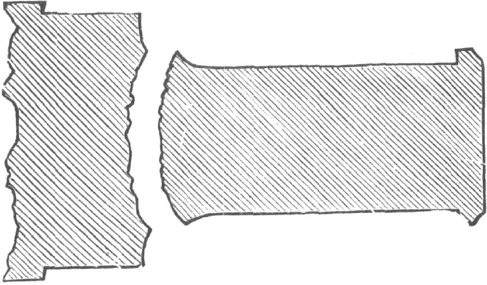
Fig. 168—Axle of Stone Car. Break Rounding Out into Solid Metal
Fig. 168 is a section of an axle which shows how greatly this rounding, or fillet, at the shoulder increases the strength. The illustration is of a very large car-wheel axle, some four inches in diameter by eight inches long, which was broken under a stone car on one of the Canadian railroads. The axle was so heavily loaded that it was bent even when the car was standing still, and of course at every revolution the bending took place on all sides. Instead of breaking off square across, and in the shortest line, the fillet increased the strength of the metal at the shoulder by distributing the strain. The axle finally began to crack inward from about the middle of the fillet and broke in the peculiar manner shown, the break rounding into the solid metal.
The journal, as the part upon which the bearing rests is called, had a convex surface projected some little distance into the body of the axle. This break, although it began probably when the car was first loaded, took a long time for its completion, and on the outer edges of the crack the surfaces were hammered down smooth all around by their constant opening and shutting as the axle bent. This axle would probably have broken at once had there been a sharp corner at the shoulder where the strain could have commenced a crack at right angles to the journal. As it was, a breakage was only completed under the most severe usage, and after a long time. The axles fitted up with a rounded corner, which we have shown, may be expected to last until they are worn out, when they are properly proportioned to the work they have to do. The blacksmith, in his work, should constantly bear in mind that any piece of metal subject to strains should be free from “re-entrant angles,” i. e., his work, where it is subjected to strains, should not have nicks which may be considered as the beginning of cracks. Round corners, with curves of as great a radius as convenient, are preferable.
Repairing Large Iron Axles.
I will tell you how I repair large iron axles when the spindles are broken at or near the shoulder. I first clean off the grease and then screw the nut on solid in place, gripping it endways with a good pair of tongs.
I then let the helper take the tongs and spindle to the opposite side of the forge. I lay the axle on the forge with the broken end in a clean fire, and let the helper fit on his piece and push a little to hold it in place. I then turn on the blast and put some borax on the point. As soon as it comes to a light welding heat the helper gives a few taps on the end of the tongs with a pretty heavy hammer. As soon as I think it has stuck a little, I take off the tongs, apply plenty of sand and bring it to a good heat. It is then taken to the anvil and the helper strikes a few good blows on the end of the spindle with the nut on, at the same time I use the hand hammer on the point and then swage down to the size and shape required, and smooth off. I have welded a great many this way and never failed to get a good job. If any of the smiths have a better way I would like to hear from them.—By F. B. C.