CHAPTER V
BOB SLEDS
Making Bob Sleds.
The ironing of bob sleds is something the novice has to be careful about. He must proceed slowly, and feel his way carefully to the finish. To have the runners parallel with the surface of the roadway, he must find the center of gravity for each bob; all are not alike. Different lengths require different positions of the bolster through which the sag-bolt passes in securing the body to the bobs. The draft of the front bobs being by the shafts or the tongue (pole) permits the setting of the front bolster farther ahead on the front bob than is set the bolster on the back bob, as the back bob is drawn by the bolster only. If either bolster is half an inch farther ahead than its proper position, the bobs will “nose” or “plow,” that is, work down on the front. An error the reverse of this, that is, putting the bolster back of the proper position, will cause “ jumping,” lifting in front and falling to the earth again. To ascertain the proper position when first ironing bobs place a horse in the shafts, put a little tallow on the runners and draw them over the floor. One or two experiments will place you nearly right. Then take your measurements and reserve them for future use. From this one experiment you can base future calculations. As your runners increase in length, correspondingly place the draft ahead or forward; as the runner decreases in length, correspondingly move the draft back on the bob.
The drawing to one side is due to two causes, one of which we explain now. The second cause will be explained when we reach the coupling of the body to the bobs and the securing of the bobs with the stays and irons.
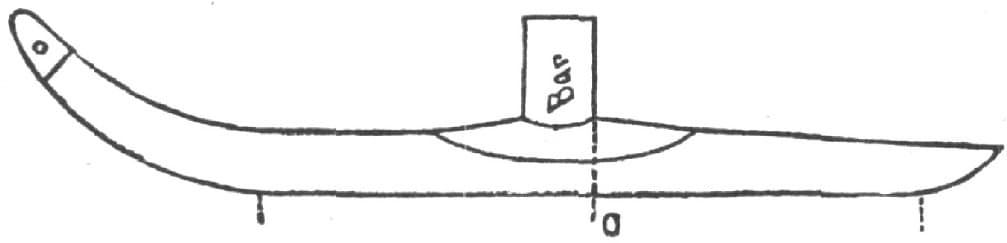
The first cause is the misplacement of the shafts. I now allude to sleighs for country roads, where the horse can only travel in the beaten track, which necessitates the setting of the shafts to one side. In cities where the snow is usually level, because of great traffic, the horse can travel immediately in front of the sleigh. In Fig. 189, A, A represent noses of the front bobs, B the shaft bar, C, C the jacks. The jacks must be placed in such a position that when the horse is attached and doing his work, the front bob will run directly forward.
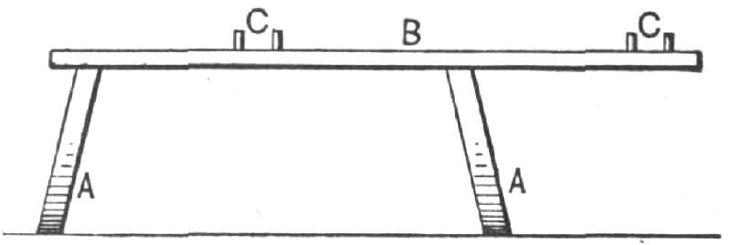
Making Bob Sleds. Fig. 189—Showing the Position of the Shaft Bar
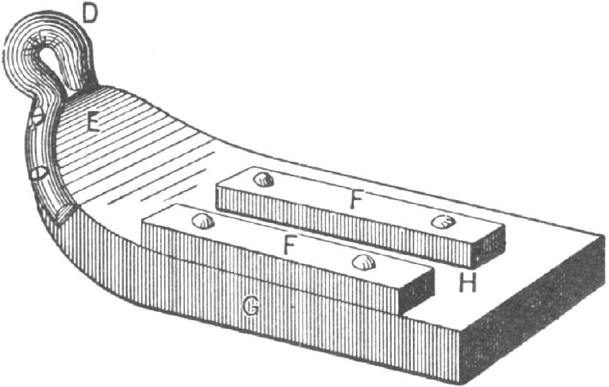
Fig. 190—Top View of the Brake
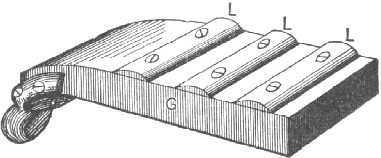
Fig. 191—Bottom View of the Brake
It will be noticed that the long end of the bar is to the right side, which is to facilitate turning out to the right side of the road when meeting teams. Were the long end, or projecting end, on the left side, a greater detour would have to be made, so that the bars might not interfere. Besides, in places where the snow is always quite deep, if the long end were not on the right side it would be next to impossible to turn out. If the jacks be placed too far to the right, it will cause the nose of the front bob to crowd to the left; if too far to the left, the nose of the front bob will crowd to the right.
To get at the right position, measure your sleigh track. Then stand two horses before your sleigh in the position they would occupy, and mark the position of the hind feet, remove the horses and place the shaft in such a position that if a plumb line be dropped from the center of the shaft bar it will touch at the center of the track, between the feet of the right-hand horse. When you once have the measurement, record it. It will last as long as you build sleighs.
I now refer the reader to Fig. 192, in which M, M represent the front of the bob, N, N the back of the bob. In putting together, have them square and prove them so, as shown by the dotted diagonal lines O, O. Fig. 194 represents the bob bottom up, and as you put on the stays, P is the bar, R, R are the posts. Prove them square by the dotted diagonal lines S, S. If you are right up to this point, and the shafts are properly placed, there will be no danger of your bobs “sliding”—moving from one side to the other—provided they are properly coupled to the body, an operation I illustrate in Figs. 195 and 196. I will begin with Fig. 196. The body must be perfectly or strictly square at all corners, or you will find much trouble in getting your bobs to run parallel. E represents the front of the body. Having found the proper position to place your front bolster F, secure the same temporarily; then measure from E to F, as per the dotted parallel lines d, d, and have the distances equal, and prove you are square by the dotted diagonal lines. When right, secure F in position permanently. Then place the back bolster G in position temporarily, and have it equi-distant at each end from F, as per dotted lines b, b, and prove correctness by dotted diagonal lines g, g, and when correct secure permanently. This finishes the fastening of the bolster to the body.
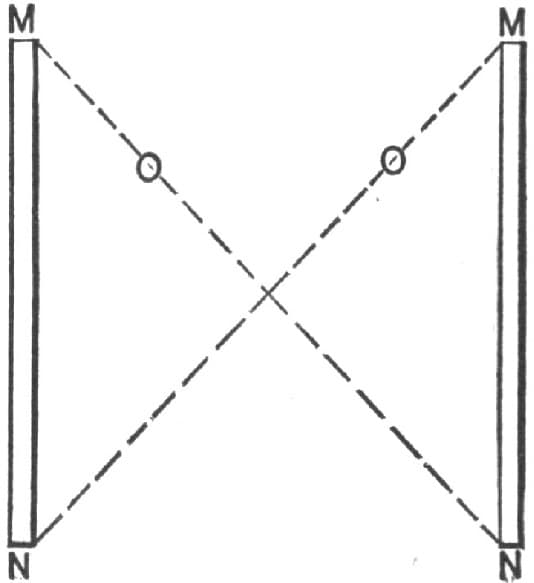
Fig. 192—Showing the Front and Back of the Bob
Fig. 193—Showing the Hoop Bolt
Fig. 194—Bottom View of the Bob
Fig. 195—Showing How the Bobs are Coupled to the Body
Fig. 196—Showing Another Stage in the Coupling Process
The next part of the programme is shown by Fig. 195. Place the body on the bolster, the bob standing on the floor. Have the bar and bolster parallel with each other, the bolster having been squared on the bob by the same process as the bars were squared on the body. Then measure from each bob on its outer side to the outer ends of the body and get the distances equal. T is the body; Y, Y are the body corners at the sides; U, U are runners. Prove as per the dotted diagonal lines X, X. If all these precautions are taken your bobs will run as straight as an arrow.
About brakes. There are a number of appliances. The best is the wide skid or shoe shown in Fig. 190, in which D represents an iron eye of the proper size, with straps on each side of the part of the shoe at the curve E, or it may be so made as to go over top and bottom. G is the body of the shoe—six inches wide, one and one-half inches thick, twelve inches or more long. The pieces F, F are eight inches long, two inches high. They are bolted fast to the shoe. The inner piece is bolted to the inner edge, and there is space enough between the two to allow the runner to enter readily. The projection is on the outside, so as to catch on the unbroken or rough snow. On the bottom, secure at equal intervals pieces of half round or half oval iron transversely, as indicated by Fig. 191. Attach a chain at the eye D, and secure the chain to the body so as to allow of the brake adjusting itself to the front of the runner, which will throw a pressure on the heel of the shoe of the back bob and thus produce friction. The great width of the braking shoe, and the fact of its projecting over the rough and unbroken snow, together with the transverse bottom bars, will be sufficient to bring any ordinarily loaded sleigh to a standstill on any ordinary hill. When hills are unusually steep two transverse pieces eight inches apart are better than three. I have found one quite sufficient. Fig. 193 is a hoop bolt on which the shoe brake is hung when not in use. The front ends of the back bob should have a chain running up to the body so as to lift the nose up when dropping into holes, but slack enough to give the bob sufficient play to suit the unevenness of the road.
In securing the back bob it should be remembered that it acts much like a ship rudder. If the nose is too much to the right it will crowd the front bob to the left, and if too much to the left, vice versa.—By IRON DOCTOR.
Hanging Bob Sleds.
In my opinion the bunk on a forward traverse should not be over two inches back of the center of the run, but the hind sled should be hung further back. If your sled is four feet on the run, I think it should be hung six inches back of the center. Some say eight inches. You will find that when sleds are hung in this way the shoes will wear very near even on the whole surface. If you get on a stone or hard ground, your sled will not stick as it would if hung in the center. And if you get into deep snow the hind sled will follow the front one very much easier than it would if it were hung nearer the center.
The reason the front and rear sleds should not be hung alike is that, as the team is hitched to the front sled, the front of the forward sled does not bear as hard on the road as the front of the hind sled would if they were hung alike. I think anyone can see that to have a sled run easy the shoes should wear even. If one does not understand the principle of hanging sleds, just take a hand sled and slide down hill three times: the first time sit over the front beam (if you don’t sit on the snow before you get to the bottom of the hill you will be lucky), the next time sit over the middle beam, and the last time sit nearly back on the hind beam. You will find that the last time down you will ride much the easiest, and your sled will go the farthest. You can see after this trial how a hind traverse would work hung forward of the center.—By W. L. P.
The Tread of a Bob Sled.
I have been in the sled-making business for ten years, and have a reputation second to none for building well-hung and easy running sleds. My rule for placing the bars is as follows:
The Tread of a Bob Sled. Fig. 197—The Front Bob
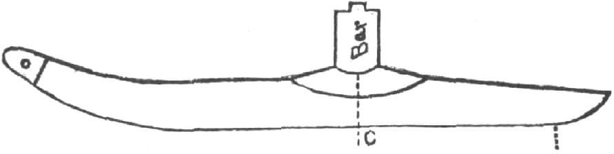
Fig. 198—The Rear Bob
I find the center of tread by applying the straight-edge to the runner, then place the front bar forward of the center, as shown in Fig. 197, and place the hind bar on the center, as in Fig. 198. I generally use the Bartlett patent. It makes the strongest and easiest running sled in the world.—By G. W. R.
A Brake for a Bob Sled.
In making a sleigh brake, I get the width from outside to outside of the raves of the rear bob, next take a piece of one and one-fourth inch round iron, six inches longer than the sled, and then jump on a piece of 11/2 × 5/8 inch, six inches long, as at E, Fig. 199, with a hole half an inch from the end. Next I weld a collar on, A, to keep the brake in place when on the sled; then make a two-eyed bolt to fasten the brake to the rave. This I slip on A, and jump on a piece of 11/2 × 5/8 inch, outside of the rave at B; then I draw the bar down to a square for the lever, and put on a nut having a thread to hold the lever D in place. Next, I make the brake hands F of a piece of common steel, 2 × 1/2 inch. The wider the digging points are made, the better they will hold. Then I bolt A to the sled over the center of the rave, then bolt the hands on the runner so that the points will strike the center of the rave as near as possible. The brake can be adjusted to suit. The straps G are made of 1 × 1/4 inch tire iron. Fig. 200 shows the job completed. This brake is operated with a rope as the driver sits on top of his load. When he pulls, the hands dig, and when he lets go, the load carries the hands up out of the way. This brake will never fail.—By E. H. A.
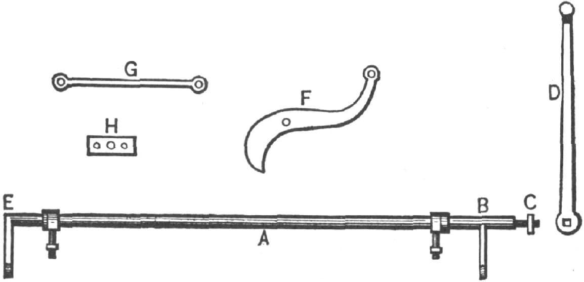
A Brake for a Bob Sled, as Made by “E. H. A.” Fig. 199—Showing the Parts in Detail
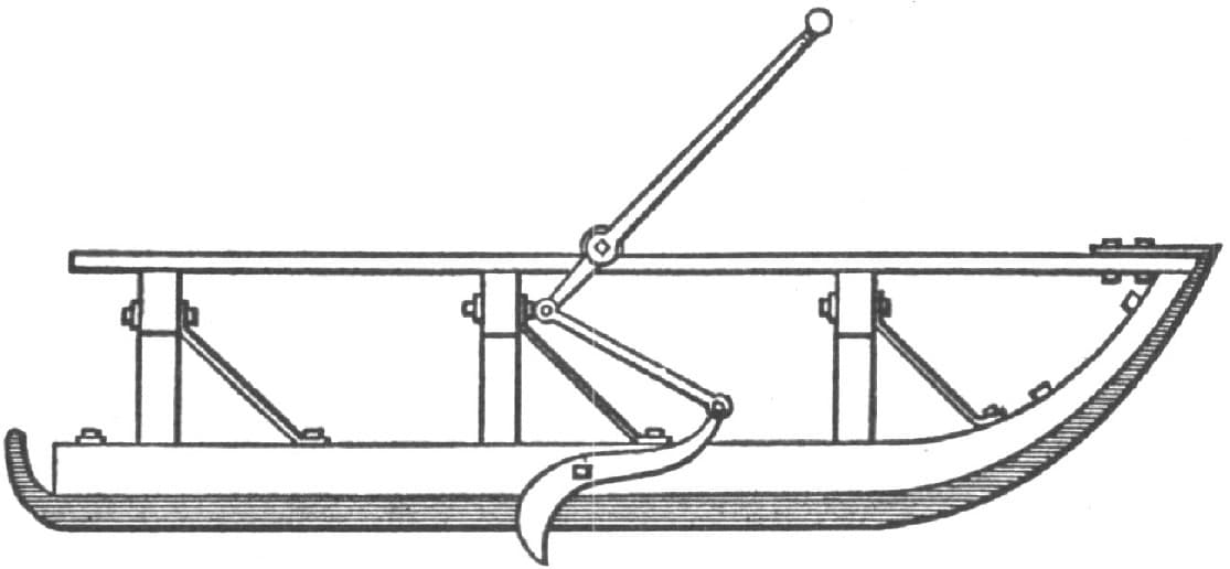
Fig. 200—Showing the Brake in Position
An Improved Sled Brake.
I make a self-acting break for a sled that is very simple and effective, as follows: A, Fig. 201, is a movable nose of the same size as the runner, to which it is bolted at G. It may extend above the runner, as shown, if desirable. D is the brake, swinging on the pin at E. C is a rod connecting the brake with the lower end of the movable nose. When the load presses upon the team, the movable nose, turning on the pin G, acts upon the break, as indicated by dotted lines. Any simple device may be used for confining this nose to the runner at B when the brake is not in use.—By E.
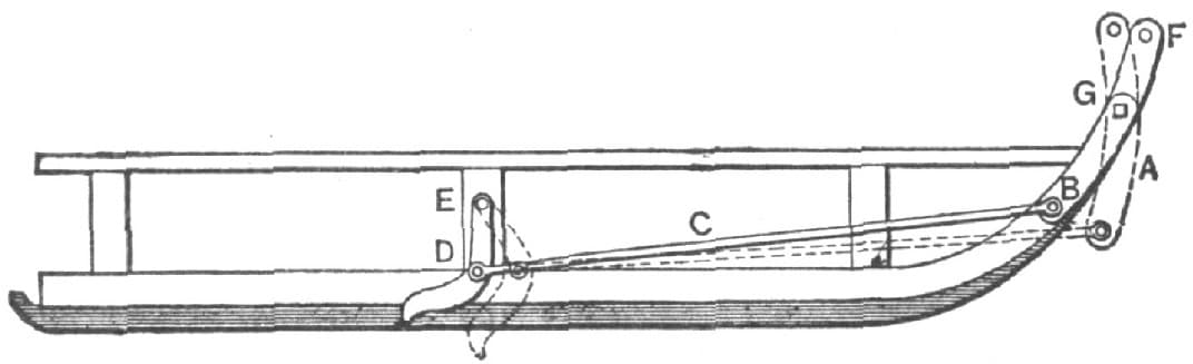
Fig. 201—An Improved Sled Brake, as Made by “E”
Fitting Sleigh Shoes.
The quickest and best way that I know of fitting sleigh shoes is to heat them evenly as far back from the end as they are to be bent. Have a strip of tin the width of the runner and long enough to cover the whole bend of the runner as far as the iron is heated. Place this strip on the runner, and fasten it, if necessary, with a small brad. Have at hand a pair of tongs large enough to take in the runner and the end of the shoe. Let a helper hold these together with the tongs while you bend down the shoe, hammer slightly, if necessary, and you have a perfect fit without burning the runner. If you have no help, the end of the shoe can be held to the runner with a clamp.—ANONYMOUS.
Centering Bob Sleds.
I have made and ironed a great many traverse runners, and my way is this: After the hind end is clipped for backing I take the length of bearing, plus four inches on the forward end, and place the center of the bunk on the center of this measurement, placing both bunks alike. The plan gives general satisfaction.—By S. F. G.
Plating Sleigh Shoes.
I am an ironworker, and would like to say for the benefit of blacksmiths and others that one of the best ways to plate sleigh shoes is to use one-eighth Norway iron, one-half inch wider or more than the steel to be plated; lay the steel in the center of the iron, heat and form round the steel, Fig. 202, S representing steel and I iron. Form as you weld. Shoes plated by this method can be made lighter and stronger, and in case they spring when hardening can be bent in any direction without cracking.—By D. F.
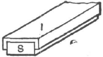
Fig. 202—Plating Sleigh Shoes
Hanging Traverse Runners.
My plan of hanging traverse runners is to hang them from two to six inches back of the center, measuring from the shoe where it strikes the floor. If the rear bob draws from the top it may be hung a little farther back than the front one. The longer the knees are, the farther back they should be hung to run well. By looking at the shoes of some that are almost worn out, anyone can generally judge where to hang them. I think that twenty-four pairs out of twenty-five are hung too far forward for the good of the team obliged to draw them. If the shoe is all worn out on the nose, and as thick as when new at the heel, it shows that there is something rotten in the state of Denmark.—By G. W. B.