CHAPTER VII
PROPORTIONS OF BOLTS AND NUTS, FORMS OF HEADS, ETC
Bolts and Nuts.
Bolts are usually designated for measurement by their diameters at the top of the thread, and by their lengths measured from the inner side of the head to the end of the thread, so that if a nut be used, the length of the bolt, less the thickness of the nut and washer (if the latter be used), is the thickness of work the bolt will hold. If the thread be within the work and no nut, therefore, be necessary, the same rule as to length holds good, because the depth of the thread in the work is equivalent to the nut; hence the thickness of work that a bolt will hold is equal to the length of the bolt from the inside of the bolt head to the inner radial face of the nut when the latter is screwed upon the bolt, so that the end of the bolt has emerged to the distance that the end is rounded or chamfered off. It is assumed in this case that the end of the bolt passes or screws into the work to a depth equal to the depth of a nut which should equal the diameter of the bolt.
A black bolt is one left as forged. A finished bolt has its body, and usually its head also, machine finished, but a finished bolt sometimes has a black head.
A square-headed bolt usually has a square nut, but if the nut is in a situation difficult of access for the wrench, or where the head of the bolt is entirely out of sight; as beneath a secluded flange, the nut is often made hexagon. A machine-finished bolt usually has a machine-finished and hexagon nut. Square nuts are usually left black.
The heads of bolts are designated by their shapes, irrespective of whether they are left black or finished.

Fig. 203—Various Forms of Heads
Fig. 203 represents the various forms; a, square head; b, hexagon head; c, capstan head; d, cheese head; e, snap head; f, oval head, or button head; g, conical head; h, pan head; i, countersink head.
Bolts are designated as in Fig. 204, in which k is a machine bolt, l is a collar bolt, m is a cotter bolt, n is a carriage bolt, and o is a tire bolt.

Fig. 204—Designations of Bolts
In Fig. 207, s is a patch bolt, t, u, v are plow bolts, and w is an elevator bolt.
A tap bolt is one which screws into the work instead of requiring a nut. The distance its thread enters the work should be at least equal to the diameter of the thread, and in cast-iron about one and a quarter to one and a third times the diameter, on account of the difference in strength of the thread on the wrought-iron bolt and the cast-iron thread in the hole. Tap bolts have usually hexagon heads, and are left either finished or black, as circumstances may require.
A stud or standing bolt is formed as in Fig. 205. The threaded part A is to screw a tight fit into the work, the stud remaining firmly fixed. The plain part B is intended to enter the work, the bore of the thread in the hole having the thread cut out to receive it. By this means the shoulder between B and C will abut against the face of the work, and the stud ends E will all protrude an equal distance through the nuts, providing, of course, that the thickness of the flange bolted up, and also of the nuts, are all equal. Another method of accomplishing this result is to cut a groove where B joins C, a groove close up to the shoulder, and extending to the bottom of the thread, so that the thread may terminate in the groove. By this means the shoulder will screw fairly home against the face of the work, while the plain part B is dispensed with, and clearing out the thread at the entrance of the hole becomes unnecessary. The part B extends nearly through the hole in the flange to be bolted up, and the fit of the thread at D is made to screw up a good working fit under hard pressure.

Fig. 205

Fig. 206
In some practice the part C is made square, so that a wrench may be applied to extract the stud when necessary.
A set screw is formed as in Fig. 206, the diameter of the head being reduced because the working strain falls upon the thread, and the head is used to merely screw the set screw home. Set screws are employed to enveloped pieces, as in securing hubs to shafts the enveloping piece is threaded to receive the screw whose end, as the set screw is screwed home, is forced against the piece or shaft enveloped. This end pressure is apt to cause the end of the screw to spread, rendering it difficult to unslack or screw back the screw. To avoid this the following methods are resorted to:
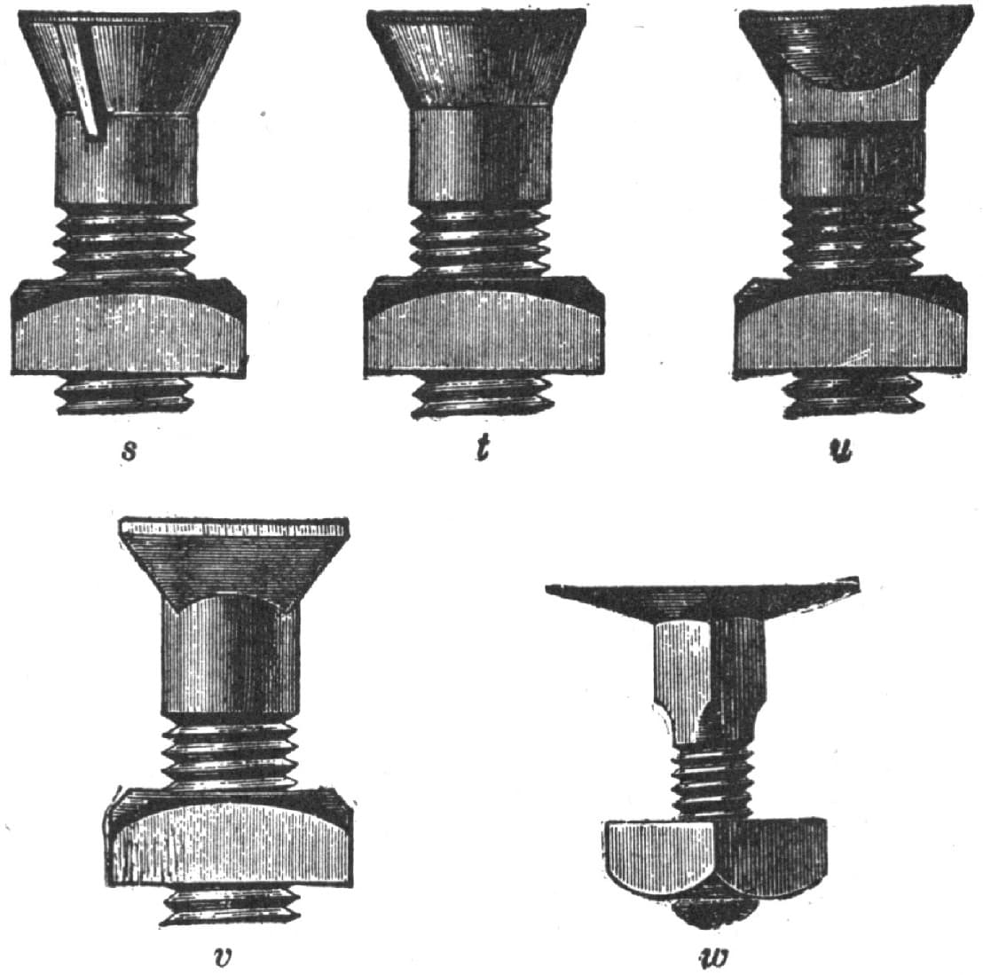
Fig. 207. Designations of Bolts
Sometimes the end is rounded, so that the pressure falls on the middle or center of the screw only, but as this reduces the area of contact, increases the liability to spread, and allows the screw to become loose, a cup recess of about half the diameter of the screw is provided. A better plan is to chamfer off the end of the thread for a distance of about two threads, or the thread may be turned off the end of the screw for the same distance. A still better plan is to cup the end of the set screw, as shown in Fig. 204, so that the screw end will compress a ring in the shaft. Set screws should be of steel, with the points, at least, hardened, which enables them to grip the shaft more firmly, and obviates the spreading. But if made of wrought iron, they or their ends should be case-hardened.
The term cap screw is applied to the screws made especially for the caps of journal boxes or bearings. They have square or hexagon heads, and are usually machine-finished all over. The part beneath the head is left cylindrical for a distance varying according to order, but usually nearly equal to the diameter of the screw, the thickness of the flange of the cap usually equaling that diameter.
Machine screws are designated for diameter by the Birmingham wire gauge, and have their thread pitches coarser than those on standard bolts and nuts.—By J. R.
Bolts and Nuts and Their Threads.
Up to the year 1868 there was no United States standard for the sizes of bolt heads or nuts, or standard pitches of screw threads for bolts. As a result, threads were made of different forms and pitches by different makers. In 1868, however, William Sellers & Co., of Philadelphia, designed an angle and pitch of thread, and a standard size of bolt head and nuts, which was recommended for adoption as the United States standard by the Franklin Institute, and subsequently, with a slight modification in the sizes of bolt heads and nuts, adopted by the United States Navy Department as a standard, which is now known as the United States standard. At the present time the matter stands thus:
There are three forms of thread in use in the United States. The first is shown in Fig. 208. It is known as the V thread, or sharp V thread, its sides being at an angle of sixty degrees. This thread is in more common use than any other, being the standard for gas and steam pipes, and is in very general use.

Fig. 208

Fig. 209
The second is that referred to above as the United States standard thread, its form being as in Fig. 209. The sides are at an angle of sixty degrees. The depth of the thread is divided off into eight equal divisions. The top and bottom division is taken off, so as to leave a flat place at both top and bottom. The application of this thread is continually increasing, prominent toolmakers keeping tools and dies in stock for cutting it, recommending its use and doing all in their power to further its universal adoption.

Fig. 210
The third form, Fig. 210, is the English, or Whitworth thread, which is adopted by some of the prominent bolt makers, by some influential private firms, as R. Hoe & Co., of New York, and by some railroads. The sides of the thread are at an angle of fifty-five degrees, the depth of the thread is divided off into six equal parts, and with a radius of one of these parts a circle is described, cutting off one of the parts at the top and at the bottom, and giving to the top and bottom a rounded form.
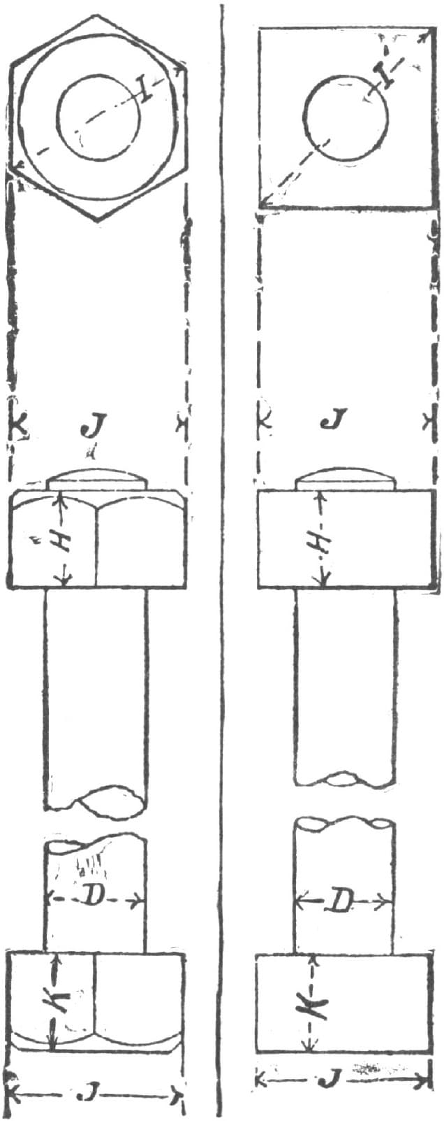
Fig. 211
The foregoing table, in conjunction with Fig. 211, explains the United States standard sizes for bolts and nuts and the pitches of the threads.
United States Standard Dimensions of Bolts and Nuts.
| BOLT. | ||
| Diameter. | Standard number of threads per inch. | |
| Nominal. D. | Effective. * | |
| 1/4 | .185 | 20 |
| 5/16 | .240 | 18 |
| 3/8 | .294 | 16 |
| 7/16 | .345 | 14 |
| 1/2 | .400 | 13 |
| 9/16 | .454 | 12 |
| 5/8 | .507 | 11 |
| 3/4 | .620 | 10 |
| 7/8 | .731 | 9 |
| 1 | .837 | 8 |
| 1 1/8 | .940 | 7 |
| 1 1/4 | 1.065 | 7 |
| 1 3/8 | 1.160 | 6 |
| 1 1/2 | 1.284 | 6 |
| 1 5/8 | 1.389 | 5 1/2 |
| 1 3/4 | 1.491 | 5 |
| 1 7/8 | 1.616 | 5 |
| 2 | 1.712 | 4 1/2 |
| 2 1/4 | 1.962 | 4 1/2 |
| 2 1/2 | 2.176 | 4 |
| 2 3/4 | 2.426 | 4 |
| 3 | 2.629 | 3 1/2 |
| 3 1/4 | 2.879 | 3 1/2 |
| 3 1/2 | 3.100 | 3 1/4 |
| 3 3/4 | 3.317 | 3 |
| . . | 3.567 | 3 |
| 4 1/4 | 3.798 | 2 7/8 |
| 4 1/2 | 4.028 | 2 3/4 |
| 4 3/4 | 4.256 | 2 5/8 |
| 5 | 4.480 | 2 1/2 |
| 5 1/4 | 4.730 | 2 1/2 |
| 5 1/2 | 4.953 | 2 3/8 |
| 5 3/4 | 5.203 | 2 3/8 |
| 6 | 5.423 | 2 1/4 |
| BOLT HEAD AND NUT. | ||
| Long diameter, I, or diameter across corners. | Short diameter of hexagon and square, or width across J. | |
| Hexagon. | Sqaure. | |
| 9/16 | 23/32 | 1/2 |
| 11/16 | 27/32 | 19/32 |
| 25/32 | 31/32 | 11/16 |
| 29/32 | 1 3/32 | 25/32 |
| 1 | 1 1/4 | 7/8 |
| 1 1/8 | 1 3/8 | 31/32 |
| 1 7/32 | 1 1/2 | 1 1/16 |
| 1 7/16 | 1 3/4 | 1 1/4 |
| 1 21/32 | 2 1/32 | 1 7/16 |
| 1 7/8 | 2 5/16 | 1 5/8 |
| 2 3/32 | 2 9/16 | 1 13/16 |
| 2 5/16 | 2 27/32 | 2 |
| 2 17/32 | 3 3/32 | 2 3/16 |
| 2 3/4 | 3 11/32 | 2 3/8 |
| 2 21/32 | 3 5/8 | 2 9/16 |
| 3 3/16 | 3 7/8 | 2 3/4 |
| 3 13/32 | 4 5/32 | 2 15/16 |
| 3 19/32 | 4 13/32 | 3 1/8 |
| 4 1/32 | 4 15/16 | 3 1/2 |
| 4 15/32 | 5 15/32 | 3 7/8 |
| 4 29/32 | 6 | 4 1/4 |
| 5 11/32 | 6 17/32 | 4 5/8 |
| 5 25/32 | 7 1/16 | 5 |
| 6 7/32 | 7 19/32 | 5 3/8 |
| 6 5/8 | 8 1/8 | 5 3/4 |
| 7 1/16 | 8 21/32 | 6 1/8 |
| 7 1/2 | 9 3/16 | 6 1/2 |
| 7 15/16 | 9 23/32 | 6 7/8 |
| 8 3/8 | 10 1/4 | 7 1/4 |
| 8 13/16 | 10 25/32 | 7 5/8 |
| 9 1/4 | 11 5/16 | 8 |
| 9 11/16 | 11 27/32 | 8 3/8 |
| 10 3/32 | 12 3/8 | 9 3/4 |
| 10 17/32 | 12 29/32 | 9 1/8 |
| Depth of nut, H. | Depth of bolt head, K. | |
| 1/4 | 1/4 | |
| 5/16 | 19/64 | |
| 3/8 | 11/32 | |
| 7/16 | 25/64 | |
| 1/2 | 7/16 | |
| 9/16 | 31/64 | |
| 5/8 | 17/32 | |
| 3/4 | 5/8 | |
| 7/8 | 23/32 | |
| 1 | 13/16 | |
| 1 1/8 | 29/32 | |
| 1 1/4 | 1 | |
| 1 3/8 | 1 3/32 | |
| 1 1/2 | 1 3/16 | |
| 1 5/8 | 1 9/32 | |
| 1 3/4 | 1 3/8 | |
| 1 7/8 | 1 15/32 | |
| 2 | 1 9/16 | |
| 2 1/4 | 1 3/4 | |
| 2 1/2 | 1 15/16 | |
| 2 3/4 | 2 1/8 | |
| 3 | 2 5/16 | |
| 3 1/4 | 2 1/2 | |
| 3 1/2 | 2 11/16 | |
| 3 3/4 | 2 7/8 | |
| 4 | 3 1/16 | |
| 4 1/4 | 3 1/4 | |
| 4 1/2 | 3 7/16 | |
| 4 3/4 | 3 5/8 | |
| 5 | 3 13/16 | |
| 5 1/4 | 4 | |
| 5 1/2 | 4 3/16 | |
| 5 3/4 | 4 3/8 | |
| 6 | 4 9/16 | |
* Diameter at the root of the thread.
Turning Up Bolts.
I want to give you a couple of hints that will be found quite acceptable in country shops where bolts are turned up. The first is to use a dog, fastened to the face plate as in Fig. 212 of the accompanying engravings. This saves screwing and unscrewing a loose dog every time. The second is to bend all cutting-off and facing tools as in Fig. 213, so that they will well clear the dog.
These points may not be new to some, but I think they will be found as useful to others as they were to me.—By F. J. L.
Sizes of Bolt Heads.
In determining the sizes of bolt heads we have the following to consider: So far as convenience in the use of the bolts is concerned, it is desirable to have the diameter across the flats of the heads the same for those left black as forged, as for those machine-finished, so that one solid wrench will fit all the heads, whether black or finished, of a given diameter of bolt. But in this case bolts that are to have their heads machine-finished must be forged larger, to allow for the metal cut away in finishing the same.
Hence, if all bolt heads for a given diameter of bolt were forged to the size necessary to allow for this finishing, those not finished will be larger than those finished, and two sizes of solid wrenches will be necessary for each diameter of bolt.
To obviate this difficulty it is necessary to forge the heads of black bolts to the same size as that for finished bolts, which will save iron, enable the use of one size of wrench for black and finished, and involve no trouble other than that of specifying in ordering bolts whether the heads are to be left black or finished. It is unfortunate, as leading to confusion, that there is no uniformity of practice in this respect. Thus in the “Sellers” or “Franklin” Institute system the rule is as follows: “The distance between the parallel sides of a bolt head and nut for a rough bolt shall be equal to one and a half diameters of the bolt, plus one-eighth of an inch. The thickness of the head for a rough bolt shall be equal to one-half the distance between its parallel sides. The thickness of the nut shall be equal to the diameter of the bolt. The thickness of the head for a finished bolt shall be equal to the thickness of the nut. The distance between the parallel sides of a bolt head and nut, and the thickness of the nut, shall be one-sixteenth of an inch less for finished work than for rough.”
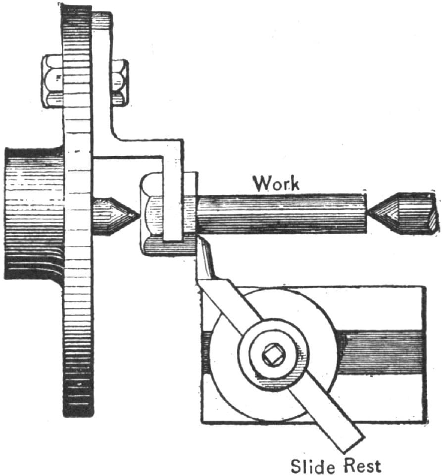
Turning Up Bolts by the Method of “F. J. L.” Fig. 212—Showing the Dog Fastened to the Face Plate
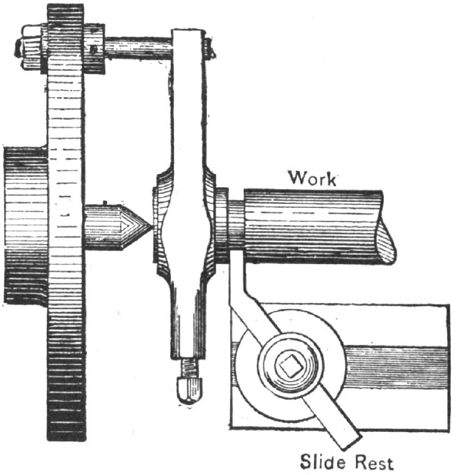
Fig. 213—Showing the Method of Bending and Facing the Cut-Off Tools
The United States Navy Department, which adopted this Sellers system so far as the pitches, angles, shape of bolt thread and diameter of finished bolt heads is concerned, varied from it by adopting the system of making the standard for black or rough bolt heads of the same size as those for finished heads, and this is undoubtedly the most convenient for use.—By R. J.
An Apparatus for Making Rings.
A simple and convenient apparatus for making small rings in lots can be made of two and one-half inch gas pipe, as shown at A in Fig. 214, with a slot at F, a collar at G. A hole is made in the bench at B, Fig. 215, to admit the end of the pipe. A post E, with a slot large enough to admit the pipe, is placed just outside the collar G, and a brace C is nailed on the post and bench to hold the pipe against the bench. A pin D is put through the post above the pipe to prevent it being lifted out while in operation.
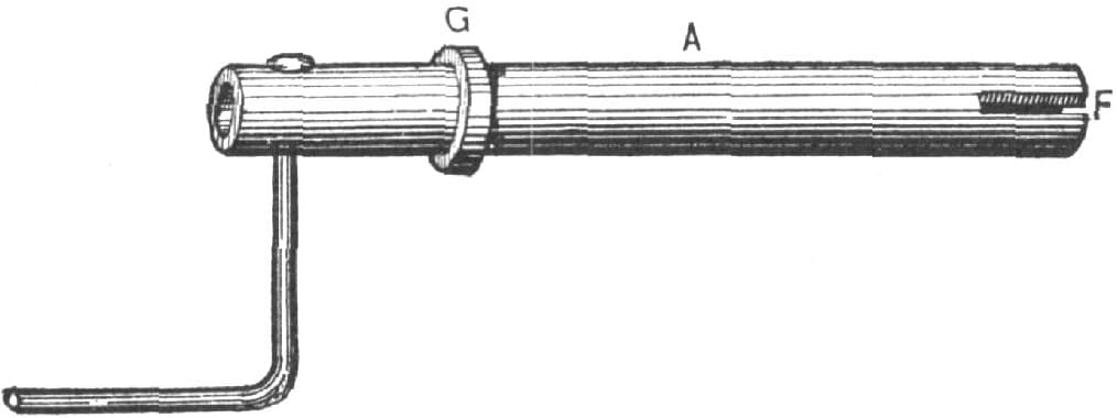
An Apparatus for Making Rings. Fig. 214—Showing the Pipe Used
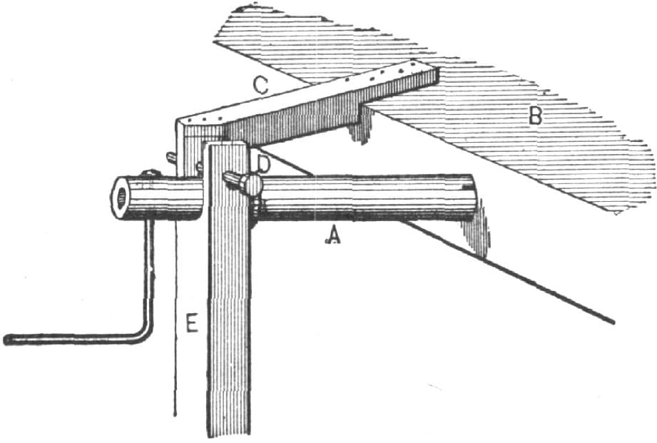
Fig. 215—Showing the Apparatus Ready for Use
To use the apparatus proceed as follows: Heat one end of the bar and loosen it down about one inch, forming a hook, place the hook in the slot F, let one man turn the crank while another leans on the bar near the pipe. The bar is wound into a coil, which can be taken off the pipe by withdrawing the pin D and lifting out the pipe. Place the coil diagonally across the point of your shears, and every clip will give you a ring. The rings can be made larger or smaller by cutting them with the gap more or less open. They will be cut scarfed ready for welding, and a few light blows will bring the nicks together. One heat alone is enough to weld and finish up.
To Make Rings Without a Weld.
Steel rings without a weld have become a staple article of manufacture.
One method of making these rings may be described by taking as an illustration a ring twelve inches in diameter, two and one-half inches wide across the face and one and one-eighth inches thick. This will answer all purposes for description, for although, if it were to be a milling cutter, the thickness would, of course, be much greater in proportion to the width of face, yet the operations in forging would be the same.
In making this ring from the solid stock we propose to take a piece of suitable size and length, punch a hole in each end, split the piece from hole to hole, open out the split, and hammer up the sides and ends, until the stock in the ring is of the right size and shape, and the diameter is that which is required. A representation of this bar, after the ends are punched, is given in Fig. 216.

Fig. 216—Showing the First Steps in the Making of Solid Steel Rings
The piece is then “upset” on each end enough to make it half an inch thicker, for two and one-half inches back; the holes are punched, either with a five-eighths inch pear-shaped, or a rough punch, one and three-eighths inch from the ends, and the corners are then cut.
The next thing to be done is to split it, which is done by marking it through the center with a straight line when it is cold enough to use a cold chisel, and then heating it and cutting half way through on each side. The more nicely this is done, the less trouble it will be to work the sides. A good, but not a regular heat is then taken all over, to open it. If the ends are much longer than the sides are thick they give unnecessary trouble in opening. In this case they should not exceed one and one-eighth inches. All that is wanted of the length is to get stock to fill up the lankness caused by changing the punched circle of five-eighths of an inch to the full circle of the ring. When it is opened out to the shape shown in Fig. 217 by driving larger pins into it successively over holes in the swage block, it can be got on the horn of the anvil, and a ten-pound sledge brought to bear to knock out the short crooks, which are liable to get in if the piece does not have just the right kind of a heat on it, when it is opened out. If it is properly heated, which will be when it is the hottest at each extreme end, it can be made to open out as shown in Fig. 218. There will be much less trouble in finishing a piece which is thus opened.
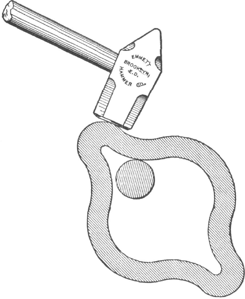
Fig. 217—Showing the Method of Knocking Short Crooks Out of a Ring
There will be a tendency to upset and get smaller if the ring is hammered on the outside with too light a sledge, while neither heavy nor light blows, if struck with a heavy sledge, will tend so much to produce this effect. It is desirable to have a solid mandrel of the proper size on which to round the ring, and this is especially necessary when it comes to the last and finishing heat. A furnace should also be provided for heating which will heat it uniformly in the finishing up process; for if one side is cold, it is not easy to stretch the other side against the pressure it bears. In hammering on a solid mandrel, the taper takes up the stretch and hinders the tendency to upset, which, if not counteracted, causes time to be lost and blows spent without accomplishing what they should.—By B. F. SPALDING.
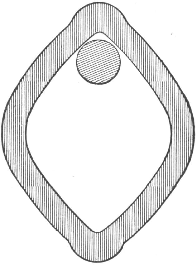
Fig. 218—Showing How the Ring is Bent to Avoid Short Crooks
How I Made a Cast-Steel Cylinder Ring.
The ring when finished was of the following dimensions: diameter, seven inches; width, one and three-eighths inch; thickness, one-fourth of an inch. The only steel I had was a piece of one and three-fourths inch square. I first split about five inches, then opened it with mandrels until I could get it on the horn of the anvil. I next drew the end until I got it round, and then drew it to the proper size. It was nearly two inches wide when finished, and that gave plenty of room to chuck in the lathe. I next turned it to its proper size, and had yet to cut the slot and to cut the steel in two as shown at the dotted lines Fig. 219. I first drilled two one-fourth inch holes as at A, and then with a hack saw I cut from one hole to the other, first filing down one side. To get the saw blade in after finishing the slot I cut across as shown at the dotted lines B. I sprung it to place carefully without tempering and found it had enough spring to come back to its original position.—By DOT.
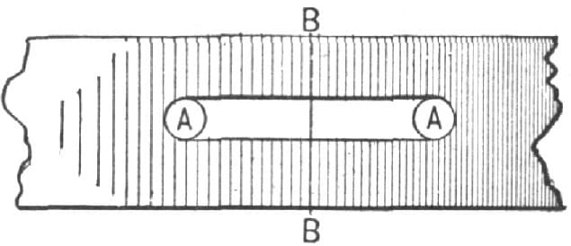
Fig. 219—Making a Cast-Steel Cylinder Ring by the Method of “Dot”
A Device for Making Rings.
The accompanying illustration, Fig. 220, represents a device of mine for making a ring the exact size of any I already have. I measure from one center of the iron to the opposite outside as shown in the cut, and multiply this measurement by three. This will give the length to cut the iron, and the same rule is good for all sizes.—By A. L. D.
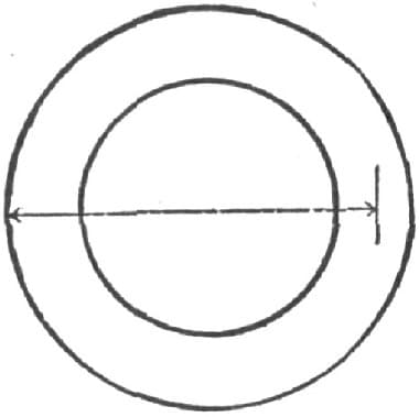
Fig. 220—“A. L. D.’s” Device for Making Rings to Measure