Understanding the features, functions, and installation of power supplies
Identifying features and functions of AC adapters
This chapter takes a look at two main items: power supply units (PSU) and uninterruptible power supplies (UPS). Power supplies should actually be called power converters because the largest single function they perform is a conversion of power from 120 volt (V) or 240V to something that can be used by the computer system.
As a CompTIA A+ Certified Professional, you will at least have to add a component to a computer that requires power from the power supply (such as a hard drive), and you will also probably be required to troubleshoot and replace a power supply in the computer system. The information in this chapter gives you all the technical specifications and connector types you will need to know about a power supply. Together with the troubleshooting chapter (Book 4, Chapter 2), you will have all the information that you need to know about power supplies.
Knowing the Basics of Power Terminology
You should learn four terms that deal with power in computer systems: volts, ohms, amps, and watts. If you have a firm grasp on how they relate to each other, you can understand how power is measured and used within computer systems. Electrical current flows with the same principles that are used when water flows, so water is often used as an analogy for electrical current.
Volt
A technical definition of a volt is a unit of electrical potential difference or the potential difference across a conductor when a current of one ampere dissipates one watt of power. In water terminology, voltage is represented by the pressure that is the water supply tank. This is a potential because unless you provide an exit path for water to leave the tank, this potential is not realized. If you increase the pressure in the tank, you increase the potential to supply water or power.
Ohm
An ohm is a measure of resistance or electrical impedance. When comparing electricity with water, resistance is determined by the size or diameter of the hose or pipe that is used to supply water, where a smaller hose produces more resistance.
Amp
An ampere (amp) is a unit of electric current or the measure of electrical flow. When referring to water, it is also the rate of water flow. There is a direct relationship between volts, resistance, and current: If you reduce resistance or increase voltage, you increase the current. This relationship — Ohm’s Law — is represented by this formula:
I = V / R
where I is current (amps), V is voltage (volts), and R is resistance (ohms).
Watt
The technical definition of a watt is that it is a unit of power, equal to one joule per second. If you equate this to water again, watts have you use flowing water do something. If this water runs over a waterwheel, watts are the measure of how fast the wheel can be turned by the water. If you increase the current, the wheel is able to turn faster. The formula to calculate watts is
P = V * I
where P is power (watts), V is voltage (volts), and I is current (amps).
In general, when you are working with computer systems, you will be concerned with the voltage supplied by the outlet that you connect your equipment to, the current that your equipment draws from the outlet, and the power that is used by devices that are connected to the computer power supply.
Identifying the Purpose of Power Supply Units
Remember the tasks and specifications listed in this section.
A computer’s power supply is responsible for several tasks. The following list contains typical tasks and specifications related to power supplies:
Conversion of voltage from the building-supplied AC voltage to various DC voltages used by components inside the computer.
DC voltage regulation to provide a very small tolerance of error to the devices receiving the power. Typically, a +/–5% voltage differential is allowed through the specification for 12VDC, 5VDC, and 3.3VDC connections.
Over-current protection (OCP) specifies that the power supply should handle some level of abnormally high current to prevent fuses in the power supply from blowing unnecessarily.
Input-under voltage specifies that if the voltage being supplied by the building drops below the normal operating level, it should not cause damage to the power supply itself. It will, however, likely cause your computer to turn off. For a 120V power supply, this low voltage level is usually 100V, so at voltages below that level, the power supply will simply turn off.
Energy Star is a specification that defines how much power the power supply should provide to the computer components during reduced power states, such as when the computer is put to sleep or on standby.
The PS_ON# feature allows the motherboard to control the power supply through a soft power switch. Power supplies for ATX motherboards do not use a physical switch like your light switch, which allows a circuit to be open or closed (a hard power switch). Rather, your computer’s power button is connected to the motherboard; when you press the button, the motherboard determines what action will be taken (a soft power switch). The power supply allows the motherboard to control the power state through the PS_ON# feature. The previous generation of power supplies — AT power supplies — used a hard power switch.
The power supply specification might recommend or require the use of cooling fans, depending on the form factor of the power supply.
Input supply voltage (120V or 240V) might be static or configured via manual switching or automatic switching. Many laptops have automatic switching, and most desktop power supplies have manual switching.
If you do not see a manual switch on your power supply, read the input voltage range displayed on a label on the power supply. For desktop power supplies, this label is usually found in an inconvenient location on the power supply, and you will likely need to remove the power supply from the case to read the label. In the case of laptop power supplies, even though it might have a switch, you must read the label to ensure that it does support both 120V and 240V.
Automatic switching just means that the power supply will detect and use the voltage setting for the power that is supplied. These automatic switching power supplies are also referred to as dual voltage power supplies. As I discuss at the start of this chapter, if you increase the voltage, you increase the current. Thus, the power supply not only increases the voltage but also reduces the current inside the power supply, which allows internal devices to have a consistent power level.
Identifying Power Supplies
The most common type of motherboard that you will have to provide power to will be some form factor of the ATX family (see Book 2, Chapter 1) — and, because of that, some form of power supply compatible with an ATX motherboard will be required. In the following sections, I discuss the things that are common to all power supplies that are compatible with ATX motherboards. I also take a look at the different form factors for power supplies so that the many sizes and shapes of computer cases can be supported, from tower to small form factor (SFF) to slimline cases, and all sizes in between.
When the name ATX power supply is used properly, it refers to a power supply that provides power to an ATX motherboard, and it has very specific size characteristics. Many other power supplies (such as CFX, LFX, SFX, and TFX) have different size characteristics, but all provide power to the ATX family of motherboards. Each size and shape of power supply has its own specification. In this chapter, I talk only about power supplies that provide power to ATX motherboards, regardless of their size and shape. All these power supplies use the ATX-compatible main power connector, which makes them different from the older AT power supply used with older generations of motherboards.
To find out more about the specifications for power supplies for ATX motherboards, look at the Power Supply Design Guide for Desktop Platform Form Factors document at www.formfactors.org (Search for Power Supply or locate it in the Specifications and Guides section). This Intel-operated site has specifications for many of the standard form factors used for computers and components.
The ATX power supply has undergone some basic changes in power that is supplied and in the format of the connectors. The current version of the ATX specification is 2.3. The biggest difference between the version 1.3 ATX specification and the 2.x ATX specifications is the use of a 24-pin main power connector used in the 2.x ATX specification, rather than a 20-pin connector under the 1.3 ATX specification.
With ATX power supplies having the same types of power connectors, one big difference between the power supplies you could purchase is how much power they provide to connected devices. The power supply rating refers to the total wattage that the power supply can provide to devices within your computer. Although ATX specification allows for power supplies to have ratings from 250 watts (W) up to large ones at 1200+W, most are typically around 500W to 800W. Lower wattages are available, too, but these usually follow the SFX specifications (sometimes called microATX power supplies), and these have power output down to 160W.
You may be thinking that with so many power supplies on the market to choose from, you should likely get the one with multiple rails, since that must be better, right? Not necessarily, and this has proven to be an issue of great debate. Power supplies have one or more +12V rails. A rail consists of a power circuit connected to wires supplying the standard plug connections monitored by an OCP circuit. Think of the circuits like the ones in your house, where the OCP is the circuit breaker on your power panel. In a single rail power supply, there is only a single circuit supplying power to the connected devices and a single OCP monitoring the rail for load, while multi-rail power supplies will have the total wattage supplied by several circuits, each with an OCP circuit monitoring the rail for load. For example, in my house, the kitchen may be one rail and the living room another rail. When I plug in a kettle in the kitchen and overload the rail (and trip the breaker), my television in the living room remains running. The OCP circuit keeps the whole thing from overloading, so in a multiple rail power supply, you will only lose a portion of the internal devices based on the rail they are connected to rather than all of them. But what good is your computer if only some of the components are running? Do not sweat discussions over rails; if one rail goes bad, then you are replacing the entire power supply unit.
The power supply rating required for any computer depends on the devices within the computer that need power. In most cases, bigger is better because systems that don’t have enough power for devices can experience strange, intermittent problems (see Book 4, Chapter 2). Table 6-1 provides a listing of some basic systems devices and power usage estimates as a guide to sizing up a power supply, but remember to always leave yourself some extra room.
If you are replacing a power supply in a system that experienced a failure, you can get a replacement that provides the same amount of power or more. However, if you expect that your system has more devices than the power supply can support — or if you are building a custom system — you can follow these steps:
Locate inTable 6-1any devices that your system is going to contain, then record the power usage.
Add up all the wattages and divide your total by 80 percent (0.8) to give your system some extra room to grow and to accommodate any items you might have missed.
If you did not get a number that matches an available power supply rating, choose a power supply with the next highest power rating.
To assist you in adding up the wattages used by devices, you can find a number of PSU calculators on the Internet. These will make use of standard wattage requirements for devices and will get you close to your total without the need of digging through the technical specifications for your devices.
Power Connectors
A computer uses many different types of power connectors. They include the main power, floppy, peripheral, 12 volt (+12V2DC), and serial ATA (SATA) connectors. When shopping for a power supply, you will find that there are two main categories: fixed cables and removable cables. Fixed configurations will have a variety of connectors hardwired to the power supply, while many manufacturers offer power supplies with a number of plugs along with a variety of cables, allowing you to only attach the cables which you need for the devices inside of your computer case. Typically, there is a very small price differential, and by being able to choose to only put some of the cables in your case, you improve airflow and do not have problem with what to do with a huge bundle of cables.
The ATX main power connector
On power supplies, the ATX main power connector is a 24-pin Molex 39-01-2240 connector. In many cases, it is a 20+4-pin connector for backward compatibility with older, version 1.3 motherboards. This is a keyed connector, so you cannot connect it the wrong way without a lot of effort. You can see this and other connectors in Figure 6-1.
FIGURE 6-1: Power connectors that may be used on power supplies.
Table 6-2 lists the pin configuration and voltage supply for the 24-pin Molex main power connector. When troubleshooting faulty power supplies, you need to know what power is supposed to be supplied by each pin in the power connector so that you can identify that the issue you are troubleshooting is related to a problem of power supply. To find out more about tools that can be used to diagnose issues with power supplies, refer to Book 4, Chapter 2.
TABLE 6-2 Pin Configuration for the Main Power Connector
Pin
Signal
Color
1
+3.3VDC
Orange
2
+3.3VDC
Orange
3
COM
Black
4
+5VDC
Red
5
COM
Black
6
+5VDC
Red
7
COM
Black
8
PWR_OK
Gray
9
+5VSB
Purple
10
+12V1DC
Yellow
11
+12V1DC
Yellow
12
+3.3VDC
Orange
13
+3.3VDC
Orange
14
–12VDC
Blue
15
COM
Black
16
PS_ON#
Green
17
COM
Black
18
COM
Black
19
COM
Black
20
Reserved
Varies
21
+5VDC
Red
22
+5VDC
Red
23
+5VDC
Red
24
COM
Black
The main power supply connector provides power at 3.3VDC, 5VDC, and 12VDC.
The floppy drive connector
Although floppy drives are nearly obsolete, the floppy connector is an AMP 171822-4, four-pin connector; see its pin configuration in Table 6-3. This connector provides power to a floppy drive at 5V but can supply power at either 5V or 12V to support devices from manufacturers that decide to use this connector.
TABLE 6-3 Pin Configuration for the Floppy Power Connector
Pin
Signal
Color
1
+5VDC
Red
2
COM
Black
3
COM
Black
4
+12V1DC
Yellow
The peripheral connector
Until SATA drives rule the world, the four-pin peripheral connector is likely the most used power connector on most computers because it is used for hard drives (ATA/PATA) and optical drives. This connector is an AMP 1-480424-0 or Molex 8981-04P, and its pin configuration is shown in Table 6-4. Like the floppy connector, it provides power at both 5V and 12V, but hard drives draw their power at 12V rather than the 5V sufficient for floppy drives. Hard drives require more power to get their heavier disk spinning.
TABLE 6-4 Pin Configuration for the Peripheral Power Connector
Pin
Signal
Color
1
+12VDC
Yellow
2
COM
Black
3
COM
Black
4
+5VDC
Red
The 12-volt power connector
The 12-volt power connector (+12V2DC) — also called a P4 connector — is used to supply additional power directly to the processor. It uses a Molex 39-01-2040 connector; its pin configuration is listed in Table 6-5.
TABLE 6-5 Pin Configuration for the +12V2DC Power Connector
Pin
Signal
Color
1
COM
Black
2
COM
Black
3
+12V2DC
Yellow
4
+12V2DC
Yellow
The Serial ATA connector
The Serial ATA (SATA) drive offers two more connectors to the long list that are used by computers. One connector is used for data, and the other is used for power. The data connector is discussed in Book 3, Chapter 1. The power connector uses a Molex 88751 connector, and an additional wire (5) supplies 3.3V to devices that require it. (Most functions of the SATA drive run on 12V.) The SATA connector has its five wires connected to 15 pins on the connector. The SATA connector pin configuration is listed in Table 6-6.
TABLE 6-6 Pin Configuration for the Serial ATA Power Connector
Wire
Signal
Color
1
+12VDC
Yellow
2
COM
Black
3
+5VDC
Red
4
COM
Black
5
+3.3VDC
Orange
The 6-pin PCIe connector and 8-pin PCIe connector
The 6-pin PCI Express (PCIe) connector and 8-pin PCIe connectors are used to supply additional power to energy-hungry PCIe video cards. Many cards on the market contain either a 6-pin or 8-pin connector for this purpose. The only real difference between these connectors is the amount of power they can supply. The 6-pin connector supplies an additional 75W, and the 8-pin connector supplies an additional 150W. The 6-pin connector is listed in Table 6-7, and the 8-pin connector is listed in Table 6-8.
TABLE 6-7 6-Pin Configuration for the Serial ATA Power Connector
Wire
Signal
Color
1
+12VDC
Yellow
2
+12VDC
Yellow
3
+12VDC
Yellow
4
COM
Black
5
COM
Black
6
COM
Black
TABLE 6-8 8-Pin Configuration for the Serial ATA Power Connector
Wire
Signal
Color
1
+12VDC
Yellow
2
+12VDC
Yellow
3
+12VDC
Yellow
4
COM
Black
5
COM
Black
6
COM
Black
7
COM
Black
8
COM
Black
Power Supply Form Factors
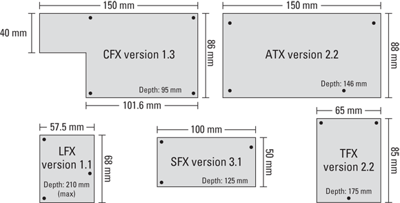
Other form factors also provide power for ATX motherboards. They exist mainly to fit in different sizes and styles of cases. These power supplies typically have the same types of power connectors that were detailed in the previous sections. The specifications for the power supplies usually define mounting points and the maximum footprint (space) that the power supply can occupy. In addition, the specifications also state whether cooling fans are required. In addition to the most common form factor — ATX v2.2 — form factors for the power supplies include the following:
CFX v1.3 is the compact form factor, typically supplying power in the range of 220W to 300W.
LFX v1.1 is the low profile form factor, typically supplying power in the range of 180W to 260W.
SFX v3.1 is the small form factor, typically supplying power in the range of 160W to 300W.
TFX v2.2 is the thin form factor, typically supplying power in the range of 180W to 300W.
The size specifications for these, as well as the ATX power supply, are shown in Figure 6-2. This figure also shows the mounting holes for each type of power supply. Computer power supplies are held in by three or four screws and are usually positioned in the top-rear portion of the computer. After removing the power connector from the internal devices, you can remove the screws and remove the power supply.
Take care when removing the screws. Some cases have rails that support the power supply; with others, the power supply could drop onto the computer components in the case when the last screw is removed. Remember, you are only removing the mounting screws for the power supply, and not the screws to access the interior of the power supply. The power supply unit is a field replaceable unit (FSU), and you should not be attempting to service the interior of the unit, which is life-threatening.
Many mainstream servers from manufacturers such as IBM, HP, and others support multiple power supplies to provide redundant support in the event of a power supply failure. These power supplies have custom connectors on the server and are typically hot-swappable — allowing them to be replaced while the server is running. As a result, these power supplies have a variety of form factors that are not covered in this book.
Using AC Adapters
Buildings run on alternating current (AC) and so do a variety of items that you connect directly to power outlets, including lamps and fans. Small electronics, such as your cellphone, do not require the amount power supplied by AC (120V or 240V) and are often designed to run on low voltage direct current (DC). The most common power source for DC devices are batteries. In order to connect a DC device to an AC power source, you need to convert or transform the AC power to the appropriate voltage DC power. The small block at the wall plug end of your cellphone charger makes this conversion for you.
Desktops have large internal power supplies to get AC building power converted to 3.3V, 5V, and 12V DC power for internal use, but laptops typically do not have the internal space to support such a large power supply. Most laptop AC adapters are external and have the job of converting the building power to a voltage that is required by the laptop. Laptops typically require between 12V and 20VDC. The laptop then has internal components that divide this incoming voltage into segments that are appropriated for the internal devices, such as 12V, 5V, and 3.3V. This allows for part of the power management components to exist outside the laptop.
In some cases, the power supply can use generic output voltages and connectors; in other cases, the voltage or connectors might be customized by a manufacturer, meaning that replacement power supplies are tied specifically to that manufacturer. The AC adapter in Figure 6-3 has a fairly standard connector. If you look closely, you can see that the output voltage is 18.5V and that input voltage is anything between 100V and 240V.
AC adapters are used with a wide variety of devices that you deal with every day, converting AC power to DC power for smartphones, cordless phones, tablets, and a host of other devices. Always take care to match the correct power adapter to the power requirements for the devices to ensure that you don’t damage the device — or worse.
When working with your AC adapter, always keep your eye out for possible damage along the length of the cord from wear or perhaps pets. Neat people actually tend to be harder on adapter cables than disorganized ones because neatniks tie up the cables every time they pack their laptops, consolidating the weight of the cable mass right next to the brick of the adapter, causing the cable to wear quickly in the section nearest the adapter. To avoid this problem, the cable should be coiled loosely and placed in your carrying case.
Working with UPS and Suppressors
Some people have such good and stable power that they take it for granted. This is not the reality for many of us, though, and we live with a variety of power issues such as these:
Spikes: Sharp increases in line voltage caused by a problem with the power utility equipment, which may be traced back to faulty transformers or lightning strikes.
Power surges: Similar to spikes, power surges are increases in line voltage that usually last longer than a spike.
Noise: Interference caused by items not directly connected to the power system. Power lines running near fluorescent lights or microwaves can have their AC sine waves altered or chopped, which affects devices receiving their power.
Blackout: A total interruption in the line power. The ATX power supply specification has a minimum voltage hold-up time of 17 milliseconds (ms), or about one-sixtieth of a second. This is how long the power supply can sustain computer operation during a power interruption. In other words, if your lights flick off and on because of a very short power outage, your computer might continue to run over that outage, but it would have to be a very brief power outage.
Brownout: The opposite of a power surge in that the line power is below normal for a period of time ranging from seconds to minutes. If the brownout exceeds the Input-Under Voltage limits of the power supply, the power supply will shut off.
Three basic devices help you deal with these power situations:
Surge suppressors: Protect your equipment against spikes and surges by quickly terminating the power connection before your equipment is damaged. These will not provide power when power is low, such as in cases of brownouts or blackouts.
Line conditioners: Take that a step further by cleaning the noise on the line and dealing with some under- and over-voltage situations, as well as generating alarms to notify you of any situations.
In most cases, line conditioners deal with surges and spikes while letting your equipment continue to function.
Uninterruptible power supplies (UPS): Take power protection beyond line conditioners by keeping your equipment working even after total power failures. This is a battery backup for your computer systems.
The two main types of UPSes are
Standby: Also called offline, a standby UPS does not protect you from surges or spikes but takes over quickly in the event of voltage drops or failures. UPS units that are marketed toward home users are usually standby units.
Inline: Also called online, an inline UPS always operates between the line and your equipment. In addition to providing power, when the UPS battery power is below a specific level, an inline UPS can initiate a graceful shutdown of the devices connected to it.
Most UPSes include scales or lights to indicate the current load on the UPS as a percentage of its maximum capacity, as well as the battery charge condition. Check these indicators regularly or install software that monitors the UPS for you. UPS indicators indicate capacity levels as well as error conditions.
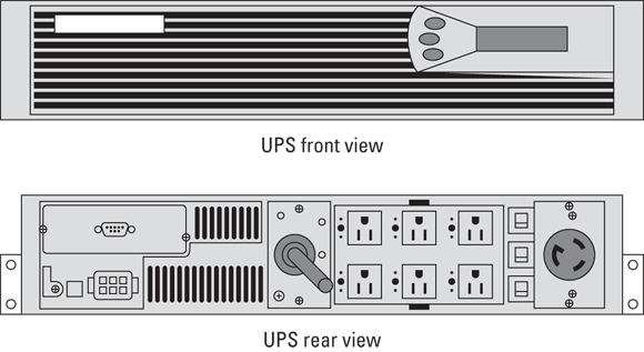
UPSes often have a variety of options for receptacle types to supply devices with power. A standard server UPS is shown in Figure 6-4. Notice the six 15-amp (NEMA 5-15R) receptacles as well as the single 20-amp twist-lock (NEMA L6-20R) receptacle. The 20-amp connector would be used to supply power to a Power Distribution Unit (PDU), which would likely have a series of standard 15-amp (IEC 320 C13) receptacles (NEMA 5-15R or IEC 320 C13; the IEC 320 C13 connector is what you find on the universal power cords used on most computing equipment).
FIGURE 6-4: Front and rear of a standard server UPS.
Most UPSes are rated in volt-amps (VA), which indicates how much power they can supply. VA ranges for UPS start around 200VA and go up to tens of thousands of VA for corporate data centers.
In a perfect world, watts and VA would be identical. Early power supplies were capacitor input power supplies that used capacitors to even out the power supplied by a building’s AC power. The method of converting power creates a variance between watts and VA of 55 percent to 75 percent, which is called the Power Factor (PF). This is represented by the formula
watts = VA * PF
Capacitor input power supplies are still in use on most inexpensive power supplies. The solution is the Power Factor Corrected (PFC) power supply, which uses watt and VA ratings that are the same. Most high-end equipment manufactured since 1996 should include a PFC power supply.
Before buying a UPS, total the power requirements for all the devices you want to plug into it, as well as the amount of time for which you need protection. The protection time is usually between 10 and 20 minutes; longer protection periods are possible if you want to pay the additional cost. Use the information to make sure you get a UPS that is powerful enough to protect all your expensive gear. You will find tools to help perform these calculations on the website for most UPS manufacturers. The tool will allow you specify information about the devices you plan to connect and the protection time you require. With this information, the tool will make a product recommendation.
Getting an A+
This chapter sheds light on power and how it interacts with your computer. The following points are covered:
The current specification of power supplies is ATX, and the ATX power supply will be found in one form factor or another on most current computers.
The main power connector has 20 or 24 pins. Four-pin floppy and peripheral connectors supply 5V and 12V, and five-pin SATA connectors supply 3.3V, 5V, and 12V.
Power supplies convert 120VAC or 240VAC power into DC power for the computer.
Power supplies come in a variety of power sizes, from 160W up to and beyond 1200W.
AC adapters are used on laptops to convert power from AC to DC, and usually automatically switch between 120V and 240V.
Surge suppressors, line conditioners, and UPS deal with various power-supply problems, including surges and brownouts.
Prep Test
1.What are the main power voltages that are provided by standard computer power supplies? (Select all that apply.)
(A) 2.1V
(B) 3.3V
(C) 5V
(D) 12V
2.What is the name given to the main type of power supply used in modern computers?
(A) AT
(B) NLX
(C) ATX
(D) WPA
3.What components influence the purchase decision of a power supply? (Select all that apply.)
(A) Hard drive
(B) Monitor
(C) RAM
(D) Parallel port scanner
4.What are the standard input voltages for power supplies? (Select all that apply.)
A, C. Both of these devices, as well as most other internal devices, affect the total power required by a power supply. Monitors have their own internal power supplies, and most parallel port scanners come with their own AC adapters. Check out “Identifying Power Supplies.”
 Remember the tasks and specifications listed in this section.
 If you do not see a manual switch on your power supply, read the input voltage range displayed on a label on the power supply. For desktop power supplies, this label is usually found in an inconvenient location on the power supply, and you will likely need to remove the power supply from the case to read the label. In the case of laptop power supplies, even though it might have a switch, you must read the label to ensure that it does support both 120V and 240V.
 When the name ATX power supply is used properly, it refers to a power supply that provides power to an ATX motherboard, and it has very specific size characteristics. Many other power supplies (such as CFX, LFX, SFX, and TFX) have different size characteristics, but all provide power to the ATX family of motherboards. Each size and shape of power supply has its own specification. In this chapter, I talk only about power supplies that provide power to ATX motherboards, regardless of their size and shape. All these power supplies use the ATX-compatible main power connector, which makes them different from the older AT power supply used with older generations of motherboards.
 Take care when removing the screws. Some cases have rails that support the power supply; with others, the power supply could drop onto the computer components in the case when the last screw is removed. Remember, you are only removing the mounting screws for the power supply, and not the screws to access the interior of the power supply. The power supply unit is a field replaceable unit (FSU), and you should not be attempting to service the interior of the unit, which is life-threatening.
 (A) 2.1V