Figure 3.1. Acrobat Practizing Servo Exercises

The drive system which routes the energy from an engine to a receptor requires special attention. Among the sizing criteria, some can be distinguished: those resulting from large motions such as the precision or tracking error, or those associated with the vibrations such as resonance or instability.
Small motions are superimposed on large motions, which are studied using kinetostatic models, and perform the useful work of machines. Small motions are analyzed using dynamic models. This type of model is mainly used to analyze the interaction with the servomechanism and the system stability.
The purpose of this chapter is to firstly show the problems of closed-loop systems through the simple example of the Watt’s governor.
Secondly, the effect of the vibratory behavior of the drive system on its sizing will be analyzed, by considering the case of helicopters.
The notion of closed-loop system is known to human beings since a very long time. Irrigation or primitive heating systems can be cited. The servo action was human.
We can also cite as an example the acrobat who stands and balances on his hands, or the juggler who holds an object in equilibrium in his hand.
Figure 3.1. Acrobat Practizing Servo Exercises

In both cases, the equilibrium is maintained by the displacement of the body’s center of gravity or by the hand motion, the feeback law being defined by the human brain.
The need to be able to govern the rotational speed was felt as from appearance of the first steam engines.
In 1763, the Scotsman James Watt (1736–1819) refined the Thomas Newcomen’s steam engine by introducing a flyball governor, Figure 3.2.
The principle of the Watt’s system enables conversion of the rotational speed into a translational motion. Rods connect the heavy balls to a vertical shaft driven by the steam engine to be controlled. When the engine runs too fast, the flyballs move away from each other under the effect of the centrifugal force, the sliding collar on the shaft is raised and acts on the lever which slows down the engine by reducing the steam inlet. When the speed is too low, the lever acts in the reverse direction. This system is known to have been the first feedback mechanism used in industry.
This system had the drawback of being not very sensitive. Foucault had the idea to add a counterweight or spring system in order to amplify the motion of the flyballs due to a speed variation.
As a matter of fact, these governors were too sensitive, which increased the risk of vibrations. At this period, the theory of servomechanisms was completely unknown. The basis of this theory was set by James Clerk Maxwell (1831–1879).
This principle, which uses the effects of inertia of a rotating system, is still being used. It is thus applied to speed governing of turbomachines, wind pumps, hoist or funicular drums, as well as to satellite arm deployment or motor car power steering control.
Figure 3.2. Watt’s Steam Engine With Flyball Governor

Let us define the characteristics of this type of governor through a simple example derived from the mechanism of J. Watt.
Figure 3.3. Watt’s Governing System Modeling

The characteric governing equation is obtained by isolating flyweight 2, then isolating platform 3. The theorem of dynamic moment 2 at A, along the z1-axis, and the equation of resultant 3 along the x1-axis lead to the following equations:
[3.1] 
Set:
[3.2] 
The required mass characteristics of the system are as follows:
[3.3] 
By neglecting the weight, the equations then become:
[3.4] 
where:
[3.5] 
By assuming that the displacements are small, let us consider the following approximations:
[3.6] 
Which leads to the following first-order equations:
[3.7] 
That is:
[3.8] 
Approximation of small displacements also allows for the following approximation:
[3.9] 
thus:
[3.10] 
Equilibrium position xe, for a given value of Ω, is given by:
[3.11] 
It can be observed that this equilibrium position can exist only if the speed is higher than a given speed Ωmin, and if it remains, for a given spring, lower than a maximum speed Ωmax:
[3.12] 
If a speed Ω variation occurs around nominal speed Ω0, a position variation, noted ε, is observed. Then let us set:
[3.13] 
where xe is the equilibrium position corresponding to Ω0.
By considering that ω remains close to Ω0, let us make the following approximation:
[3.14] 
The equation of small motions then becomes the following, by only considering the first-order terms:
[3.15] 
A second-order system is thus obtained with the following characteristics:
[3.16] 
where:
[3.17] 
The preceding modeling excludes all dissipative aspects, which does not represent reality. Let us then introduce damping of the Newtonian viscous fluid type. The equation becomes:
[3.18] 
It can be observed that this corrector is of the second order. Position variation ε is not proportional to the speed variation.
Let us now integrate this system with the steam engine assembly in order to specially consider the behavior of the driven system.
The driven system, turbine in this case, has its own deformation and inertia behavior. The inertia of the receptor is very great compared to the inertia of the turbine. Moreover, shaft torsional deformation plays a non-negligible role. The modeling proposed for this part is a single-torsional-degree-of-freedom system [HAR 95], Figure 3.4.
Figure 3.4. Governing System Coupled to Turbine Shaft

It can be shown that the actions of the fluid on the turbine are related to the airflow and hence to the governor position ε.
Let us consider a blade system to find the action of the fluid on the length unit of a blade. Assume that:
– the speed, pressure and density fields are uniform at inlet 1 and outlet of the impeller;
– the fluid parameters are identical over two current lines a b and a’ b’, with the distance equal to the pitch of the cascade blades.
Let us consider that the fluid, which is contained in reference layer a b b’ a’, has a thickness equal to 1, which forms a cylindrical element, Figure 3.5. The mass flow which crosses the duct considered is equal to q’m. It can thus be shown that, by isolating the cylinder:
[3.19] 
Figure 3.5. Blade and Velocity Triangle Diagram

It can be observed that the action results from the variation of the linear momentum at the duct inlet and outlet, and pressures prevailing in cross-section areas A1 and A2.
By integrating equation [3.19] over blade height L, considering the number of blades N, and projecting the equation, the following tangential force is obtained:
[3.20] 
With qm being the total flow, it can be shown that the torque is proportional to the flow. That is:
[3.21] 
Figure 3.6. Flow - Linear Momentum Equation
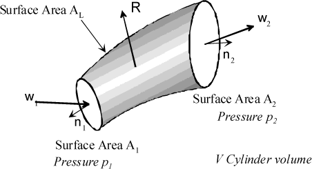
The fluid flow is proportional to governor position ε, Figure 3.7. That is:
[3.22] 
Figure 3.7. Effect of Governor on Flow

By applying the fundamental principle of dynamics, the characteristic equation of the driven system is:
[3.23] 
Where I2 corresponds to inertia, and K2 to the angular stiffness of the shaft. Coefficient C2 stands for the proportionality coefficient of the torque due to a governor position variation.
The two equations thus are:
[3.24] 
The system is written in relation to the modal characteristics:
[3.25] 
where:
[3.26] 
Let us define the system stability criterion through both of these equations. Let us use the Laplace transform for this purpose:
[3.27] 
The following equations are then obtained:
[3.28] 
This system of equations has non-zero solutions, provided that:
[3.29] 
That is, if:
[3.30] 
The stability criterion, according to the Routh criterion, is then written:
[3.31] 
Let us examine the case where there is no damping in the system (λ1=0). The criterion then becomes:
[3.32] 
The criterion cannot be verified. It can thus be concluded that, with no damping, the system is always unstable.
Figure 3.8. Positioning of Governor Eigenfrequency and Damping Ratio for Stability Purposes

In the case where there is damping, the following is obtained by developing the stability equation:
[3.33] 
It can be observed that this stability condition can be verified only if eigenfrequency ωp1 of the governor is higher than eigenfrequency ωp2 of the governed system. Under this condition, this equation is used to define the damping ratio to be obtained in the structure for stability purposes:
[3.34] 
This relation shows that it is hard to provide sufficient damping to make the system stable if the two eigenfrequencies are close to each other.
Let us analyze the behavior according to the two types of setting from equations [3.25]. Eigenfrequency ωp2 of the governed system is set to:
[3.35] 
It is possible to define the governor transfer function whose modulus and argument can be evaluated, Figure 3.9 and Figure 3.10:
[3.36] 
Figure 3.9. Governor Response (Gain)

Figure 3.10. Governor Response (Phase)

The governor eigenfrequency is assumed to be lower than that of the governed system.
That is:
[3.37] 
Figure 3.11. “Inertia”-Working Governor

Under these conditions, the governor behaves as follows:
[3.38] 
The following is then obtained around the eigenfrequency of the governed system:
[3.39] 
It can be observed that the phase shift between the governor motion and the governed system speed variation is equal to π, and the amplitude ratio is low, as illustrated in Figure 3.11. We then have:
[3.40] 
It can be observed that the effect of governing induces an unstable behavior; the “damping” term is negative. In this case, it is essential to provide damping to the governed system in order to ensure stability.
The governor eigenfrequency is assumed to be higher than that of the governed system. That is:
[3.41] 
Figure 3.12. “Stiffness”-Working Governor

Under these conditions, the governor behaves as follows:
[3.42] 
The following is then obtained around the eigenfrequency of the governed system:
[3.43] 
It can be observed that the phase shift between the governor motion and the governed system speed variation is zero, and the amplitude ratio is high and corresponds to the static gain, as illustrated in Figure 3.12. We then have:
[3.44] 
The system is stable. Governing induces damping.
Turbomachines are very present in aviation, through airplanes, helicopters or tiltrotor aircraft.
Figure 3.13. Different Propulsion Modes

The propeller consists of a hub which rigidly connects it to the engine shaft, and accommodates blades at its periphery. Each blade is a succession of airfoil elements whose thickness decreases from the center to the tip. A propeller is characterized by its number of blades, maximum diameter, pitch and setting angle. The latter is called pitch angle.
The setting angle corresponds to the angle between the mean aerodynamic chord and the rotation plane, Figure 3.14. On a multi-engine aircraft, in the event of failure of one engine, the propeller of the failed engine induces excessive drag. In this case, the blades are brought into the set of the relative wind, and their setting angle is then close to 90°: this position is known as feather, Figure 3.17.
Figure 3.14. Setting Angle or Pitch Angle Definition

The blade is subjected to various types of mechanical action. Only the effects of the aerodynamic forces and of inertia affect the blade setting angle.
In flight, the effects of inertia cause the equivalent of a twisting moment of the blade which tends to reduce its setting angle. This moment is termed “centrifugal twisting force” in some works.
Figure 3.15. Effects of Inertia on Blade Twisting

It can also be shown that the aerodynamic effects cause the blade to tend to a high pitch. This moment is termed “aerodynamic twisting force” in some works.
Figure 3.16. Effects of Aerodynamic Forces on Blade Twisting

When the setting cannot be modified in flight (fixed setting), the propellers are optimized for an aircraft speed close to the cruise speed. In this case, a limit rotational speed must not be exceeded as overspeed may results in damage to the engine or breakage of the propeller. This type of propeller is ideally suited to neither takeoff nor cruise speed. The engine speed of the airplane equipped with such a propeller increases and decreases with the airspeed, and the power control acts on the engine rotational speed.
Figure 3.17. Airplane (C-130) Variable-Pitch Propeller, With Feathered Blades

For variable-setting angle propellers, the pilot can adapt the engine and propeller to the current flight phase.
A governing system then enables the engine to be maintained at its optimum rotational speed. The engine speed of an airplane equipped with a variable-setting propeller remains constant even though the airspeed varies.
The pilot controls fuel flow variation through the throttle.
When the flow increases, the torque delivered to the rotor by the engine increases, which accelerates it. The engine speed is maintained constant by increasing or decreasing the blade setting angle.
The governing system, termed governing box, is located between the propeller and the engine, Figure 3.18, and uses the hydraulic power as control means.
Figure 3.18. Location of Governing Box

A device designed to change the blade setting angle in relation to the oil pressure is located at the aircraft nose, Figure 3.19. The piston equilibrium position, and hence the value of the blade setting angle, is obtained under the effects of oil from the governing box, spring and resistance to blade motion, Figure 3.20.
Figure 3.19. Blade Setting Angle Control Device

Conversion from piston translational motion to blade rotational motion is obtained by a rack and gear system, Figure 3.20.
Figure 3.20. Two-Blade Rotation Mechanism

The function of the governing box is to control the engine rotational speed and propeller setting angle. The engine rotational speed information is obtained by a flyweight system. The slide valve position is defined by its equilibrium under the action of the spring and centrifugal effects exerted on the flyweights. On the shaft, two notches are designed to route the oil to the propeller (so as to increase or decrease the setting angle) or to the hydraulic reservoir, under the centrifugal effects. In turboprop engine applications, the same oil is often used for engine lubrication and hydraulic regulation control.
Figure 3.21. Governing Box Normal-Speed Configuration

The system has been defined in such a way that the assembly is in equilibrium for the rated speed. Thus, a blade is in equilibrium under the aerodynamic and oil actions.
The rated speed can be adjusted by the pilot through a screw. The spring preload can thus be changed and hence the rated speed.
In the case of overspeed, the flyweights exert a greater force onto the slide valve. The arm then displaces by compressing the spring.
The hydraulic reservoir port is then blocked whereas the pitch control port is fully open. Oil is directed to the propeller and, through the gear system, changes the blade pitch, Figure 3.20.
Figure 3.22. Governing Box Overspeed Configuration

As the pitch angle increases, the aerodynamic forces will increase, thus causing the thrust and hence the resisting torque of the propeller. The dynamic system slows down, the blade control power supply port is blocked again, and the system then finds an equilibrium speed which corresponds to the governer setpoint.
In the case of underspeed, the speed decreases and the flyweights then exert a smaller force onto the slide valve. The pitch control port is then blocked whereas the hydraulic reservoir port fully opens. The spring, Figure 3.19, pushes the piston, which returns the oil to the hydraulic reservoir through the governor. The pitch angle increases, the aerodynamic forces will decrease, thus causing the propeller resisting torque to be reduced. The dynamic system accelerates, the reservoir oil return port is blocked again, the system then finds an equilibrium speed which corresponds to the governer setpoint.
As the pitch angle decreases, the aerodynamic forces will decrease, thus increasing the engine speed.
In the event of failure of the governing system, the blade changes to minimum setting on a single-engine aircraft, and to maximum setting on a twin-engine aircraft.
On an airplane, the pilot directly acts on the fuel flow. There is a regulation system at the gas generator and turbine, as on a helicopter. The main difference is the presence of an anticipator on the helicopter.
Figure 3.23. Governing Box Underspeed Configuration

As regards an aircraft such as the tiltrotor aircraft which has, depending on the flight phase, a behavior of the helicopter type (upon takeoff and landing) or airplane type (during cruise flight), the two types of regulation must be set up.
Figure 3.24. Tiltrotor System

On a helicopter, there is the same type of coupling between the power drive section (rotor, shafts, etc.) and the governed turbomachine.
The drive section applies a torque excitation to the structure which then starts vibrating. The governing system is then actuated through these speed variations.
The problem is obviously to prevent the system from having an unstable behavior.
The behavior will depend on the type of engine used and relevant performance data.
Figure 3.25. Coupling Between Helicopter Rotor and Turbomachine

A turbine converts the fuel combustion energy into mechanical energy. There are two types of turbine: coupled turbines and free turbines.
These different technologies exist according to the compromise between system performance and weight.
In coupled turbines, the compressor and turbine are secured to the same shaft. This solution provides a good effective efficiency, provided that the rotational speed is close to the rated speed.
This system is provided with no starting torque. It cannot drive receiving machines which require a starting torque, as well as machines which require a substantial torque at low rotational speeds.
Figure 3.26. Coupled Turbine

Figure 3.27. Schematization of Powerplant (PP), With Coupled Turbine

As coupled turbines badly withstand load fluctuations, the idea consists in separating the two functions of the turbine by dividing it into two sections: a compression turbine section, which drives the compressor, and a power turbine, termed free turbine. For a constant turbocompressor speed, the power and torque of the free turbine may largely vary. For the case of the stopped free turbine, its torque reaches the maximum value, which provides traction of the vehicles requiring a substantial starting torque. A twin-shaft turbine well withstands power fluctuations.
Figure 3.28. Comparison of Torque Curves for a Coupled Turbine and a Free Turbine

Figure 3.28 gives a comparison of the torque curves for a coupled turbine and a free turbine.
Figure 3.29. Free Turbine
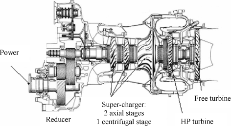
The powerplant comprises the gas generator and the free turbine which drives the receptor, Figure 3.30.
Figure 3.30. Schematization of PP (Powerplant)

The function of the governing system is to automatically adapt the engine to the propulsion requirements; the parameter used is the fuel flow, noted Q.
The helicopter requires that the rotational speed of its rotor be almost constant (about 1%) regardless of the conditions and load applied. To this end, it is necessary to detect the speed variations so as to meter the fuel. The present governing systems are of the digital type and use a computer to generate the governing law. In order to illustrate the behavior of governing systems, let us use the example of hydromechanical governing which is still used on some aircraft. The data used were taken from the Instruction Manual of Turbomeca1.
The rotor of a helicopter is subject to much more stresses than that of an airplane. Helicopter flight mechanics requires frequent actions on the blade incidence. A pitch change significantly increases the rotor resisting torque; the turbine cannot react instantaneously because of the high rotor inertia. It is then necessary to use a free turbine, Figure 3.30.
Figure 3.31. General Governing System Operation
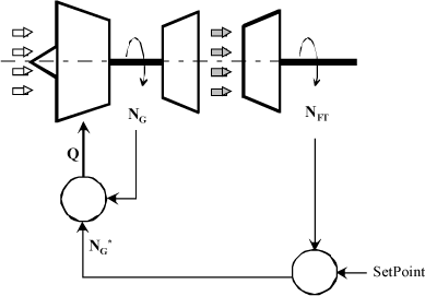
Figure 3.32. Essential Parameters of Control Loop
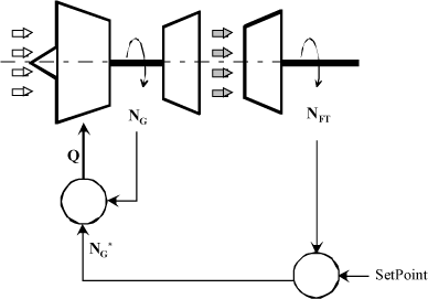
The following must be distinguished in Figure 3.32:
– gas generator rotational speed, noted NG;
– free turbine rotational speed (and rotor speed, proportionally), noted NFT;
– fuel flow injected into the combustion chamber, noted Q.
The free turbine rotational speed NFT may vary due to several reasons:
– pilot action on the collective pitch control;
– helicopter external conditions (climatic, wind force or direction change for instance);
– aircraft weight variation (use of fuel for instance).
Figure 3.33. Different Governing Components

We propose to expose the method usually applied for governing a helicopter free turbine.
Rotational speed NFL variations are information which is acquired by the free turbine governor. This is a proportional governor which determines an NG* signal (setpoint) as a function of the variation of NFT and pitch that the pilot requests.
Figure 3.34. Free Turbine Governor Schematic
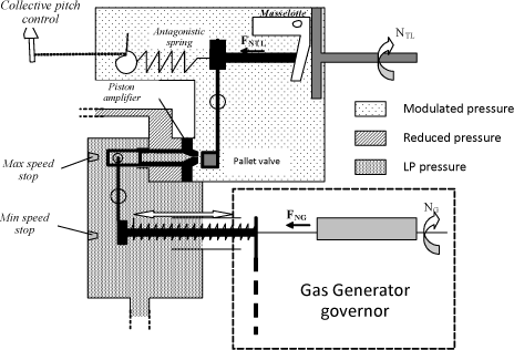
The speed NFT information is given by the equilibrium position of the control rod, under the action of the effects of inertia of a system consisting of flyweights (centrifugal effects) and a spring.
The other end of the hinged lever accommodates a potentiometric jet, with a lever moving before its calibrated port. The leakage through this jet determines the modulated chamber pressure. The amplifier piston (subjected to a reference pressure, in other words reduced pressure on the one hand, and to the modulated pressure on the other hand) determines the NG setpoint transmitted to the gas generator governor through a setpoint plunger and lever. The governing system operates according to whether the speed increases or decreases.
a) Case of Underspeed or Collective Pitch Increase
If the collective pitch is increased, the antagonistic spring is compressed. In the same way, if the speed decreases, the flyweight will have another equilibrium position. In both cases, the lever will move and find another equilibrium position which will tend to reduce the modulated gas flow.
As a matter of fact, the modulated gas pressure increases and changes the equilibrium position of the amplifier piston. The amplifier piston motion then drives the setpoint plunger through another lever. The setpoint plunger moves to increase the fuel flow: this motion represents the NG* setpoint.
It is necessary to insert a maximum speed stop to prevent the plunger from giving an excessive setpoint. The latter limits the NG* setpoint so as to prevent the fuel demand from damaging the engine.
Figure 3.35. Governor Schematic Case of Underspeed or Collective Pitch Increase
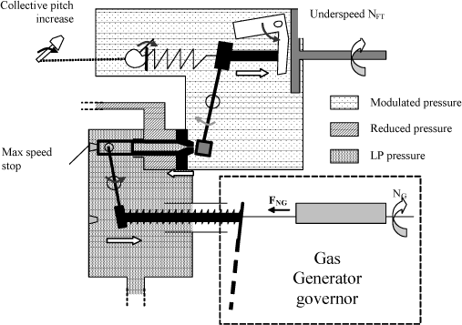
b) Case of Overspeed or Collective Pitch Decrease
If the collective pitch is decreased or the speed increases, the previously described effects are reversed, thus reducing the fuel flow through the amplifier piston and setpoint plunger.
A minimum speed stop prevents the plunger from giving an excessively low setpoint, thus preventing the engine from stalling (lack of fuel).
Figure 3.36. Governor Schematic Case of Overspeed or Collective Pitch Decrease

For proportional governing, any load variation leads to variation of the governed value which moves away from the setpoint (offset behavior phenomenon).
In the case of the helicopter, a collective pitch (θ0) increase causes the aerodynamic load to increase, thus reducing the rotational speed (NFT).
This speed change reduces the lift, which may be unacceptable for the aircraft performance, and increases the twisting stresses in the control linkage. As a matter of fact, if the rotational speed drops, the torque must be increased to maintain the power.
The governing system detects this speed change, and modifies the fuel flow accordingly, so as to cause the engine power to vary and thus restore the engine speed.
Such anticipation can be done either mechanically, as illustrated in Figure 3.38, or electrically, Figure 3.39. In practice, the response time due to detection is not negligible as it affects the engine system reactivity.
The function of the anticipator is to anticipate such vibrations. Connected to the collective pitch control, the latter will anticipate the flow variation, thus allowing for reduction of the response time and offset.
Figure 3.37. Offset Behavior Phenomenon With and Without Anticipator

Without anticipator, the engine speed-versus-collective pitch law is linear: a pitch increase results in an engine speed reduction. For example, on Puma SA330, the speed would change from 272 rpm low-pitch to 256 rpm high-pitch.
The 265 rpm speed would correspond to the mean power. On this aircraft, the anticipator acts on the engine speed setpoint (NFT) while canceling the offset and also overcompensating it. The engine speed increases with the pitch, Figure 3.40.
Figure 3.38. Mechanical-Type Anticipator Schematic

Figure 3.39. Electrical-Type Anticipator Schematic

Figure 3.40. Effect of Anticipator on Engine Speed-Versus-Pitch Law

Let us study a simple case. The drive shaft, turbine  and rotor
  are modeled by one deformable shaft, the inertia effects of which are neglected, and by two undeformable disks, Figure 3.41.
The two disks have an inertia noted It for the turbine, and Ir for the rotor. The shaft is modeled by a torsion spring with stiffness ka. Damping is introduced by viscous damping coefficient ca.
Application of the fundamental principle to turbine  and then rotor
  gives the following two equations of motion:
[3.45] 
Cm and Cr correspond to the torques exerted onto the turbine or rotor.
Figure 3.41. Turbine/Rotor Drive System Modeling

Using the Laplace transform, the system of equations becomes:
[3.46] 
The system can thus have the following matrix form:
[3.47] 
Analyzing the homogeneous system without damping allows for evaluation of the system eigenfrequencies using the following characteristic equation:
[3.48] 
That is, by developing:
[3.49] 
The eigenfrequencies thus are:
[3.50] 
The zero eigenfrequency corresponds to a rigid mode (whole motion with no shaft deformation). The second eigenfrequency corresponds to a mode whose interaction with the governing system must be checked.
The governing system studied uses a rotational speed sensor coupled to an actuator which modifies the flow accordingly, Figure 3.44. The sensor is based on a Watt’s governing system. In the example proposed, it can be observed that, in practice, free turbine governing (NFT) and gas generator governing (NG) are superimposed, Figure 3.43.
Figure 3.42. Location of Coupled Turbine in Helicopter
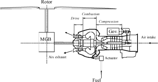
Figure 3.43. Engine Control Action Schematic

Figure 3.44. Governing System
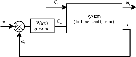
An instability phenomenon may appear when the phase shift or amplitude between the measurement of the deviation to be corrected and the effective governing action are such that the rotational speed varies around the rated speed in self-induced way.
The amplitude of such oscillations then increases up to damage to the aircraft, or turbine shutdown by the pilot.
To be analyzed, this phenomenon requires the introduction of the behavior of each component of the governing system. The purpose is to define a sizing criterion which ensures stability.
The system studied includes a coupled turbine with a single Watt’s governor which was the system used on helicopters in the 1960s.
The sensor is modeled by a flyweight governor, based on the descriptions in the preceding paragraphs. The control rod will have a displacement, noted x, as a function of the rotational speed variation.
The actuator has a proportional behavior within the frequency range studied. Thus, fuel flow Q is proportional to displacement x of the control rod:
[3.51] 
where A is the negative proportionality coefficient.
The sign of A shows that, when the speed increases and hence x increases, the flow decreases.
The turbine has also a proportional behavior. Thus, the induced torque Cm is defined as a function of the flow by the following linear law:
[3.52] 
The governing system usually has a second-order behavior, with mreg the governor inertia, kreg its stiffness, and creg introducing a phase delay. The behavior equation is therefore:
[3.53] 
where ω0 is the system rated speed.
The drive shaft is modeled by a system consisting of a mass, a spring and a torsion damper of stiffness ka and damping coefficient ca, such as it has been defined in the preceding paragraph.
The whole system can be modeled such as illustrated in Figure 3.45.
Figure 3.45. Complete Control Linkage System Modeling

The two equations of motion of the turbine and rotor [3.47], given from the speeds, are:
[3.54] 
The governing system equation gives:
[3.55] 
The following system of equations is thus obtained:
[3.56] 
Where:
[3.57] 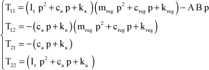
The determinant is given by:
[3.58] 
It can be observed that the system results from superimposition of two stresses:
[3.59] 
The transfer function between resisting torque Cr and speed ωt is defined by:
[3.60] 
In order to check for system stability, the Routh criterion can be used for this transfer function H.
Let us consider the case where damping ca is zero.
The denominator can be simplified to p and expressed in the following form:
[3.61] 
By introducing the modal characteristics:
[3.62] 
Table 3.1.
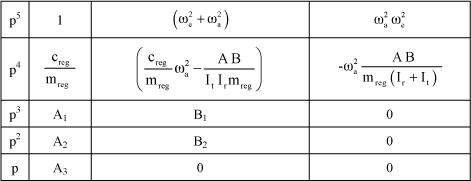
The Routh criterion conditions then are:
[3.63] 
[3.64] 
[3.65] 
First assuming that ωreg<ωa, the condition of equation [3.63] leads to:
[3.66] 
and the condition of equation [3.65] leads to:
[3.67] 
It can be shown that both of these inequalities are contradictory. The system cannot be stable if ωreg<ωa.
Then assuming that ωreg>ωa, as condition [3.65] is the most limiting one, the system must check the following condition:
[3.68] 
The correction is more able to match the shaft vibrations and damping is less required as the governor frequency increases.
Whenever inertia Ir is infinite, the governor damping condition is reduced to:
[3.69] 
Figure 3.46. Stability Area as a Function of Governor Eigenfrequency and Governor Damping
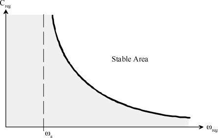
The second configuration (where the governor eigenfrequency is lower than the shaft one) is not possible if shaft damping is considered as being zero since the system stability is ensured by this damping only. In this configuration, the governor action favors vibrations. The system is stable only if the shaft eigendamping is high enough to prevent degeneration of the oscillations. But the equation complexity does not allow a simple criterion to be highlighted in this configuration. Stability will therefore be established through attempts by calculating the coefficients of the Routh table or by simulation.
The problem described in this chapter is related to the instability caused by nonmatching of the engine governing with the helicopter control linkage. The governing used is of the hydromechanical type.
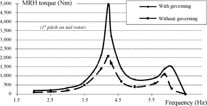
In order to characterize this instability, the dynamic identification of the control linkage has been obtained by an excitation through the collective variation of the tail rotor blades. To this end, a sine swept within the 2–6.5 Hz range has been used.
Figure 3.47. Control Linkage Identification Schematic
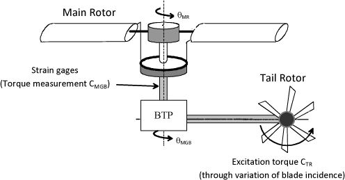
Low-power identification, Figure 3.48, shows that the torque is greater with governing. Damping is reduced by governing, more particularly on the first mode of the torsional system at 4.2 Hz. The deformation of this mode shows substantial deformations at the connection between the rotor and the MGB. Governing is not adapted to the torsional system. For a higher power, a divergent oscillation was observed which required the pilot to shut down the engines using the throttles.
For this type of problem, there are several solutions depending on the type of governor used.
For digital-type governors, there are two methods: notch filter and active control systems. In the case of notch filters, this consists in filtering the problematic frequency (4.2 Hz in this case) in order to make this mode transparent as regards governing. At this frequency, the governing system no longer injects fuel, the torsional system regains its natural damping. By observing the NFT speed, active systems will inject a quantity of fuel so as to counter the natural oscillations of the rotor. This type of corrector often has a derived action so as to have some phase advance for the torque effects generated by the turbine to be opposed to the rotor oscillations.
Figure 3.48. Dynamic Identification of Torsional System of a Helicopter Through Swept-Sine Excitation of Tail Rotor
As regards hydrodynamic governors, a solution consists in modifying the transfer function of the governor at the mode frequency, Figure 3.49. The purpose is not to modify the transfer function below 1.5 Hz in order to guarantee a good quality of control, and at least 3 dB attenuation to be obtained at 4.2 Hz.
Figure 3.49. Governor Transfer Function Modified. Fuel Flow/Gas Generator Speed

This modification can be obtained by playing on the shape of the metering needle. The constant ΔP valve is in the form of a small device parallel-connected to the metering device, downstream of the fuel pump. The fuel from the pump is at pressure P1 applied to the left side of the tight seal. The fuel directed to the carburetor is at pressure P2 applied to the right side of the tight seal. ΔP= P1-P2=constant is searched for.
When P1 increases (or P2 decreases), the seal will move to the right, thus more opening the fuel cross-section area, P2 will then increase until the deviation returns to the initial value.
When P2 increases (or P1 decreases), the seal will move to the left, thus obstructing the fuel cross-section area to the pump, P2 will then decrease until the deviation returns to the initial value. The “excess” fuel returns to the pump at pressure P0.
The spring is used to determine the desired ΔP value. As a matter of fact, upon equilibrium, the force exerted by P1 is equal to the sum of the forces exerted by P2 and spring. The force exerted by the spring depends on the stiffness and related elongation. Both of these parameters are set by the user (the elongation in particular can be varied with the thumbwheel on the right of the spring).
Figure 3.50. Metering Device

FP1=FP2+Fspring hence FP1−FP2=Fspring=constant. Therefore, constant P1−P2 depends on the spring stiffness. The position of the metering needle is determined by the gas generator governor according to the power required by the rotor.
The governor has been voluntarily damped.
To this end, the needle of the constant ΔP valve has been elongated so as to increase the response time.
Figure 3.51. Arrow Tip Modification
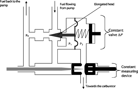
It has been sharpened so as to increase the response time and thus reduce the gain. As a matter of fact, the system oscillates when entering resonance.
The valve will oscillate at the same time since the metering device will also be actuated. The P2 pressure will also vary, and the valve will have to take up the deviation.
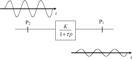
By roughly considering the constant ΔP valve as a first-order system, if the response time is increased, P1 will not have enough time to reach what is requested by P2 before the latter starts varying.
Therefore, the P1 curve is more flattened that the P2 curve (See Figure 3.52).
Nevertheless, the difference P1−P2 is assigned with a new value but remains constant (which is the most important thing).
Figure 3.52. Effect of Response Time on Valve Response
More simply, sharpening the tip prevents the engine from racing since the needle will not excessively oscillate.
Figure 3.53. Effect of Damped Governing

It can be observed that the with/without governing difference is much less obvious as previously. The max torque is then about 2600 N.m whereas previously 5000 N.m were easily reached, which was very detrimental to the mast.
This modification allows for satisfactory operation of the helicopter within its flight envelope.
1 Turbomeca was created in 1938 by a Pole engineer, Joseph Szydlowski (born on November 21, 1896 in Chelm in Poland). Today, Turbomeca are the greatest worldwide manufacturer of low- and medium-power turbines, and are part of the Safran Group.