Figure 4.1. Internal Damping for Connection With Bearings

Present technical breakthroughs focus on increased rotational speed of machines. The essential problem of machines rotating at substantial speeds is the control of reactions in the bearings through appropriate balancing [KRY 03]. There is another source of vibrations which gives rise to dynamic instability and is termed self-sustaining instability (self-excited vibrations).
The first examples of such type of instability were observed at the beginning of the last century, in turbocompressors for blast furnaces, and chemical industry [EHR 99, VAN 88]. Such instabilities result in shaft bending vibrations at nonsynchronous frequencies (not corresponding to the shaft rotational speed) for operating speeds higher than the 1st critical bending frequency.
When there is no vibration monitoring, instability may cause damage to the machine. Often, the vibration amplitude is limited by a nonlinear effect, and a limit cycle is reached. Physically, the limit cycle is due to the fact that the increased vibration amplitude results in rotating parts contacting non-rotating components, which led to limit the amplitude through damping. Under such conditions, damage to components or even destruction is frequently observed.
Self-sustaining instability of the rotor induced delayed development of turbomachines for the industry and specially aviation. For a long time, theoretical nonunderstanding of the phenomenon led the manufacturers to only perform experimental analysis. It was observed that two types of damping had to be distinguished for rotating systems: internal damping and external damping.
Internal damping is related to the dissipation due to a relative motion between rotating parts.
Such type of damping is encountered for several connections, such as splines, clampings, sealing components placed in the rotating reference system, etc. (See Figure 4.1).
Figure 4.1. Internal Damping for Connection With Bearings

External damping is caused by energy dissipation due to a relative displacement of a system component rotating with the stationary reference system (the frame, often), Figure 4.2.
Figure 4.2. External Damping for Connection With Bearings
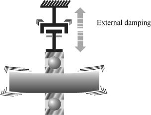
The presence of internal damping and the instability phenomenon were correlated by experimentation. In the same way, it was observed that external damping reduces the risk of instability.
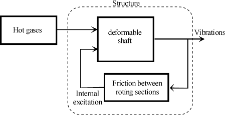
As regards self-induced vibrations related to internal damping, the energy which sustains vibrations is provided by an external source, Figure 4.3.
Figure 4.3. Schematization of Self-Sustaining Instability

This will be the case of the engine which drives a compressor, or hot gases which provide energy to the power turbine stage of a turbojet engine.
This energy source causes divergent vibrations through a system inherent mechanism. Self-induced vibrations differ from forced vibrations: the force which causes instability is caused by the motion itself and not by an external force.
It can be observed that, if the exciting source disappears, vibrations carry on, contrary to what happens for a forced excitation.
Figure 4.4. Case of Internal Damping for a Turbine
The difference between forced vibration and unstable self-induced vibration can be illustrated by the example of a hard-bearing balancing machine, Figure 4.5 [KRY 03].
Figure 4.5. Hard-Bearing Balancing Machine

Figure 4.6. Balancing Machine Bearing Setup

Key to Figure 4.6:
– m: rotating mass,
– M: suspended mass,
– k: suspension stiffness,
– e: eccentricity,
– Ω: rotational speed.
Let ωp be the eigenfrequency and λ the reduced damping defined by:
[4.1] 
By using the setup proposed in Figure 4.6, it can be demonstrated that the amplitude of the relative displacement is given by [KRY 03]:
[4.2] 
where:
[4.3] 
Figure 4.7. Amplitude of Relative Motion Versus Rotational Speed

For very low rotational speeds (ωr<<1), the relative displacement is very low. The shaft is hardly deformed. Conversely, the reactions at bearings exist and can be measured in order to perform the balancing operation. It can thus be shown that, for the case of forced vibrations, the excitation force exists (unbalance) independently of the shaft motion. In this case, the shaft does not vibrate despite the presence of the excitation force.
The purpose of this section is to propose a simple physical explanation for better understanding of this phenomenon and giving a sizing criterion.
The phenomenon described in this chapter is characterized by vibratory oscillations not synchronous with the shaft rotational speed. Under this condition, rotary bending of the shaft is observed. Using a strain gage installed on the shaft, bending deformation is observed at a frequency differing from the rotation frequency and precession frequency.
This phenomenon mainly arose with the arrival of light constructions which, for optimization criteria, are sized to operate above their first critical frequency (supercritical speed). Appearance of this instability is independent of the balancing condition of the rotating system.
Damping internal to a rotating structure is due to:
– friction between several parts making up the rotating section. The mechanism may present a relative displacement or play which, when associated with friction, results in instability under some conditions, Figure 4.8. This may be encountered in incorrect clampings, spline- or key-type couplings with play, etc., or
– damping of the materials constituting the rotor. Such effects are often considered as negligible compared to the effects of the first type if any.
The first type of damping should be modeled by dry friction. Such modeling has the drawback of complexifying the model and calculations. For an easier analytical approach, in this study, internal friction is modeled by Newtonian viscous damping. This model offers sufficient approximation of the behavior to understand the mechanism and derive rules.
The second type of damping is modeled by viscous damping.
Contrary to other forms of instability, this one is not intuitive. We intend to give a first simple illustration of this phenomenon, by using the De Laval rotor model. Then, we will define a sizing criterion using a flexible shaft model.
Figure 4.8. Rotating System With Relative Displacement

The De Laval rotor model, Figure 4.9, also known as “Jeffcott’s Rotor”, is sufficient to illustrate the origin of the instability due to internal damping [EHR 99, VAN 88].
The rotating system consists of a flexible shaft whose inertia effects are negligible, and a rotor disk considered as undeformable. In this section, center of inertia G does not necessarily correspond to rotation coincidence point A.
It was shown that, under the single effect of unbalance, the trajectory of center of inertia G was a circle traveled at the same frequency as the rotor rotation frequency, Figure 4.10 [KRY 03]. We have a synchronous gyrational motion.
Figure 4.9. Rotating System Modeling – De Laval Rotor

Figure 4.10. Synchronous Precession Motion
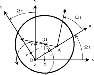
Let us consider the De Laval rotor of Figure 4.9. If a deflection is imposed to the shaft, this results in conventional distribution of stresses with a compression area and an extension area, Figure 4.11.
Figure 4.11. Stress Distribution for a Bending Shaft

It can be observed that, if the “shaft rotates” about the theoretical rest axis at speed Ω, the distribution will remain the same regardless of the angular position, Figure 4.12. The normal stress on a facet of normal z is then constant [KRY 03].
Figure 4.12. Stress Distribution During Precession Motion

In some cases, an asynchronous motion can be observed from center of rotation A. This motion may initiate by an external action, even temporary, which tends to accelerate or slow down the rotational motion of point A. The two rotational speeds are then different, Figure 4.13.
Figure 4.13. Asynchronous Precession Motion

Let us show that this speed difference induces a force which, depending on its sign, can increase (unstable system) or decrease (stable system) this speed difference. It is necessary to introduce the coordinates of a point in the rotating reference system in order to define the model of this mechanical action.
Let (x, y) be the coordinates of center of inertia G in stationary reference system R0. Then set:
[4.4] 
Let (u, v) be the coordinates of this point in rotating reference system RΩ, and then set:
[4.5] 
With the rotor rotating at constant speed Ω, the following relations are shown by projection:
[4.6] 
From relation [4.6] and using complex notations [4.4] and [4.5], it can be shown that:
[4.7] 
This reference system change is necessary since it is observed that internal damping is modeled in rotating reference system RΩ whereas it is necessary to analyze its effect in stationary reference system R0.
Structural damping mentioned herein is dry friction between several rotating components. This may specially be due to the connection between the disk hub and the shaft.
Generally, dry friction does not depend on the size of the slipping surfaces, but is directly proportional to the force normal to the plane of the contact surface.
In practice, it can be observed that not only the dry friction force is opposed to the relative speed but also is a function of the relative speed of the two slipping components, noted V, Figure 4.14.
Figure 4.14. Dry Friction Behavior

Let us consider the spline connection, Figure 4.15. When the shaft is deformed, slipping appears at the splines. The slipping speed is then associated with shaft deflection ξ at the splines.
Figure 4.15. Effect of Deflection on Relative Motion

Experience of this type of phenomenon thus leads us to model the effect of internal damping by an action of the following type:
[4.8] 
In the case of small motions, which is sufficient to determine whether the motion is stable or unstable, the effect of internal damping is modeled by an action of the Newtonian viscous fluid type of the following form:
[4.9] 
Let us attempt to express this force as a function of z, hence from [4.9] and [4.7]:
[4.10] 
Which gives, by reverting to Cartesian coordinates (x,y):
[4.11] 
The following can be observed:
– terms  and
and  correspond to damping which can be modeled by dashpots working along x and y;
– terms ci Ω x and –ci Ω y are a function of the displacement, hence comparable to stiffness; they also depend on the rotational speed. They are known as cross-coupled stiffness. Most often in works, these terms are modeled by 45° stiffness values [EHR 99, VAN 88], Figure 4.16.
Figure 4.16. Cross-Coupled Stiffness Modeling

This representation is not physical at all and may be open to misinterpretation.
Cross-coupled stiffness acts perpendicularly to the shaft displacements (a displacement along the x-axis induces a force along the y-axis, and this is why cross-coupled stiffness is represented at 45°).
Moreover, even though this representation uses known mechanical parameters {K, C}, the latter do not necessarily correspond to actual components. It can indeed be observed that one of the stiffness values is negative.
It was demonstrated that, for a flexible shaft not balanced, the trajectory of the center of inertia is a circle of radius e [KRY 03].
Let us attempt to illustrate that, if for any reason the system moves away from its equilibrium position, the previously described internal force may make the system unstable.
Figure 4.17. De Laval Rotor Setup

The coordinates of the mass center in the stationary reference system versus the trajectory radius are given by:
[4.12] 
Thus, the following can be written from the definition of forces [4.11]:
[4.13] 
Or else:
[4.14] 
By expressing the forces in rotating reference system  :
:
[4.15] 
Figure 4.18. Internal Forces

Then:
[4.16] 
The radial force which causes centering is therefore zero. The tangential force can be either stabilizing (opposed to the motion) or destabilizing (motive) depending on its sign.
Physically, the rotor is subjected to two forces:
– a force from the dashpots. It is opposed to the rotational motion of the mass and limits the amplitude increase. This part is represented by part –ci e ωwhirl;
– an excitation force due to cross-coupled stiffness. It is directed in the same direction as mass rotation, and increases the amplitude, term ci e Ω. If this force becomes greater than the force from damping, the amplitude constantly increases and the system becomes unstable.
This illustration shows that, depending on the sign of (ωwhirl–Ω), internal damping may cause a destabilizing force to appear.
It can be observed that, for a gyrational motion not synchronous with the shaft eigenrotation, there is cyclic variation of the normal stresses associated with the facet of normal z as a function of its position, Figure 4.19.
Figure 4.19. Stress Variation for an Eigenrotation

Owing to the shaft precession at speed ωwhirl, the cyclic variation frequency for point A is defined such that:
[4.17] 
The materials usually used for shafts (metallic) most often comply with a linearelastic behavior law (Hook’s law). However, for this special case, material damping must also be taken into account. The shaft is considered as a viscoelastic material.
Simple modeling of the relation between deformation and stress in a viscoelastic material is given by the Kelvin-Voigt model.
Figure 4.20. Kelvin-Voigt Material Behavior Model
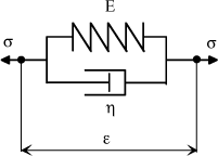
Let us illustrate the behavior of a bending shaft on its first bending mode using the Kelvin-Voigt model.
The following behavior relations are deduced from this model:
[4.18] 
where:
– E: Young’s modulus,
– η: damping coefficient.
Figure 4.21. Behavior Modeling for First Bending Mode

The behavior law which models the shaft deformation behavior therefore is:
[4.19] 
For a harmonic behavior, the following can be shown:
[4.20] 
where:

Which gives the following transfer function:
[4.21] 
The phase shift induced by the material behavior is such that:
[4.22] 
It can be observed that, when the frequency is low, the phase shift due to the material viscous behavior is negligible.
If the frequency is high, the phase shift between stresses and deformations increases and is no longer negligible.
As the phase shift is negative, the stresses are in phase advance in relation to the deformations.
This means that, when the shaft is deformed, the associated stress occurs ahead of time.
The preceding study showed that, depending on the frequency of the deformation cyclic variations, the stress response was not the same.
Let us note ω the frequency corresponding to the cyclic variation of deformation at a point of the shaft with:
[4.23] 
Two cases can then be observed. Either ω is small and this corresponds to Ω close to ωwhirl, or ω is great (which corresponds to Ω greater than ωwhirl).
Figure 4.22. Stability According to Ω and ωwhirl

In this case, Ω<ωwhirl. Stresses and deformations are in phase. The zero-deformation and stress axes are merged (the deformation axis is imposed by the shaft deflection). The shaft stresses create an elastic force perpendicular to the zero-stress axis.
Figure 4.23 Stabilizing Restoring Force

In this case, the elastic restoring force is directed to the center and tends to make the shaft return to its original position. It takes no part in destabilization.
In this case, Ω>>ωwhirl is frequent. The phase shift then increases and may be great. The phase shift will physically result in an angular shift between the zero-deformation and stress axes. As the zero-deformation axis is imposed by the shaft deflection, the axis which rotates about the neutral axis is the zero-stress axis.
Figure 4.24. Destabilizing Effect of Shaft Internal Damping

Subsequent to rotation of the zero-stress axis, the elastic restoring force changes direction and a destabilizing component tangential to the motion appears.
The shaft internal damping can then take part in shaft stabilization or destabilization.
The cyclic changes to the shaft stresses create a phase shift between the deformations and stresses; this phase shift causes creation of a destabilizing force which tends to increase the shaft rotational speed, thus favoring instability.
Other phenomena, such as gravity or a stationary lateral force, may also cause cyclic changes to the stresses and deformations, and favor instability.
The axial slip for the first mode can be defined by the setup proposed in Figure 4.25.
Figure 4.25. Deformation Setup for First Bending Mode

The length for the first deformation mode is given by:
[4.24] 
By limiting to the first order, it can then be shown that:
[4.25] 
For the first bending mode, the deformation can be expressed by:
[4.26] 
It can then be shown that:
[4.27] 
That is axial variation Δ:
[4.28] 
The axial shortening is obtained as a function of the radial deflection. It may induce friction in the connections and thus internal friction.
This illustration highlighted causes and effects on the instability phenomena due to internal damping. Nevertheless, sizing criteria cannot be derived from it. Let us try to do so in the following paragraphs.
To illustrate the stability criterion determination approach, let us use a flexible shaft associated with a rigid rotor disk, noted S [LAN 97].
Figure 4.26. Flexible Shaft Model for Instability Phenomena
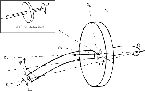
Let us assume the following:
– the rotor disk swivel angles, θ and ψ, are considered as small;
– this assumption is sufficient to determine whether the motion is unstable or not;
– rotational speed Ω is constant;
– the effects of gravity are negligible in relation to the effects of other mechanical actions.
Let  be the stationary reference system, and
  the rotating reference system related to the shaft. The rotations are defined in Figure 4.27.
Let us set up the equations of motion from the Lagrange equations.
As the angles are small, it can be assumed that point A moves in a plane perpendicular to axis z0. Its coordinates are noted (u,v,l) in the stationary reference system:
[4.29] 
Figure 4.27. Reference Systems Associated With Rotor Disk

The system kinetic energy is due to the disk and shaft. The kinetic energy of disk S takes the following form:
[4.30] 
As the rotor has revolution properties, its inertia matrix is given by:
[4.31] 
Now, we have the following:
[4.32] 
Then we show that:
[4.33] 
For small motions, developing to the second order gives:
[4.34] 
The shaft kinetic energy has an influence on the stability problem. To this end, the following setup is used.
Figure 4.28. Flexible Shaft Setup for Instability Phenomena
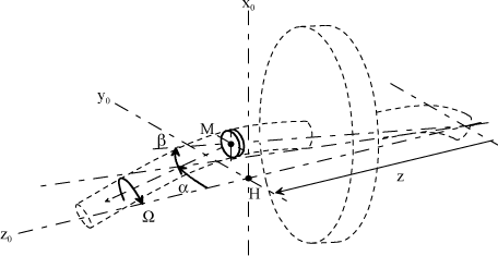
The position of point M is noted by:
[4.35] 
The solid section of very small thickness dl is such that the inertia matrix is compared to the following form:
[4.36] 
Thus, the shaft kinetic energy is expressed as follows:
[4.37] 
Parameters x, y, α and β are a function of position z. Their values will depend on the way the shaft will be deformed. In practice, this depends on the vibration frequency considered.
Let us study the first bending mode whose deformation h(z) is known for a shaft on two mounts of length L.
Let us set:
[4.38] 
Angles α and β are considered as small, and approximated by:
[4.39] 
It can be observed that the rotor disk parameters, at abscissa 1 along the axis, become:
[4.40] 
[4.41] 
Then, by making the variable change, the following kinetic energy expression is obtained:
[4.42] 
and:
[4.43] 
It can then be observed that:
[4.44] 
Where:
[4.45] 
The potential function due to elastic deformation of the shaft is given by:
[4.46] 
where:
– E: Young’s modulus,
– I: shaft inertia.
Using the variable change [4.38] and [4.39], it can be shown that:
[4.47] 
where:

Internal damping is modeled by two dashpots placed at position Li.
Figure 4.29. Cross-Coupled Stiffness Modeling
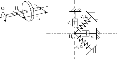
We have:
[4.48] 
External damping is modeled by two dashpots placed at le along directions x and y. The dissipation function is then:
[4.49] 
where C’e is the external damping coefficient.
Then:
[4.50] 
Figure 4.30. External Damping Modeling

The Lagrange equations are:
[4.51] 
Then:
[4.52] 
Let us analyze the system stability by observing the type of solution of the system of equations [4.52].
Let us set:
[4.53] 
Then, by adding up the two system equations [4.52], we have:
[4.54] 
where:

The solution is assumed to be of the following form:
[4.55] 
From the roots of characteristic equation [4.54], we obtain stability conditions. Simply study the sign of their real part.
The roots of characteristic equation [4.54] are:
[4.56] 
Remind that:
[4.57] 
[4.58] 
where:

The stability condition is such that the real parts of all roots are zero or negative.
It can then be observed that the following is necessary:
[4.59] 
That is, by simplifying:
[4.60] 
This condition can then be expressed from rotational speed Ω:
[4.61] 
That is:
[4.62] 
where:

It can be observed that the motion pseudoperiod is given by the imaginary parts of roots [4.56]. Thus we have:
[4.63] 
where:

Let us analyze the result for a drive shaft featuring no rotor, Figure 4.31.
Figure 4.31. Deflection of a Single Shaft on its First Bending Mode
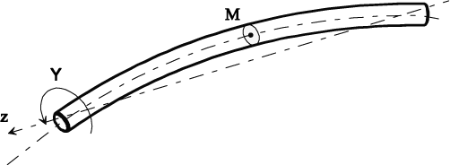
From the preceding results, it can be shown that the stability criterion is written:
[4.64] 
The following can be observed:
– instability occurs in the supercritical envelope for the first shaft bending mode, Ωins>Ωc;
– external damping plays a stabilizing role (stability limit speed increased);
– internal damping reduces the stability limit speed.
There are several methods to improve stability:
– increase the system eigenfrequency,
– reduce internal damping,
– increase external damping.
The first method requires modification of the system (replacement of bearings, reduction of turbine mass, etc.) and causes modification of the critical frequencies at the risk of resonance in operating area. The second method is limited; it is possible to reduce internal damping by reducing the clearances between all parts making up the turbine, but it cannot be completely eliminated. The last method is the simplest one and is commonly used in aviation to improve stability of engines.
Let us analyze a single shaft with the following geometric data:
– length L: 400 mm,
– inside diameter D: 58.5 mm,
– thickness e: 1.7 mm
Figure 4.32. Hollow Shaft Modeled by a Beam on Two Mounts

The material used is steel with the following characteristics:
– Young’s modulus: 210 MPa,
– density: 7800 kg/m3.
The system studied changes between 0 and 10,000 rad/s during operation.
Dampings were evaluated from tests intended to measure the instability frequencies for several spline lengths.
The dampings for this application were identified such as:
– internal damping Ci: 1100 N/ms-1,
– external damping Ce: 440 N/ms-1.
Internal damping is due to friction of the splines on the shaft, Figure 4.32.
Stability condition [4.64] gives a stability limit frequency equal to 50 Hz.
Figure 4.33. Response Time Spectrum in Starting Phase, Acceleration Measured on Casing

In order to prevent the effect of internal damping due to the splines, the solution found consists in introducing a deformable component, Figure 4.34.
Figure 4.34. Technical Solution to Prevent Self-Sustaining Instability

Shaft shortening caused by bending deformation is taken up by a deformable component. This type of solution dissipates very little energy compared to the other solution.
The internal combustion turbine, the compressor and turbine rotors of which are secured to the same shaft, is termed single-shaft turbine. Correct efficiency is provided only when the rotational speed of the assembly is close to a defined rated speed.
Reduction of the rotational speed reduces the air flow and compression ratio. The effective efficiency as well as the torque and power are decreased. Thus, a singleshaft turbine has no starting torque. For this type of turbine, it is necessary, during starting, to be provided with an electric starter.
From a given rotational speed, fuel is injected into the combustion chamber, and the fuel flow is ignited by the plug spark. Burnt gases start supplying the turbine and, from a given rotational speed, the turbine power becomes higher than the compressor power. The turbocompressor starts accelerating up to the rated rotational speed. The power variation is obtained through variation of the flow of fuel fed to the combustion chamber.
The single-shaft turbine badly withstands load fluctuations. The idea is then to separate the two functions: the compressor turbine (gas generator) on one side, and the useful power turbine (free turbine) on the other side. The free turbine power is caused to match the receptor by varying the gas generator speed.
This type of system provides a starting torque which is usually sufficient. A twin-shaft turbine well withstands power fluctuations. Thus, under half-load, the efficiency is still 80%-90% of the full-load efficiency.
Using substantial rotational speeds leads to the technical problems of stability as regards vibrations of bending shafts as well as governing. Let us illustrate the problem of a two-stage free turbine.
Figure 4.35. Two-Stage Turbine Technology

The turbine consists of one shaft and two disks, Figure 4.35.
The structure deformation is assumed to be sinusoidal:
[4.65] 
where L is the length between the nodes of the first shaft bending mode.
It can be shown that:
[4.66] 
and:
[4.67] 
By assuming that the rotor disks are at 0.4 L and 0.6 L distances, respectively, we have:
[4.68] 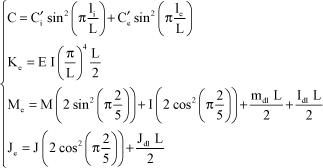
The system has the geometric data defined in Figure 4.36.
Figure 4.36. Modeling of a Rotor Disk and Shaft

For the rotor disks, take:
[4.69] 
For the shaft:
[4.70] 
As the bearings are located at the bending vibration nodes, they induce no external damping. Only external damping caused by external actions (gases) has been considered.
Then we show that:
[4.71] 
Stability criterion [4.62] thus becomes:
[4.72] 
The instability appearance speed is below the operating speed (23,000 rpm). The next paragraph shows a solution to prevent this type of problem while maintaining a high rotational speed.
Like all rotating structures, the turbine has rigid modes (deformation is due to connecting components like bearings) and deformation modes of the rotating section (bending mode for our concern), Figure 4.37.
Figure 4.37. Modeling of a Shaft and Associated Rotor With Bearings

Optimization of the shaft line consists in determining the structure parameters in order to position the operating speed range between the rigid body modes and the first bending mode [EHR 99, VAN 88].
This has several advantages:
– in practice, this arrangement provides a large operating speed range free from any vibration resonance;
– this approach offers the possibility of preventing multiplane balancing at high speed since the system usually only requires balancing of the rigid body type at low speed. This may represent a precious advantage for the manufacture and maintenance of a machine series-produced and widely used;
– provided that the system is not required to be used at the first critical bending speed or close to it, this arrangement enables roller bearings to be used while avoiding complications resulting from addition of bearing dampers.
Figure 4.38. First Three Shaft Modes

Positioning of the critical speeds of rigid body modes Ω1 and Ω2 is also important.
For a turbine, they are usually positioned before the machine operating area, Figure 4.39.
It will be necessary to check that the vibrating motion amplitude, upon changing from the rigid modes to the starting phase, is compatible with bearing operation.
In order to adjust these rigid frequencies and the structure external damping, it is possible to insert a deformable component between the bearing outer ring and the frame so as to adjust the eigenfrequencies of the system (squirrel cage) and a Squeeze Film Damper (SFD) which, during the relative motions, will provide the system with the necessary damping, Figure 4.40.
Figure 4.39. Positioning of Eigenmodes

Figure 4.40. Squirrel Cage Damping System and Squeeze Film Damper - Schematic Diagram

Sizing of the squirrel cage is essential. Excessively rigid, it will act as a recess; excessively flexible, the SFD rings may contact each other and transmit the forces to the frame. The squirrel cage acts as stiffness in series with the bearing stiffness, Figure 4.41.
Figure 4.41. Schematization of Squirrel Cage

In practice, 30% of the absolute displacements of the shaft are expected to be due to the bearing (z2), and 70% to the deformable component (z1). The cage motions in relation to the frame must be great to make the damping effect significant. To this end, the value of K1 is determined to obtain such a distribution.
Whole deformation Δz is equal to:
[4.73] 
That is, the following objective:
[4.74] 
As the springs are in series, equivalent stiffness K is given by:
[4.75] 
That is:
[4.76] 
That is:
[4.77] 
There are limits not to be exceeded for damping. If damping is excessive, the damper is considered as rigid and transmits all forces to the frame. In the contrary case, if it is too low, its efficiency is nil. The elements to be considered are:
– length: L,
– inside diameter: D,
– radial clearance (film thickness): c,
– oil viscosity: μ,
– oil density: ρ.
Figure 4.42. Method to Provide External Damping – SFD System

Experience allows for the definition of technological criteria as regards the choice of some parameters. Thus:
– the geometric parameters of the damper are dependent on the turbine. The dampers are usually of small lengths such that L/D <0.5;
– the clearance between the bearing and the outer ring must be very low to limit the effect of inertia and air ingestion: c < 0.25 mm typically;
– the lubricating oil present in the engine will be used as far as possible to obtain the damping film. This oil has a kinematic viscosity of 3 cSt at 60°C and a density of 950 kg/m3.
All these requirements provide an initial base to calculate the damping coefficients for each type of damper. Other requirements would also have to be considered, specially as regards feasibility, maintenance and cost.
Figure 4.43 indicates the damping coefficient values as a function of eccentricity.
Figure 4.43. Damping Versus Eccentricity
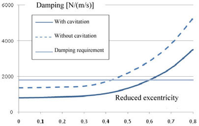
As previously indicated, damping generated by the SFD is between the results obtained with cavitation and without cavitation. Fixed damping is sought but SFD damping depends on eccentricity; optimum damping is reached between 0.57 and 0.75. It is essential to know whether sufficient eccentricity can be reached to obtain the desired damping.