2
ELEMENT B: SHELL
INTRODUCTION
In the last analysis, everything turns as much on exactly how something is realized as on an overt manifestation of its form. This is not to deny spatial ingenuity but rather to heighten its character through its precise realization. Thus the presencing of a work is inseparable from the manner of its foundation in the ground and the ascendency of its structure through the interplay of support, span, seam, and joint—the rhythm of its revetment and the mod- ulation of its fenestration.
—Kenneth Frampton, Studies in Tectonic Culture: The Poetics of Construction in Nineteenth and Twentieth Century Architecture
This chapter on the shell of a building—the structure rising from the foundation; the exterior walls with doors, windows, louvers, and shading; the roof with openings and lights—describes what, arguably, are the most significant architectural form-givers and expressive elements. As Frampton points out in the epigraph here, the realization of the individual components and their interplay is as important as the overall spatial concept.
The information contained in this chapter is meant to serve as the starting point for an exploration of the poetic and tectonic expression of a building’s shell, in concert with its environment, rather than against it, to provide for human occupancy while elevating the emotional and spiritual experience.
In addition to the requirements to be warm and dry, humans need protection from a variety of natural and cultural vicissitudes. In 1963, in
Canadian Building Digest, Dr. Neil Hutcheon categorized the purposes of architectural enclosure, which are paraphrased as follows:
• Control heat flow.
• Control airflow.
• Control water vapor flow.
• Control rain penetration.
• Control light, solar, and other radiation.
• Control noise and vibration.
• Control fire.
• Provide strength and rigidity (resist gravity, snow, wind, seismic, blast, impact, and ballistic loads).
• Be durable.
• Be of economic value.
• Be of aesthetic value.
Satisfying the requirements to be warm, safe, and dry is only the beginning, however; without appealing to the human intellect and addressing sociocultural conditions, mere building results. For architecture to occur, poetics and art must be brought into the realization of the enclosure. Therefore, the last purpose listed is the key to the creation of architecture.
Frampton points out the other determinants with tectonics: the type and topos (or the function or commodity, and the site). The enclosure mediates two distinct environments: the interior and the exterior. The building type is a major determinant in the required interior environment, while the topos—the site and its distinct local climatic conditions—determines the exterior environment. The consideration of these two environments is essential to the architectural solution, and their impact is evident throughout the chapter.
Architecture is not a collection of standard details, but neither is it a maquette assembled without regard for the realities of service and function. Whether a building is expressive of its tectonics or tells a story based on other aesthetic and cultural aspirations, it must provide the basics of support and environmental control over time. Certainly, many details contained in this chapter represent tried-and-true solutions to common problems, but the underlying principles of their functionality have been given in hopes of expanding, modifying, and adapting their usage to inform and influence the overall design concept.
Contributor:
David Altenhofen, AIA, Hillier Archiecture, Philadelphia, Pennsylvania.
DESIGN CONSIDERATIONS
CLIMATE AND ENERGY
Of primary importance to the shell of a building is the mediation between the exterior and interior environment. Proper design and detailing of the building enclosure requires an understanding of the specific characteristics of both the desired interior environmental conditions and specific exterior environmental conditions, on both a macro and micro scale.
DEFINITIONS
When reading the content of this chapter, keep in mind the following definitions of concepts and principles:
• Air barriers: Materials or combinations of materials that form a continuous envelope around all sides of the conditioned space to resist the passage of air. Joints, seams, transitions, penetrations, and gaps must be sealed. The air barrier must be capable of withstanding combined positive and negative wind load and fan and stack pressure without damage or displacement. The air barrier must be at least as durable as the overlying construction and be detailed to accommodate anticipated building movement. An air barrier may or may not be a vapor retarder.
• Vapor barriers and retarders: Without industrywide consensus, materials with a perm rating less than 1 are interchangeably called vapor barriers or vapor retarders (IBC and IEC 2003 use “vapor retarder”). More important than the term is to understand a few basic principles:
• Vapor diffusion through materials with perm ratings less than 1 is nearly inconsequential, but even small gaps or holes can easily transport many times as much water vapor.
• All materials have some greater or lesser degree of resistance to diffusion, and their placement in an enclosure assembly, whether intended as a retarder or not, will affect wetting and, more importantly, drying of an assembly.
• Insulation: A material that slows the flow of heat through conduction.
• Radiant barriers: A material, usually metallic or shiny, that reflects radiant thermal energy.
• Weather barrier (water-resistant barrier): A material that is resistant to the penetration of water in the liquid state, or is waterproof. It may or may not be an air barrier or vapor retarder. The face of the weather barrier is sometimes called the drainage plane.
• Barrier wall: A wall assembly that resists moisture with a continuous waterproof membrane or with a plane of weather barrier material thick enough to prevent absorbed moisture from penetrating to the interior.
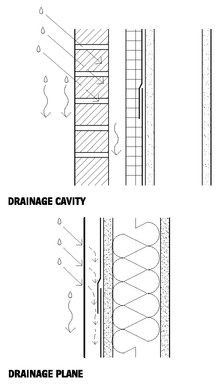
• Drained cavity wall: A wall assembly with an outer water-shedding layer over an air cavity, and with a weather barrier. The cavity is flashed and weeped to drain incidental water.
• Drainage plane wall: A wall assembly with a continuous water-resistant barrier under an outer water-shedding layer. The lack of a cavity limits the amount of water that can be quickly drained.
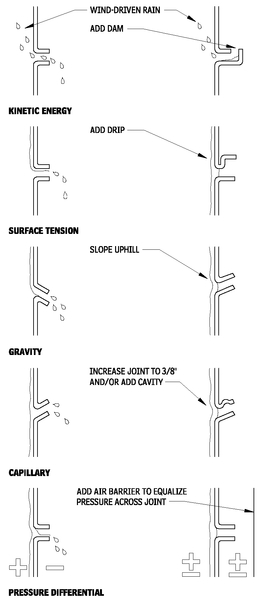
• Pressure-equalized rainscreen wall: A wall assembly that resists all the physical forces that can transport water across a joint in the outer or “rainscreen” layer. Kinetic energy forces are controlled by venting a cavity behind the rainscreen and, thus, allowing the pressure differential across the joint to be equalized. An air barrier and compartmentalization of the cavity are required to control the pressure equalization. The cavity is flashed and weeped to drain incidental moisture.
EXTERIOR CLIMATIC INFLUENCE
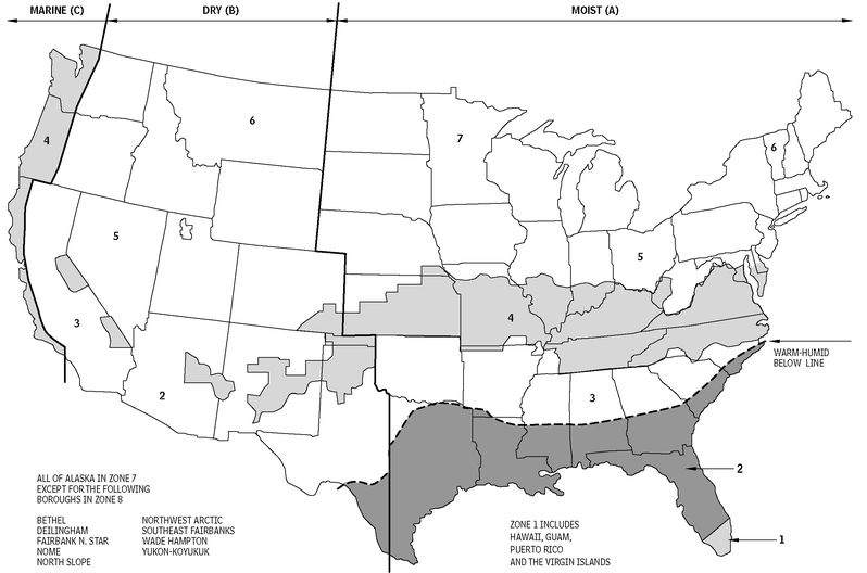
The United States has widely varying climates. More than the obvious extremes of Miami and Alaska are the subtler—and just as important variations—within the contingent states. The ANSI/ ASHRAE/IESNA Standard 90.1 Map of Climate Zones for the United States reproduced in Figure 2.1 dictates zones based on heating and cooling requirements. (Note: A simplified map of climatic zones can be found in the book, Moisture Control Handbook: Principles and Practices for Residential and Small Commercial Buildings, by Joseph W. Lstiburek and John Carmody, 1996.) There are six zones within the continental states and Hawaii, plus two more for Alaska. Within these zones are subzones for moist, dry, marine, and warmhumid.
CLIMATE ZONES FOR UNITED STATES LOCATIONS
2.1
Source: ANSI/ASHRAE/IESNA Standard 90.1
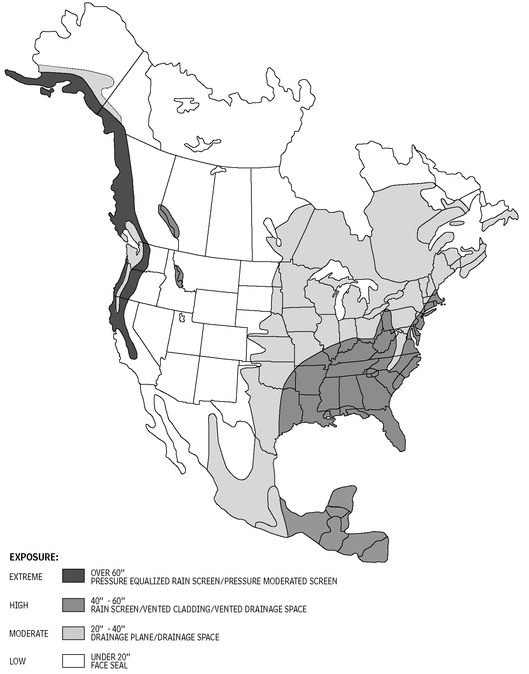
As this chapter will demonstrate, solutions appropriate for one zone may be totally unsuited for another. SEI/ASCE 7, “Minimum Design Loads for Buildings and Other Structures,” and other similar standards establish the wind, snow, and seismic structural loads on buildings. Again, there is wide variation in wind speed, snowfall, and ground movement. In addition to the base loads, localized conditions such as surrounding topography and adjacent buildings can cause wide variances in the environmental influences. Figure 2.2 shows the annual precipitation for North America. Suggested types of exterior enclosure systems that will meet the minimum level of service and reliability are correlated to the rainfall levels.
INTERIOR CLIMATIC INFLUENCE
Environmental conditions to be maintained within the building also influence the design of the shell. Buildings with requirements for high or low levels of humidity, tight temperature tolerances, pressure differentials to the exterior, high-reliability containment, acoustic isolation, protection from blast or forced entry, high indoor air quality, or other extraordinary requirements will require particular attention to system selection and detailing, in concert with consideration of the exterior climate.
ANNUAL PRECIPITATION IN NORTH AMERICA
2.2
Source: ASHRAE Journal, February 2002
HEAT, AIR, AND MOISTURE
In addition to the obvious structural loads, the building enclosure must resist the transfer of heat, air, and moisture (HAM). The laws of physics dictate that heat always flows from hot to cold. Air moves through building enclosures by passing through porous materials, or through holes and gaps in nonporous materials, based on differential air pressures. Moisture, as water in the liquid state (such as rain, snow, and groundwater), moves through enclosures by four methods: capillary action, surface tension, gravity, and kinetic energy (e.g., wind-driven rain). Moisture in the vapor state moves through enclosures from zones of higher to lower vapor pressures, by diffusion through solid materials or by air transport through holes.
CONTROL OF HAM
Control of the flow of HAM across the building enclosure is an interrelated problem, in that air movement can create the kinetic energy that pulls water through joints, dramatically reduce thermal insulation effectiveness, or cause massive vapor transport. Improper thermal insulation can cause condensation on uncontrolled surfaces.
To control HAM, three components must be considered separately: heat, air, and moisture.
Heat is most commonly controlled by thermal insulation. Keep in mind the following:
• Air movement around thermal insulation can seriously degrade its effectiveness, so avoid systems that ventilate the conditioned side of the thermal insulation.
• Radiant barriers may be effective, particularly in hot climates, but they must have an airspace on the warm side. Generally speaking, radiant barriers have virtually no insulating value and should not replace but, instead, enhance typical thermal insulation and conductive losses.
• Thermal short circuits can dramatically reduce the U-value of thermal insulation. The most common example is metal studs, which may reduce the effective value of thermal insulation between the studs by half.
Air transfer is controlled by a coordinated and continuous system of air barriers for all six sides of the enclosure (i.e., the lowest grade level, foundation walls, exterior walls, and the roof).
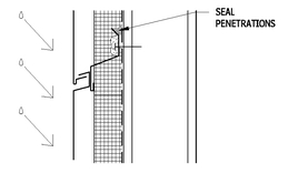
• Common approaches to wall air barriers are continuous membranes applied to sheathing and sealed to windows, doors, and penetrations.
• Below-grade assemblies can utilize either the concrete walls and slabs or applied waterproofing membranes.
• Most typical low-slope roof membranes will provide an air barrier, except for mechanically fastened systems that may not be able to resist all of the required loads.
• It is possible to design the gypsum board as an air barrier, if all joints and cracks are sealed.
• Many air barrier systems require a combination of a membrane and a structural panel to resist loading, such as spun-bond polyolefin membranes stapled to sheathing or bituminous membranes adhered to CMU.
Moisture management consists of controlling moisture entry, moisture accumulation, and allowing for drying.
• Perfect barriers to moisture are virtually impossible to achieve; therefore, it is important that measures taken to keep out moisture do not also trap moisture—for example, waterproofing membranes that trap thermal insulation between a vapor retarder.
• It is essential to maintain a balance of the moisture that is able to accumulate in an assembly between drying cycles. Accumulation and drying are extremely dependent on the local climate. Some materials such as wood-framed walls and masonry have the capacity to absorb relatively large quantities of moisture and to then later dry out without damage or deterioration. Other systems such as gypsum board on metal studs have very little capacity for the storage of moisture.
• The source of water is primarily rain, which should be limited by a reasonably detailed assembly based on the expected amount of precipitation. The precipitation map in Figure 2.2 shows recommended enclosure types along with the required performance to minimize water entry.
• Below grade, the primary source of moisture is through capillary action that can be controlled through membranes and capillary breaks.
• Sources of vapor may be in the interior or exterior environment. Vapor retarders have been the traditional method used to control vapor movement, but their use in mixed heating and cooling climates must be carefully evaluated to allow drying.
• Moisture control in the solid state (i.e., ice) depends on not letting liquid water freeze; or, if it does, allowing room for expansion. For example, cold roof surfaces that eliminate thawing also prevent ice buildup, and air-entrained concrete provides room for ice crystals to expand.
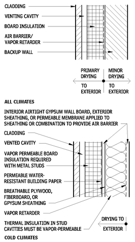
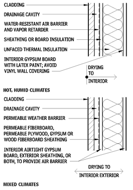
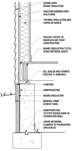
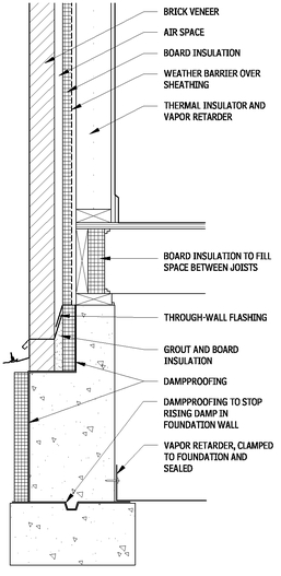
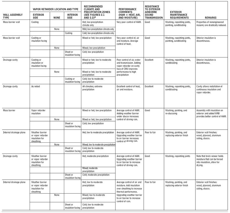
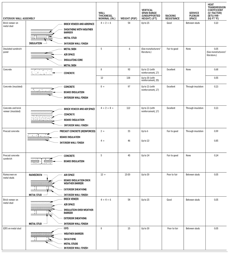
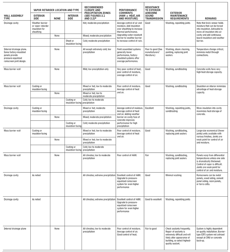
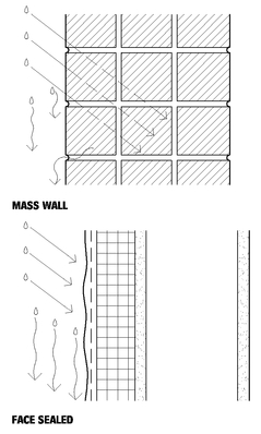
Figures 2.3 and 2.4 show details of wall assemblies that can be used for analysis of drying under various climatic conditions. The various assemblies are somewhat independent of the cladding type. Other wall assemblies, including face-sealed or massive barrier assemblies, should receive similar analysis of HAM control. Two useful tools for this purpose are:
•
Computerized modeling of wetting and drying of walls: This is widely available and is very helpful to understanding moisture accumulation and drying. Analysis is recommended for large projects and any assembly that requires seasonal drying. Mixed climates may be the most difficult to predict by rule of thumb or empirical analysis. WUFI, developed by the Fraunhofer Institute for Building Physics in Germany with a North American version developed jointly with Oak Ridge National Laboratory (
www.ornl.gov) is widely recognized modeling tool. Similar software is available through
www.virtual-north.com/download/OrderForm.pdf and
www.architects.org/emplibrary/HAMtoolbox.pdf.
• Manual analysis of simple two-dimensional diagrams of wall sections: This involves using temperature gradients plotted against dew point temperature or vapor-pressure gradients plotted against saturation pressure. For instructions refer to “Design Tools,” by Anton TenWolde (Chapter 11 in the manual Moisture Control in Buildings [MNL18], Heinz R. Trechsel, editor, published by ASTM, 1994).
CONSIDERATIONS FOR CLIMATE ZONES
GENERAL
• Refer to specific information for each material for more information regarding selection criteria and proper detailing.
• Include only one vapor retarder in a wall assembly, and ensure that all other materials are increasingly permeable from the vapor retarder out.
• It is acceptable (and sometimes desirable) to provide more than one air barrier in a wall assembly.
• It is generally desirable to protect blanket insulation from airwashing with an air barrier on the cold side.
ALL CLIMATES
• Highly reliable enclosure system to control HAM in all climate zones, without relying on building mechanical systems to dry interior air.
• Thermal insulation located outside of structure and wall framing allows easy installation of continuous air barriers and vapor retarders.
• Thermal insulation must be continuous to prevent the vapor retarder from reaching the dew point.
• Excellent choice for masonry veneer over CMU or metal stud backup systems.
• If metal stud backup systems are used, do not place thermal insulation between the studs.
• Any paint or wall covering is allowed on interior finish.
COLD CLIMATES (Zones 5 to 8)
• Materials should be progressively more permeable, because they are located closer to exterior face.
• Any paint or wall covering is allowed on interior finish.
• Mechanical system is not required to dry interior air.
• Failure of the building paper may allow moisture accumulation that cannot be overcome by drying.
• Elements penetrating thermal insulation, (such as beams supporting a projecting canopy or the sump pan of roof drains) can cause condensation problems, unless they are insulated with closed-cell thermal insulation or a thermal insulation with a vapor retarder to keep moisture-laden air from getting to these surfaces. This is particularly true for occupancies with high humidity, (including residences, hospitals, museums, swimming pools,).
ALL CLIMATES AND COLD CLIMATES
2.3
HOT CLIMATES (Zones 1, 2, and 3)
• The mechanical system must provide dehumidification of interior air for drying.
• Avoid any vapor-impermeable interior finishes (e.g., a vinyl wall covering that will trap moisture).
• A radiant barrier may be incorporated into the cavity.
• Taped joints in sheathing, board insulation, or a combination may provide air barrier.
• An air barrier is crucial to limit moisture transport through imperfections in the vapor retarder.
MIXED CLIMATES (Zones 3 and 4)
• All materials must be relatively vapor-permeable to allow drying in both directions, because seasons change direction of heat flow and vapor drive.
• Detail system with interior and exterior side-permeable air barriers to limit moisture transport and infiltration/exfiltration.
• May be possible to use board insulation with taped joints as sheathing, which will form a vapor retarder if board and blanket insulation have approximately the same U-value.
SUSTAINABILITY AND ENERGY
The building shell should be a major part of the sustainable strategy. At a minimum, the shell should:
• Contribute to minimizing energy usage.
• Incorporate environmentally sensitive materials.
HOT, HUMID CLIMATES AND MIXED CLIMATES
2.4
• Ensure good indoor air quality and occupant comfort.
• Be durable.
For high-performance building projects, the enclosure could help generate energy, return nutrients to the environment, and filter pollutants.
One area of special concern for the building shell is durability, even though it currently is not included in LEED evaluations in the United States. (It is included in Canadian LEED programs). The building superstructure and enclosure are frequently portions of the building that should last the longest and are the most difficult to repair or replace. Buildings that perform well for many years slow or reduce the consumption of resources and the wastestream. Failures of the enclosure can lead not only to water-damaged materials needing repair or replacement but also to unnecessary long-term energy consumption, toxic mold, and sick buildings.
Buildings are major consumers of energy, so the enclosures should be part of a strategy to reduce energy consumption. In fact, creating a well-performing enclosure is considered to be the first step in reducing energy usage, ahead of other more sophisticated strategies, such as high-performance mechanical systems. A thorough understanding of the interior and exterior environments is paramount. For residential buildings in cold climates, heat loss through the enclosure may be the largest component of total energy consumption. For large commercial buildings in a moderate environment, daylighting schemes may save more energy, even as they may result in an enclosure with lower thermal resistance.
Most jurisdictions require compliance with an energy conservation code. ASHRAE 90.1 and the International Energy Code (in various editions) are common model codes. These minimum standards should be exceeded by 20 to 50 percent, if possible.
Consult the following references:
• Designing the Exterior Wall: An Architectural Guide to the Vertical Envelope by Linda Brock (John Wiley & Sons, Inc., 2005)
• Moisture Control Handbook: Principles and Practices for Residential and Small Commercial Buildings by Joseph W. Lstiburek and John Carmody (John Wiley & Sons, Inc. 1996)
• Water in Buildings: An Architect’s Guide to Moisture and Mold by William B. Rose (John Wiley & Sons, Inc., 2005)
NOTES
2.3 and 2.4 Provide an air barrier in the assembly at one or more of the locations noted by properly detailing either the inner layer of gypsum board, the sheathing layer, or the permeable weather barrier. The inner gypsum board can be made an air barrier by sealing the perimeter, penetrations, and transitions to adjacent air barrier assemblies. The sheathing can be made an air barrier through similar means of sealing all joints, penetrations, and transitions. Using a membrane over the sheathering (either fluid-applied or sheet material) that is vapor permeable, weather-resistant, anmd airtight is extremely effective for providing an air barries with the added benefits of simple installation and inspection.
SUPERSTRUCTURE
FLOOR CONSTRUCTION
This section of the chapter examines common floor construction assemblies. Consult literature from manufacturers and trade associations for more details on the information presented in the accompanying tables.
FLOOR STRUCTURAL FRAME
CONCRETE CONSTRUCTION
The information presented here is intended only as a preliminary design guide. All structural dimensions for slab thickness, beam and joint sizes, column sizes, should be calculated and analyzed for each project condition by a licensed professional engineer.
Spans shown in the accompanying figures and tables are approximate and are based on use of mild reinforcing steel. For spans greater than 40 ft, consider post-tensioning.
Consider embedded items such as conduits and penetrations for ducts and pipes when coordinating a structural system. Concrete floor construction may have less flexibility for locating large duct openings close to beam lines or small penetrations immediately adjacent to columns.
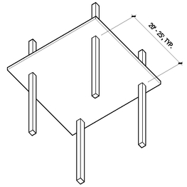
FLAT PLATE
2.5
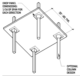
FLAT SLAB
2.6
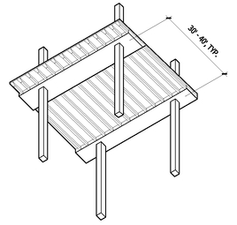
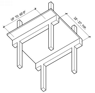
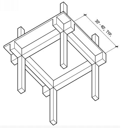
BANDED SLAB
2.7
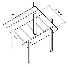
JOIST SLAB
2.8
SKIP JOIST
2.9
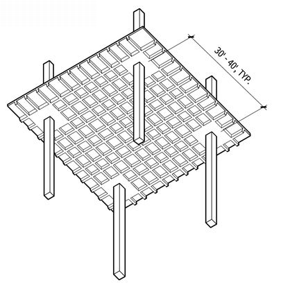
WAFFLE SLAB
2.10
ONE-WAY SLAB
2.11
TWO-WAY SLAB
2.12
Contributor:
Russell S. Fling, PE, Columbus, Ohio.
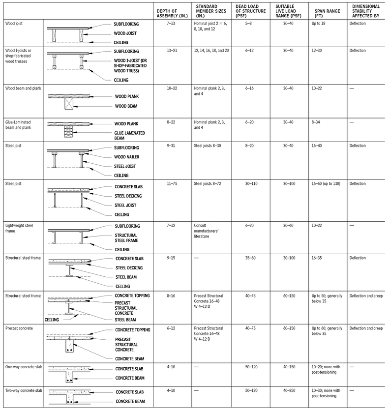
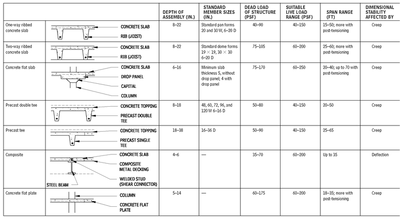
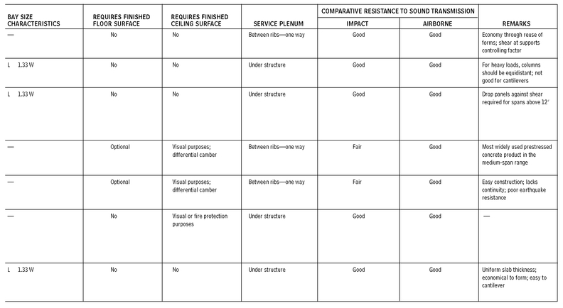
FLOOR STRUCTURE ASSEMBLIES
2.13
Contributors:
Roger K. Lewis, FAIA, and Mehmet T. Ergene, architect, Roger K. Lewis & Associates, Washington, DC.
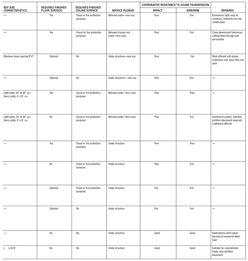
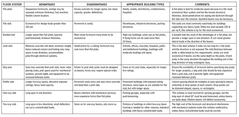
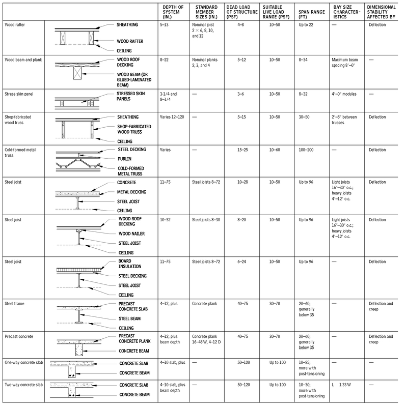
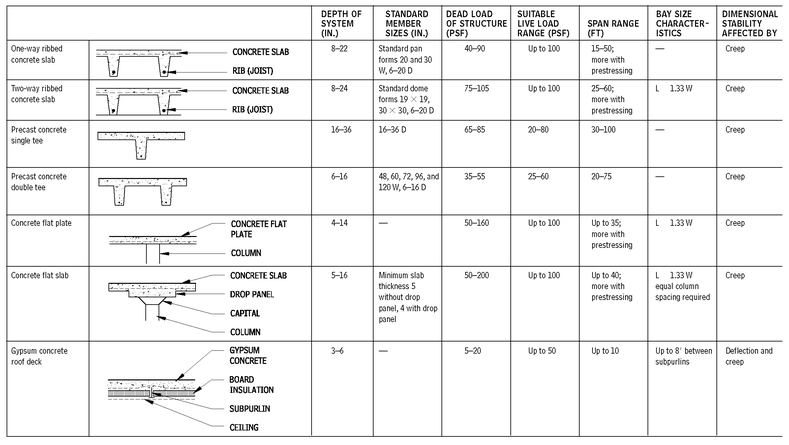
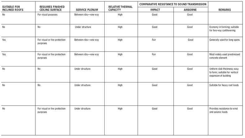
CONCRETE FLOOR SYSTEM COMPARISON
2.14
Contributors:
Russell S. Fling, PE, Columbus, Ohio; Roger K. Lewis, FAIA, and Mehmet T. Ergene, architect, Roger K. Lewis & Associates, Washington, DC.
PRESTRESSED AND POST-TENSIONED CONCRETE
Concrete by itself is inherently strong in tension and weak in compression. There are two procedures used for placing concrete in compression. Prestressing of the reinforcing steel occurs prior to placement of concrete and is used almost exclusively with precast concrete. Post-tensioning is the permanent tensioning of reinforcing steel for cast-in-place concrete.
• Concrete strength is usually 5000 psi at 28 days, and at least 3000 psi at the time of post-tensioning. Use hard-rock aggregate or lightweight concrete. Low-slump-controlled mix concrete is required to reduce shrinkage. Concrete shrinkage after post-tensioning decreases strength gains.
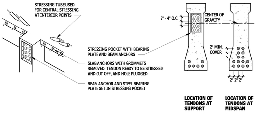
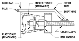
• Post-tensioning systems can be divided into three categories depending on whether the tendon is wire, strand, or bar. Wire systems use 0.25-in. diameter wires that have a minimum strength of 240,000 psi, and are usually cut to length in the shop. Strand systems use tendons (made of seven wires wrapped together) that have a minimum strength of 270,000 psi, and are cut in the field. Bar systems use bars ranging from 5/8- to 13/8-in. diameter, with a minimum strength of 145,000 psi, and may be smooth or deformed. The system used determines the type of anchorage used, which in turn affects the size of blockout required (in the edge of slab or beam) for the anchorage to be recessed.
• Grease and wrap tendons, or place in conduits, to reduce frictional losses during stressing operations. Limit the length of continuous tendons to about 10 ft if stressed from one end. Long tendons require simultaneous stressing from both ends to reduce friction loss. Tendons may be grouted after stressing, or left unbonded. Bonded tendons have structural advantages that are more important for beams and primary structural members.
• Minimum average post-tensioning (net force per area of concrete) equals 150 to 250 psi for flat plates and 200 to 500 psi for beams. Exceeding these values by much causes excessive posttension loss because of creep.
POST-TENSIONING ANCHOR
2.15
• Field inspection of post-tensioned concrete is critical to ensure proper size and location of tendons, and to monitor the tendon stress. Check tendon stress by measuring the elongation of the tendon and by monitoring gauge pressures on the stressing jack.
• Make provisions for the shortening of post-tensioned beams and slabs caused by elastic compression, shrinkage, and creep. After the post-tensioning is complete, build shear walls, curtain walls, or other stiff elements that adjoin post-tensioned members and isolate them with an expansion joint. Otherwise, additional post-tensioning force will be required to overcome the stiffness of the walls and prevent cracking.
• Fire tests have been conducted on prestressed beam and slab assemblies according to ASTM E 119, “Standard Test Methods for Fire Tests of Building Construction and Material,” test procedures. They compare favorably with reinforced cast-in-place concrete. There is little difference between beams using grouted tendons and those using ungrouted tendons.
PRESTRESSED OR POST-TENSIONED BEAM
2.16
Contributor:
Leo A. Daly, Planning/Architecture/Engineering/Interiors, Omaha, Nebraska.
Consult the following references:
• Post-Tensioning Institute, Post-Tensioning Manual.
• Precast/Prestressed Concrete Institute, PCI Design Handbook - Precast and Prestressed Concrete.
• Design of Prestressed Concrete Structures, 1981, T.Y. Lin and Ned H. Burns, Wiley
• American Concrete Institute, Building Code Requirements for Structural Concrete and Commentary (ACI-318)
When working with a prestressed or post-tensioned beam, keep the following in mind:
• Prestressing force compresses the entire cross section of the beam, thereby reducing unwanted tension cracks.
• Permanent tension is introduced into the tendon and “locked in” with the stressing anchorage in one of two ways, though the principle in both cases is the same. In prestressed concrete, the tendon is elongated in a stressing bed before the concrete is poured. In post-tensioned concrete, the tendon is elongated after concrete has been poured and allowed to cure by means of hydraulic jacks pushing against the beam itself. Post-tensioned beams permit casting at the site for members too large or heavy for transporting from the factory to the site.
• Internal vertical forces within the beam are created by applying tension on the tendon, making the tendon begin to “straighten out.” The tension reduces downward beam deflection and allows for shallower beams and longer spans than in conventionally reinforced beams.
• Auxiliary reinforcing steel provides additional strength, and controls cracking and produces more ductile behavior.
• Use stirrups to provide additional shear strength in the beam and to support the tendons and longitudinal reinforcing steel. Stirrups should be open at the top to allow the reinforcing to be placed before the tendon is installed. After the tendons are placed, “hairpins” that close the stirrups may be used, when required.
POST-TENSIONED CONCRETE BEAM AND SLAB
2.17
UNBONDED SINGLE-STRAND TENDON INSTALLATION AT SLAB
2.18
Contributor:
Leo A. Daly, Plan ning/Architecture/Engineering/Interiors, Omaha, Nebraska.
UNBONDED SINGLE STRAND TENDON ANCHORAGE
2.19
GROUTED THREAD BAR ANCHORAGE
2.20
PRECAST CONCRETE FRAME
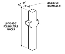
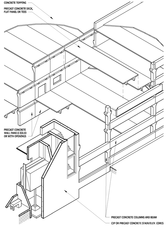
Precast concrete frame systems are ideal for highly repetitive structural frames such as parking garages and hotel/apartment/dormitory buildings. Precast concrete members can be precast structural concrete or precast architectural concrete in exposed locations.
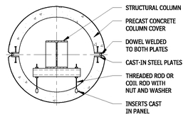
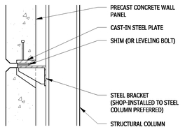
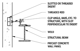
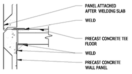
Detailing of connections for both aesthetics and to protect embedded steel members from corrosion is crucial. Typically, welded or bolted connections are grouted after final adjustment and anchorage.
Using shear walls in both directions is the most common method to resist lateral loads. Stair/elevator cores and dwelling unit separation may also serve as shear walls.
PRECAST CONCRETE COLUMN
2.21
PRECAST CONCRETE FRAME
2.22
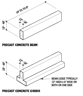
PRECAST CONCRETE BEAM AND GIRDER
2.23
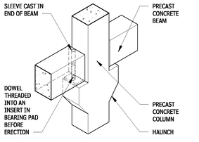
DOWELED BEAM-TO-COLUMN CONNECTION
2.24
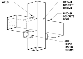
BEAM-TO-HAUNCHED COLUMN CONNECTION
2.25
NOTES
2.24 The beam sits on the bearing pad, which provides uniform bearing and accommodates small movements caused by shrinkage, creep, and temperature changes.
2.25 Steel haunches are smaller than concrete bearing pads, which is important if headroom is critical.
Contributor:
Richard J. Vitullo, AIA, Oak Leaf Studio, Crownsville, Maryland.
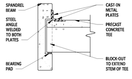
SPANDREL CONNECTION
2.26
STRUCTURAL STEEL FRAMING
MOMENT-RESISTING FRAME
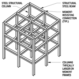
A moment-resisting frame’s lateral stability and resistance to wind and seismic forces depend on a fixed connection of beams and columns. A moment-resisting connection is achieved when the top and bottom flanges of each beam are welded to the flanges of the connecting columns with full-depth welds. By directly welding the beam web to the column flange, the beam’s horizontal reaction to wind forces is transferred to the column. (A connection using web angles and high-strength bolts is also permitted.) The building’s floors are designed to act as diaphragms that connect all of the columns and beams, enabling the building to react as a unit.
Moment-resisting frames are uneconomical in tall steel buildings because the larger lateral forces in such structures can be handled more efficiently by compression and tension diagonal members, as found in braced frames. To save costs, often the upper stories of a braced-frame building use moment-resisting beam-column connections to resist wind loads.
MOMENT-RESISTING FRAME
2.27
BRACED CORE
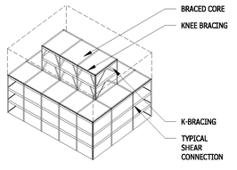
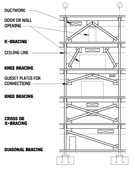
In the braced core system, walls around elevator shafts and stairwells are designed to act as vertical trusses that cantilever up from the foundation. The chords of each truss are building columns; the floor beams act as ties. Diagonals placed in a K pattern (occasionally, in an X pattern) complete the truss. A system employing knee braces is used in seismic areas because of its greater capability to dissipate earthquake energy.
Braced core systems can be used efficiently in single-story buildings, as well as in buildings over 50 stories.
BRACED CORE
2.28
BRACING DIAGRAM
2.29
Following are characteristics and principles to keep in mind when working with structural steel framing:
• The high strength of steel provides for economical construction of relatively large structural bays.
• Major framing elements are typically W-shaped sections, or round, square, and rectangular hollow structural sections. Angles or channels may be used for architectural expression.
• Building codes require protection of the steel from fire, except for small or low-rise structures in some low-hazard occupancies.
• Horizontal loads from wind and seismic events must be resisted, typically by diagonal bracing, moment connections, or shear walls.
• Moment frames allow maximum floor plan flexibility, but typically increase weight and cost of the structural steel framing.
• Braced frames are cost-effective, but disrupt the floor plan if not carefully located around typical core elements such as stairs, shafts, and toilet rooms. Bracing typically is provided by angles or W-shapes, as well as hollow structural shapes. Rods and cables may be used for architectural expression.
• Shear walls, typically around shafts for stairs, ducts, and elevators, can be an effective lateral load design option. Shear walls can be constructed of steel plate, concrete, or reinforced CMU. Minimize openings in shear walls for doors and services.
• It may be effective to mix different lateral restraint methods. For a long, narrow building, bracing in the short direction with moment frames in the long direction may be effective.
• The floor or roof deck typically is designed to act as a diaphragm to transmit loads to the lateral restraint elements. Structures without a deck capable of transmitting loads (such as bar grating or metal roofing) may require diagonal bracing in the floor or roof framing.
• Open-web steel joists may be used within a main frame of structural steel for economy.
For more information, refer to the AISC Manual of Steel Construction.
FABRICATED FIREPROOFED STEEL COLUMNS
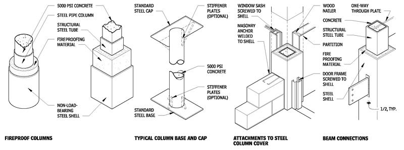
Fabricated fireproofed steel columns, (lally columns) are structural units that consist of load-bearing steel columns filled with concrete. This creates a column with increased load-bearing capacity in a space no larger than a standard column. Lally columns have fire-resistant characteristics when a layer of fireproofing material encases the structural column. Fire ratings typically range from two to four hours.
NOTES
2.28 Bracing design to be determined by structural engineer based on specific loading configurations.
2.29 a. Knee bracing introduces bending into columns and beams and may increase their size, but allows largest openings.
b. Cross or diagonal bracing is very efficient but limits opening location and size.
Contributors:
Donald J. Neubauer, PE, Neubauer-Sohn Consulting Engineers, Potomac, Maryland; Richard J. Vitullo, AIA, Oak Leaf Studio, Crownsville, Maryland.
FABRICATED FIREPROOFED STEEL COLUMNS
2.30
ARCHITECTURALLY EXPOSED STRUCTURAL STEEL FRAMING
The characteristics and principles to keep in mind when working with architecturally-exposed structural steel (AESS) include the following:
• AESS is structural steel superstructure, supporting all or portions of a building, which is left exposed in the finished work. Through layout and detailing, AESS is meant to contribute to the architectural expression.
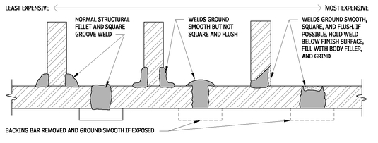
• The challenge to successful use of AESS is to clearly specify and detail the level of quality required, which is substantially beyond the requirements for normal structural steel. Primary areas of concern are the quality of finish of the individual members, the quality of the methods of joining members together (particularly of welds), and the tolerances of the finished work.
• AESS frequently incorporates a variety of tension members fabricated of stainless steel and proprietary fittings.
• AESS may need special fire protection, such as intumescent coating or deluge sprinkler systems.
• For economy, it is worthwhile to carefully identify which portions of the AESS will be viewed in close proximity versus those that are farther away. Locate defects, welds, and connections on the side of assembly away from view, for economy.
Refer to AESS Supplement to “Modern Steel Construction” (May 2003), for explanation of how to specify AESS.
AESS CONNECTION
2.31
AESS WELDS
2.32
NOTE
2.31 Locate HSS seam away from line of sight, or grind smooth.
Contributors:
Anthony Golebiewski, AIA, Kling, Philadelphia, Pennsylvania; Eric Gastier, Alexandria, Virginia.
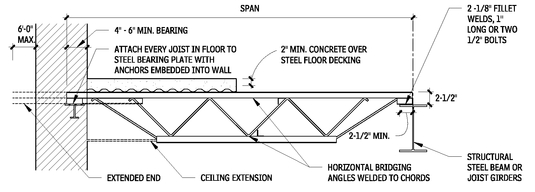
STEEL JOIST FLOOR FRAMING
Design consideration of steel joist floor framing should include:
• Ceilings: Ceiling supports can be suspended from or mounted directly to the bottom chords of joists. Suspended systems are recommended, because of dimensional variations in actual joist depths.
• Floor construction: Joists are usually covered by 2-1/2 to 3 in. of concrete on steel decking. Concrete thickness may be increased to accommodate electrical conduit or electrical /communications raceways. Precast concrete, gypsum planks, or plywood can also be used for the floor system.
• Vibration: Objectionable vibrations can occur in open web joist and 2-1/2-in. concrete slab designs for open floor areas at spans between 20 and 40 ft, in particular at 28 ft. When a floor area cannot have partitions, objectionable vibrations can be prevented or reduced by increasing slab thickness or modifying the joist span. Attention should also be given to support for framing beams, which can magnify a vibration problem when unsupported.
• Openings in floor or roof systems: Small openings between joists are framed with angles or channels supported on the adjoining two joists. Larger openings necessitating interruption of joists are framed with steel angle or channel headers.
• Adaptability: It is more difficult to alter joists, add openings, or change loading than with structural steel framing.
• Fireproofing: Applying fireproofing to joists is more difficult and expensive than to structural steel.
SECTION-THROUGH OPEN WEB STEEL JOIST BEARING
2.33
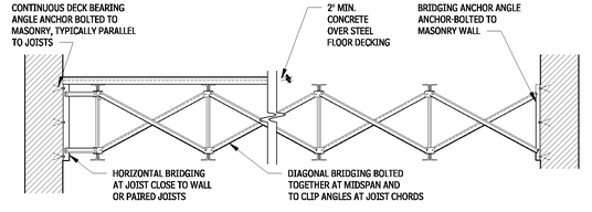
SECTION-THROUGH OPEN WEB STEEL JOISTS
2.34
SECTION-THROUGH LONG SPAN STEEL JOIST BEARING
2.35
SECTION-THROUGH LONG-SPAN STEEL JOIST
2.36
BOTTOM CHORD BEARING AT SQUARE END
2.37
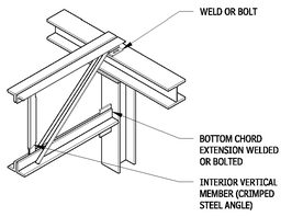
BOTTOM CHORD EXTENSION DETAIL
2.38
NOTE
2.35 Web-member type depends on span and load characteristics.
Contributors:
Kenneth D. Franch, PE, AIA, Aguirre, Inc., Dallas, Texas; Charles M. Ault, Setter, Leach, & Lindstrom, Architects & Engineers, Minneapolis, Minnesota.
COLD-FORMED METAL FLOOR JOIST FRAMING
Cold-formed steel (CFS) floor framing uses C-shaped members that are cold-rolled from a steel sheet. CFS framing is laid out similar to traditional wood joist floor framing. Finishes may be a hot-dipped galvanized coating or shop primed. Fastening is typically selfdrilling, self-tapping screws, or welded.
Final engineering of CFS framing is commonly provided by a structural engineer hired by the installing contractor, based on a performance specification prepared by the architect and project structural engineer. This delivery method, known as delegated design, allows an optimization of the design of the CFS system. CFS framing characteristic vary by manufacturer. Based on preliminary investigation and other project design requirements, the design professional may select certain characteristics of the joists, for example depth or minimum spacing. The installer’s engineer will then select specific joists that conform to the design characteristics that also meet the structural performance criteria, including yield strength (33 or 50 ksi), joist gauge and flange width. CFS rim joists, plates, and other framing may require continuous insulation outside of the CFS element, to reduce thermal bridging and to comply with energy code.
BRIDGING
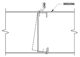
2.39
Joists are subject to twisting under load. Bracing of the top and bottom flange is required at approximately 1/3 points or 6 to 8 ft on center, depending on final design. Bridging is, typically, continuous top and bottom straps with solid blocking at ends, and periodically spaced. Structural sheathing or decking may reduce some or all of the bridging.
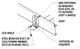
WEB STIFFENERS
2.40
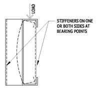
Point loads at bearing points or from applied loads may cause crushing of the flange or folding of the web. Stiffeners from short lengths of a vertical joist, a sistered joist, or angles attached to the rim track may be required, as determined by final engineering.
OPENINGS
2.41
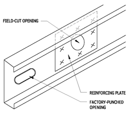
Joists may come factory-punched, with openings of approximately 1-1/2 by 4 in. at 24 in. on center, though this will vary by manufacturer. Additional openings, generally not larger than half the joist depth, may be added if individually analyzed during final engineering. Reinforcing plates may be required.
COLD-FORMED METAL JOISTS
2.42
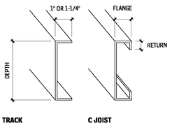
Common Depths: 6, 7-1/4, 8, 9-1/4, 10, 11-1/2, 12, 14, and 16 in., consult manufacturers for available sizes.
Lengths up to 60 ft.
| FLANGE (IN.) | RETURN (IN.) |
|---|
| 1-3/8 | 5/16 to 3/8 |
| 1-5/8 | 1/2 to 9/16 |
| 2 or 2-1/2 | 9/16 to 11/16 |
| 3 or 3-1/2 | 1 |
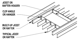
FRAMING OF FLOOR OPENING 2.43
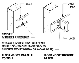
FLOOR JOISTS AT CONTINUOUS WALLS
2.44
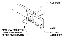
JOISTS OVER BEAM OR BEARING WALL (CONTINUOUS SPAN)
2.45
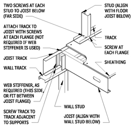
FLOOR FRAMING AT EXTERIOR WALL
2.46
Consult the following reference:
• “Product Technical Information,” the Steel Stud Manufacturers Association (
www.ssma.com)
NOTES
2.44 Provide solid blocking and bridging as required.
2.45 a. Continuous bridging is required between each joist above a beam. Solid blocking in other spaces may be used in lieu of bridging. b. When a bearing wall is above, the studs must align with the joists below.
c. Web stiffeners are not required when continuous solid blocking is used.
Contributor:
American Iron and Steel Institute, Washington, DC.
FLOOR JOISTS SUPPORTED BY BEAM OR BEARING WALL (OVERLAPPED)
2.47
FLOOR JOISTS BEARING ON FOUNDATION
2.48
WOOD FLOOR FRAMING
This section examines the use of wood in floor framing assemblies.
WOOD FLOOR FRAMING MEMBERS
2.49
FLOOR FRAMING WOOD BEAMS
2.50

NOTES
2.47 a. Continuous bridging is required between each joist above a beam. Solid blocking in other space may be used in lieu of bridging.
b. When a bearing wall is above, studs must align with joists below. 2.50 a. Heavy timber beam: Timber beams are available in a variety of species and grades; Douglas fir is the strongest. Heavy timber uses rectangular solid-wood framing members that are a nominally a minimum of 5 in., in both dimensions.
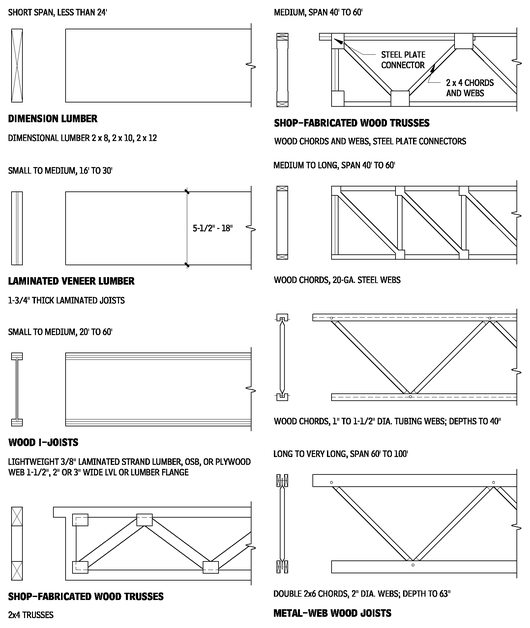
b. Laminated veneer lumber (LVL) beam: Vertical factory-laminated sections are glued together. Actual widths are multiples of 1-3/4 in. (two pieces match thickness of 2 × 4 wall). Actual heights range from 5-1/2 to 18 in.
c. Parallel strand lumber (PSL) beam: Factory-glued composite beam made with long narrow strips of veneer, oriented along beam length. Actual widths are 3-1/2, 5-1/4, and 7 in. Heights range from 9-1/4 to 18 in.
d. Glue-laminated beam: Horizontal factory-glued laminations make a knot-free and very stable beam. Actual widths are 3-1/8, 5-1/8, 7-1/8 in., and so on. Heights are in multiples of 1-1/2 in.
e. Built-up beam: Dimension lumber is nailed together to form a single beam (four pieces maximum). Widths are multiples of 1-1/2 in. Height follows dimension lumber.
f. Flitch beam: A steel plate sandwiched between two pieces of lumber adds strength without substantially increasing the beam size. The lumber prevents buckling of the steel and provides a nailing surface. Widths are 3 to 3-1/2 in. Heights follow dimension lumber.
g. Box beam: 2 × 4 lumber is sandwiched between two plywood skins. Plywood is both nailed and glued to 2 × 4s and at all edges. Plywood joints must be offset.
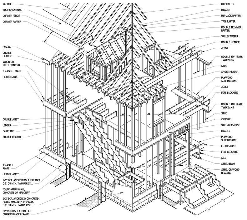
WESTERN OR PLATFORM WOOD FRAMING
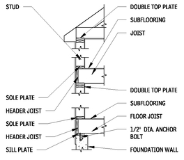
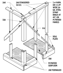
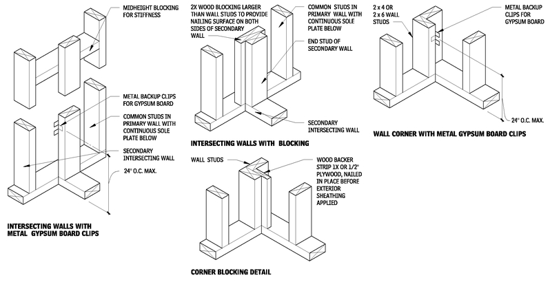
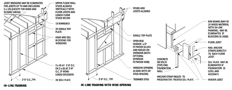
Before any of the superstructure is erected, the first-floor framing and subflooring is put down, making a platform on which the walls and partitions can be assembled and tilted into place. Because floor framing and wall frames do not interlock, adequate sheathing must act as bracing and provide the necessary lateral resistance. Where required for additional stiffness or bracing, metal strapping, or 1 × 4 may be let into the outer face of studs at 45° angles, secured at top, bottom, and to studs. The process is repeated for each story of the building.
Bridging may be omitted when flooring is nailed adequately to the joist. However, where nominal depth-to-thickness ratio of joists exceeds 6, bridging would be installed at 8-ft-0-in. intervals. Building codes may allow omission of bridging under certain conditions. Steel bridging is available. Some types do not require nails. For firestopping, all concealed spaces in framing, with the exception of areas around flues and chimneys, are to be fitted with 2-in. blocking arranged to prevent drafts between spaces.
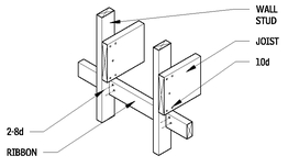
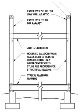
Platform framing has essentially replaced balloon framing. Balloon framing with studs continuous from wood sill to top plate is rarely used, except in special locations (such as two-story spaces, at parapets, and similar situations where a structural cantilever of the wall is required).
PLATFORM FRAMING
2.51
NOTES
2.14 a. Roof framing may be level, I-joist, or trusses, shown in Figure 2.116.
b. Floor joists may be any of the framing members shown in Figure 2.50.
Contributor:
Timothy B. McDonald, Washington, DC.
PLATFORM FRAMING SECTION
2.52
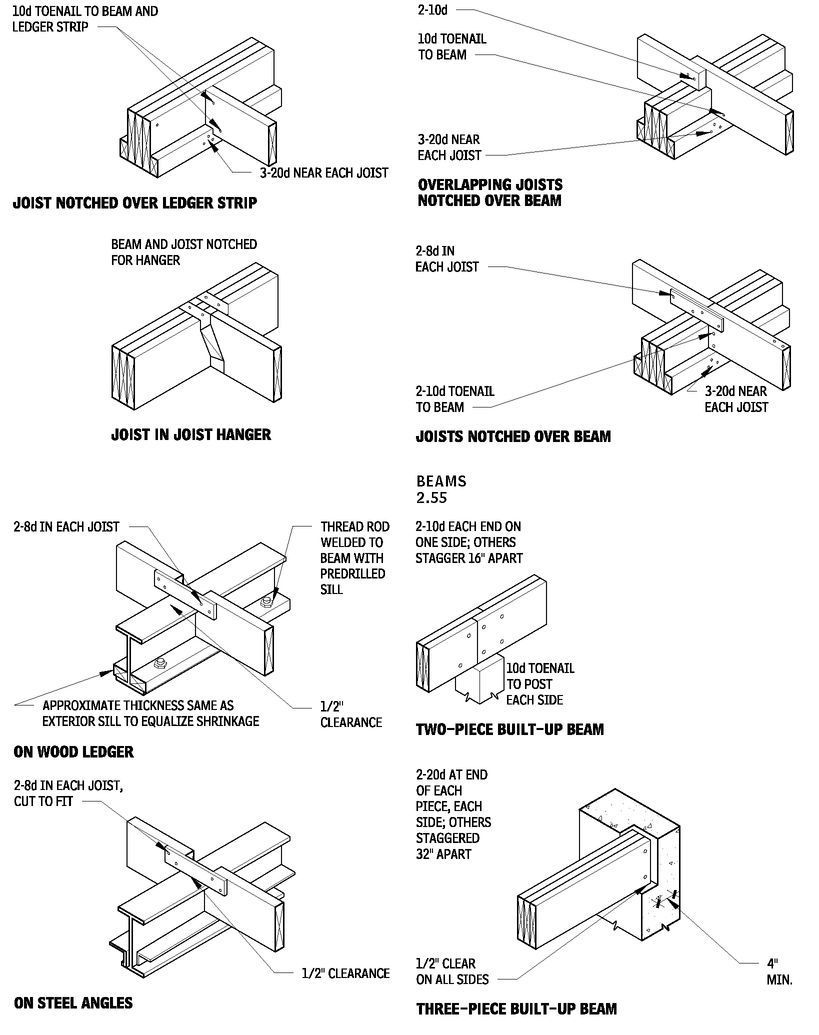
FRAMING DETAILS FOR JOISTS AND SILLS
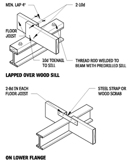
WOOD JOISTS SUPPORTED ON STEEL BEAM
2.53
WOOD JOISTS SUPPORTED ON WOOD BEAM
2.54
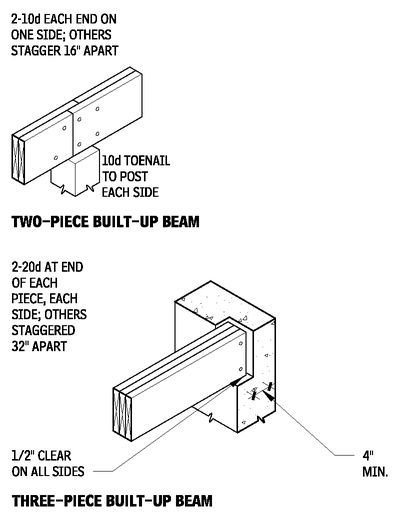
BEAMS
2.55
BRIDGING
2.56
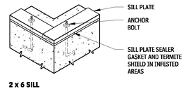
SILL FOR PLATFORM FRAMING
2.57
Contributor:
Joseph A. Wilkes, Wilkes and Faulkner, Washington, DC.
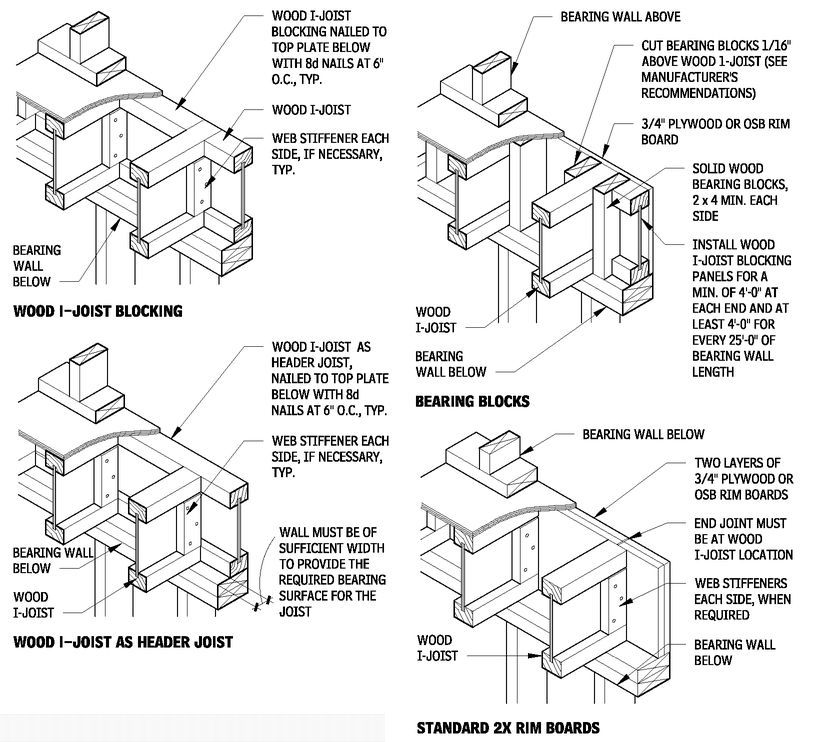
WOOD I-JOIST FLOOR FRAMING DETAILS
2.58
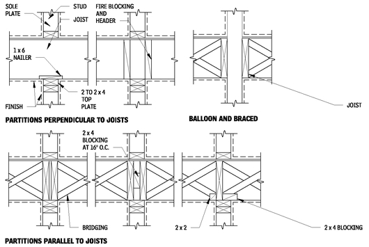
FLOOR DETAILS AT BEARING INTERIOR PARTITION
2.59
Contributors:
Joseph A. Wilkes, Wilkes and Faulkner, Washington, DC; John Ray Hoke, Jr., FAIA, Washington, DC.
FLOOR DETAILS AT NONBEARING INTERIOR PARTITIONS
2.60
FLOOR CANTILEVERS
2.61
NOTE
2.61 a. Any extension greater than 2 must be engineered.
Contributors:
Joseph A. Wilkes, Wilkes and Faulkner, Washington, DC; John Ray Hoke, Jr., FAIA, Washington, DC.
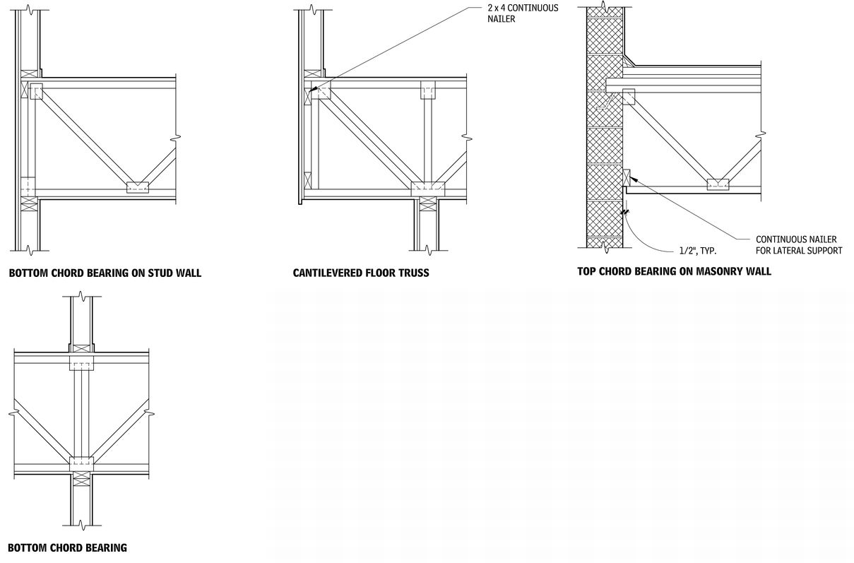
SHOP-FABRICATED WOOD TRUSSES
2.62
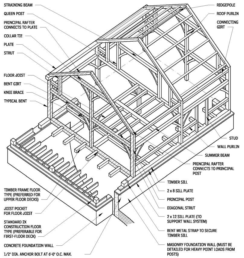
TYPICAL TIMBER FRAME (SHOWING TWO-ROOF AND FLOOR TYPES)
2.63
HEAVY TIMBER CONSTRUCTION
Heavy timber construction is characterized by large, exposed timber columns, beams, and other structural members, joined together by traditional pegged mortise-and-tenon or similar joints. Heavy timber uses rectangular solid-wood framing members that are a nominally a minimum of 5 in., in both dimensions. Heavy timber fabricated timber frame modules are called bents. Bents run perpendicular to the ridge, and include the primary columns, beams, girders, and rafters, and knee braces. Bents are typically spaced 10 to 16 ft on center. Note that alternate framing methods running parallel to the ridge, or utilizing systems similar in concept to platform framing, are available from some timber framers. Knee braces typically provide bracing against lateral loads.
Heavy timber structures are typically enclosed with stressed-skin insulated panels, leaving the frame totally exposed on the interior. Heavy timber construction is being updated with modern materials such as glulam members and proprietary concealed metal connections.
NOTE
2.63 Shaded members represent components of a typical bent.
Contributors:
Tedd Benson and Ben Brungraber, PhD, PE, Benson Woodworking Co., Inc., Alstead, New Hampshire; Timothy B. McDonald, Washington, DC; Richard J. Vitullo, AIA, Oak Leaf Studio, Corwnsville, Maryland.
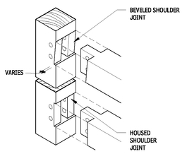
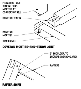
SHOULDERED MORTISE-AND-TENON JOINT
2.64
A beveled shoulder or housed joint is used to connect all load-bearing beams (such as bent and connecting girts and summer beams) to posts. Angled variations can be used when principal rafters join to posts or for diagonal braces. The depth of the shoulder depends on loading, torsion, other joinery in the area, and wood species.
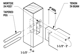
BASIC MORTISE-AND-TENON JOINT
2.65
The basic mortise-and-tenon joint can be very effective in resisting both tension and compression forces. To increase tensile strength, increase the depth and thickness of the tenon and use additional pegs if the width and length of the tenon allow.
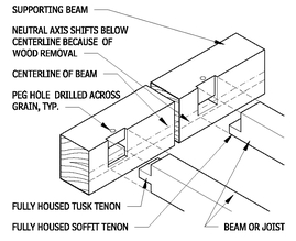
TUSK AND SOFFIT TENON JOINT
2.66
OPEN MORTISE-AND-TENON JOINTS
2.67
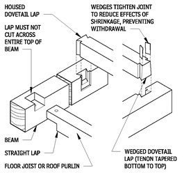
LAP JOINTS
2.68
Contributors:
Tedd Benson and Ben Brungraber, PhD, PE, Benson Woodworking Co., Inc., Alstead, New Hampshire; Richard J. Vitullo, AIA, Oak Leaf Studio, Corwnsville, Maryland.
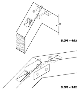
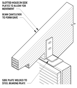
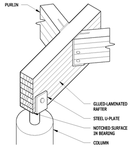
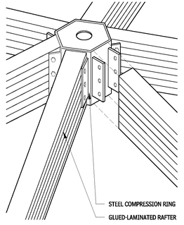
GLUED-LAMINATED CONSTRUCTION
The term glued-laminated construction refers to an engineered, stress-rated product made of wood laminations bonded with adhesives, with the grain approximately parallel lengthwise. Laminated pieces can be end-joined to form any length, be glued edge to edge to make wider pieces, or be of bent pieces curved during the laminating process.
STANDARD DEPTHS
Dimension lumber surfaced to 1-1/2 in. is used to laminate straight members and members that have a curvature within the bending radius limitations for the species. Boards surfaced to 3/4 in. are recommended for laminating curved members when the bending radius is too short to permit the use of dimension lumber, provided that the bending radius limitations for the species are observed. Other lamination thicknesses may be used to meet special requirements.
STANDARD WIDTHS
2.69
| NOMINAL WIDTH (IN.) | NET FINISHED WIDTH (IN.) |
|---|
| 3 | 2-1/8 |
| 4 | 3-1/8a |
| 6 | 5-1/8a |
| 8 | 6-3/4 |
| 10 | 8-3/4a |
| 12 | 10-3/4a |
| 14 | 12-1/4 |
| 16 | 14-1/4 |
CONNECTION DESIGN
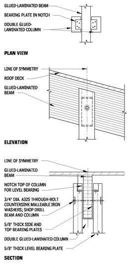
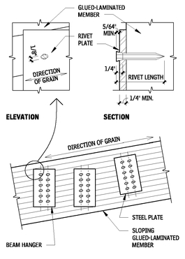
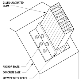
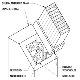
The design of connections for glued-laminated construction is similar to the design of connections for dimension lumber. Since glued-laminated members often are much larger than dimension lumber, and the loads transferred are larger, the effect of increased size should be taken into account in the design of connections. In addition to being designed for strength to transfer loads, connections also should be designed to avoid splitting of the member, as well as to accommodate swelling and shrinking of the wood.
FIRE SAFETY
Similar in nature to those of heavy timber, the self-insulating qualities of glued-laminated construction cause the members to burn slowly. Good structural details, elimination of concealed spaces, and use of vertical fireblocking contribute to its fire resistance and ability to retains its strength longer than unprotected metals.
Therefore, building codes generally classify glued-laminated construction as heavy timber construction if certain minimum dimensional requirements are met. Codes also allow for calculation of one-hour fire ratings for exposed glue-laminated members.
It is not recommended that fire-retardant treatments be applied to glued-laminated members because they do not substantially increase the fire resistance. In considering fire-retardant treatments, it is essential to investigate the following: reduction of strength related to type and penetration of treatment, compatibility of treatment and adhesive, use of special gluing methods, difficulty of application, and effect on wood color and fabrication process.
PROPRIETARY CONNECTIONS
2.70
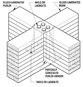
PURLIN-TO-BEAM CONNECTION
2.71
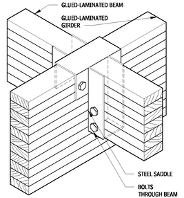
BEAM-TO-GIRDER CONNECTION
2.72
NOTES
2.69 a. Widths are 3, 5, 8-1/2, and 10-1/2 in. for southern pine.
2.70 a. Most typical connections can be accomplished with concealed or semiconcealed fasteners.
b. Final engineering is by manufacturer.
Contributor:
Timothy B. McDonald, Washington, DC.
FLOOR DECKS AND SLABS
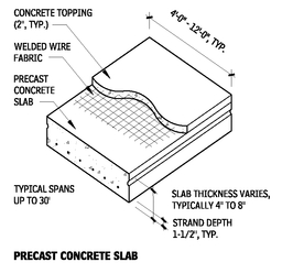
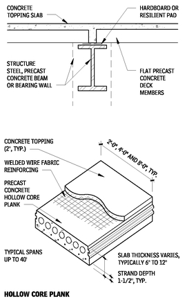
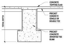
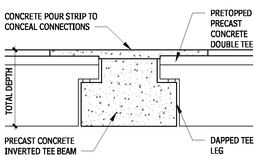
PRECAST CONCRETE DECKS AND SLABS
Normal weight (150 pcf) or lightweight concrete (115 pcf) is used in standard precast concrete slab construction. Concrete topping is usually normal-weight concrete with a cylinder strength of 3000 psi. All units are prestressed with strand release once concrete strength is 3500 psi. Strands are available in various sizes, strengths, and placements, according to individual manufacturers.
Camber varies substantially depending on slab design, span, and loading. Nonstructural components attached to members may be affected by camber variations. Calculations of topping quantities should recognize camber variations. Safe superimposed surface loads include a dead load of 10 psf for untopped concrete and 15 psf for topped concrete. The remainder is live load.
FLAT DECK MEMBERS
2.73
SINGLE OR DOUBLE TEE MEMBERS
2.74
FLAT DECKS
2.75
TEE DECKS
2.76
TEE DECKS DAPPED
2.77
Contributor:
Timothy B. McDonald, Washington, DC.
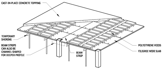
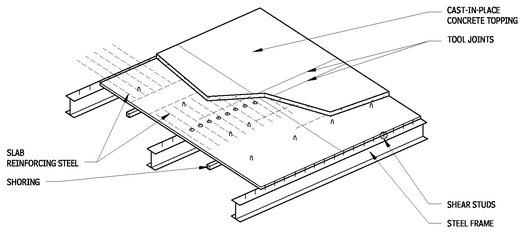
FILIGREE SLABS
Filigree slabs combine desirable characteristics of cast-in-place and precast concrete. The precast filigree panels act as permanent forms for the field-placed reinforcing and cast-in-place (CIP) topping. Slabs can be used with CIP frame, precast frame, or steel frame or with bearing wall construction. The underside of the filigree panels is smooth enough to remain exposed.
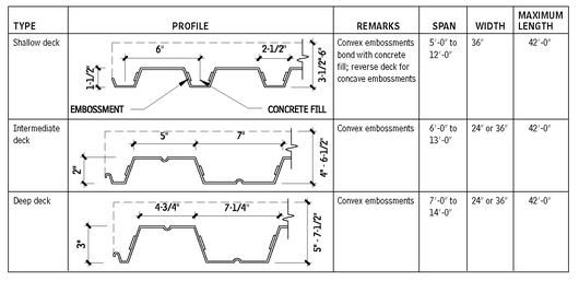
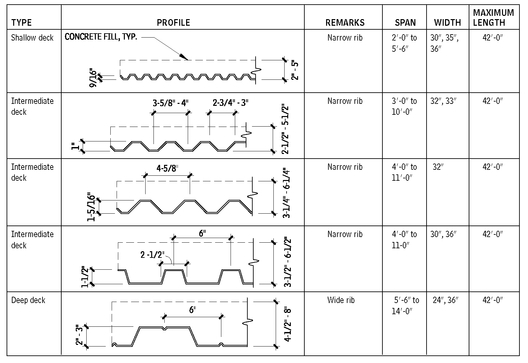
METAL FLOOR DECKING
When designing with metal decking, two guidelines are important to follow:
• When lightweight concrete is used in the construction, use galvanized deck material.
• In a fire-resistant assembly, ensure that metal components are unprimed.
These are some advantages of metal floor decks:
• They provide a working platform, eliminating temporary wood planking in high-rise use.
• Composite decks provide positive reinforcement for concrete slabs.
• Both noncomposite and composite decks serve as forms for concrete, eliminating the need for forming and stripping.
• Acoustical treatment is possible.
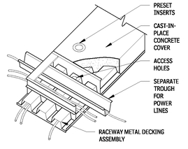
• Electric raceways may be built into the floor slab.
• Metal floor decking provides economical floor assemblies.
Consult independent testing laboratory directories for specific firerating requirements.
FILIGREE FLAT PLATE
2.78
FILIGREE ON STEEL
2.79
COMPOSITE FLOOR DECK WITH CONCRETE FILL
2.80
NOTE
2.78 Required field placed reinforcing steel not shown for clarity.
Contributors:
Midstate Filigree Systems,
www.filigreein.com; Donald J. Neubauer, PE, Neubauer-Sohn, Consulting Engineers, Potomac, Maryland; Walter D. Shapiro, PE, Tor, Shapiro & Associates, New York City, New York.
NONCOMPOSITE FLOOR DECK WITH CONCRETE FILL
2.81
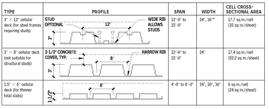
COMPOSITE AND NONCOMPOSITE CELLULAR FLOOR DECK WITH CONCRETE FILL
2.82
ELECTRICAL TRENCH DUCT
2.83
FLOOR DECK ACCESSORIES
2.84
WOOD DECKING
POST AND BEAM CONNECTIONS
2.85
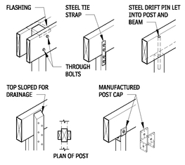
NOTES
2.83 a. Electric raceways may be built into floor slabs by using cellular deck or special units that are blended with plain deck. Two-way distribution is achieved by using trench ducts that sit astride the cellular units at right angles.
b. Using trench ducts with composite floor deck may reduce or eliminate entirely the effectiveness of composite action at the trench duct. This is also true for composite action between steel floor beams and concrete fill. Trench duct locations must be taken into account in deciding whether composite action is possible.
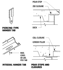
2.84 A convenient, economical means of supporting lightweight acoustical ceilings is to attach a suspension system to hanger tabs at side laps, pierce tabs driven through the deck, or prepunch tabs in the roof deck. Do not use this tab-and-metal deck arrangement to support plaster ceilings, piping, ductwork, electrical equipment, or other heavy loads. Such elements must be suspended directly from structural members or supplementary subframing.
Contributors:
Donald Neubauer, PE, Neubauer Consulting Engineers, Potomac, Maryland; Walter D. Shapiro, PE, Tor, Shapiro & Associates, New York City, New York; The Bumgardner Architects, Seattle, Washington.
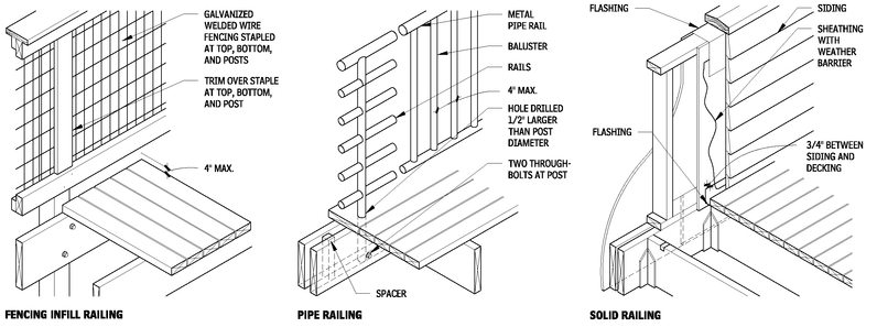
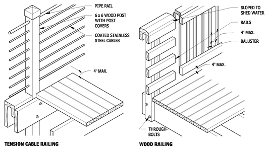
RAILINGS
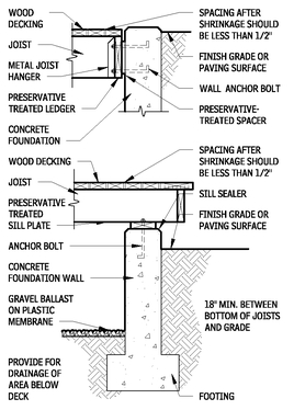
2.86
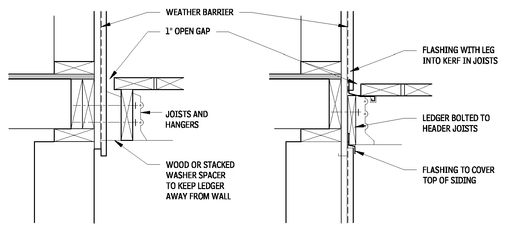
CONNECTIONS AT BUILDING
2.87
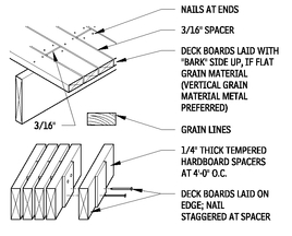
DECKING APPLICATIONS
2.88
WOOD SELECTION
When it comes to selecting wood for decking, characteristics should include effective resistance to decay, nonsplintering, stiffness, strength, hardness, and warp resistance. Species selection will vary according to local climate and structure.
NOTE
2.88 Spacing of 1/4 in. is not recommended for walking surfaces where high heels are anticipated.
Contributor:
The Bumgardner Architects, Seattle, Washington.
RELATIVE COMPARISON OF VARIOUS QUALITIES OF WOOD USED IN DECK CONSTRUCTION
2.89
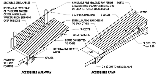
WALKWAYS AND RAMPS
2.90
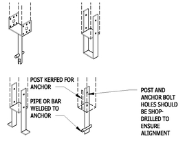
POST BASES
2.91
DECK EDGES
2.92
STEPS AND STAIRS
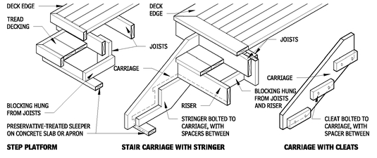
2.93
NOTES
2.89 a. Includes West Coast and eastern hemlocks.
b. Includes western and northeastern pines.
c. Categories refer to semitransparent oil-base stain.
d. Use pressure-preservative-treated material only. All materials below deck surfaces should be pressure-treated.
e. Ipe used typically for decking only, not framing.
Contributors:
The Bumgardner Architects, Seattle, Washington; Mark J. Mazz, AIA, CEA, Inc., Hyattsville, Maryland.
POSTS AND FOOTINGS
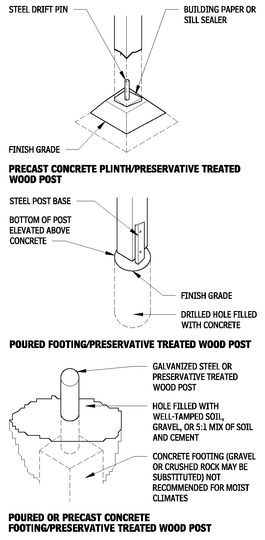
2.94
FASTENERS
Guidelines for selecting fasteners include:
• Use hot-dipped galvanized fasteners to avoid corrosion and staining.
• Preservative treated wood requires stainless steel fasteners or special heavy galvanized coating recommended by the treatment manufacturer.
• To reduce board splitting by nailing, do the following: blunt nail points, predrill (3/4 of nail diameter), stagger nailing, and place nails no closer to the edge than one-half of board thickness.
• Avoid end-grain nailing and toenailing, if possible.
• Use flat washers under heads of lag screws and bolts, and under nuts.
In addition, note that hot-dipped galvanized casing nails or stainless steel deck screws are typically the best type of decking fasteners, and plated ring shank or spiral groove shank nails are suitable for arid climates.
PRESERVATIVE WOOD TREATMENT
To protect wood decking from moisture, follow these guidelines:
• Protect wood members from weather by preservative wood treatment.
• Treat wood in direct contact with soil or concrete with preservative.
• Ensure that the bottoms of posts on piers are 6 in. above grade.
• Sterilize or cover soil with membrane to keep plant growth away from wood members, to minimize moisture exchange.
• Treat ends, cuts, and holes, with preservative before placement.
• Kerf decking and flat-trim boards, 2 by 6 and wider, on the underside with 3/4-in.-deep saw cuts at 1 in. o.c., to prevent cupping.
• Avoid horizontal exposure of end grain, or provide adequate protection by flashing or sealing. Avoid or minimize joint conditions where moisture may be trapped by using spacers and/or flashing, caulking, sealant, or plastic roofing cement.
BRACING
On large decks or decks where post heights exceed 5 ft, lateral stability should be achieved with horizontal bracing (metal or wood diagonal ties on top or bottom of joists or diagonal application of decking), in combination with vertical bracing (rigid bolted or gusseted connections at tops of posts, knee bracing, or cross bracing between posts), and/or connection to a braced building wall. Lateral stability should be assessed by a structural engineer.
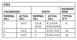
MACHINE-SHAPED DECKING TYPES
2.95
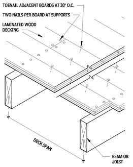
LAMINATED DECKING
2.96
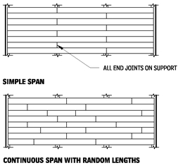
WOOD DECKING JOINT PATTERNS
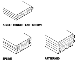
2.97
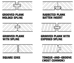
DECKING JOINTS
2.98
Contributors:
The Bumgardner Architects, Seattle, Washington; Mark J. Mazz, AIA, CEA, Inc., Hyattsville, Maryland; David S. Collins, FAIA, American Forest and Paper Association, Cincinnati, Ohio; Timothy B. McDonald, Washington, DC.
FLOOR CONSTRUCTION VAPOR RETARDERS, AIR BARRIERS, AND INSULATION
CRAWL SPACE INSULATION AND VENTILATION
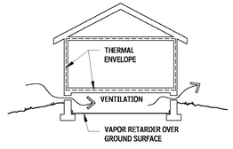
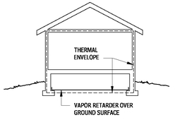
The best understanding of the interrelated issues surrounding control of heat, air, and moisture (HAM) inside crawl spaces and the transfer of HAM to the building interior suggests that it is preferable to treat the crawl space as part of the interior conditioned environment.
Arguments against ventilating crawl spaces include:
• Venting of a crawl space is meant to keep moisture within acceptable levels, pulling hot, humid air into the space is counterproductive, especially when it is likely that the ground surface temperatures may be below the dew point temperature.
• Insulated floor assemblies are rarely constructed airtight and, allow air infiltration/exfiltration.
• Insulated floor assemblies are rarely as warm or as comfortable as floors with a conditioned environment on both sides.
• Conditioned spaces above hot, humid, ventilated crawl spaces create a vapor drive, which may result in excess load on the HVAC, uncontrolled condensation, and potentially rot and mold.
• Crawl spaces are frequently used for distribution of mechanical ductwork. The distribution ductwork is outside of the thermal envelope and, therefore, experiences greater loss than if interior to the thermal envelope. The penetrations required for the ductwork create more opportunities for air leakage between the conditioned and unconditioned space. In hot, humid conditions, there is a likelihood that the vapor retarder on the duct insulation will not be perfect, causing condensation on the ductwork to occur, thereby adding more moisture to an already damp environment.
• Sanitary sewer and domestic water supply lines likely pass through the unconditioned crawl space and may be susceptible to freezing and condensation.
Recommendations for crawl spaces include the following:
• Codes generally require ventilation of crawl spaces; however, they also provide exemptions for a variety of conditions, specifically: “where warranted by climatic conditions,” “where continuously operated mechanical ventilation is provided,” and “when the perimeter walls are insulated.” Most exemptions require the ground surface to be covered with a vapor retarder. Refer to the specific building codes in effect for all requirements.
• Cover the ground surface in the crawl space with a vapor retarder. Tape seams and seal penetrations. Consider protecting the vapor retarder with a rough concrete mud slab. Mechanically fasten the retarder to the foundation at the perimeter with a nailing strip. In cold climates, it may be desirable to insulate the entire ground surface.
• Insulate the crawl space walls as required by code. Follow recommendations for exterior walls regarding the permeability of insulation materials, air sealing, and the use of vapor retarders. Insulation may need to be fire-rated, especially board insulation; or use noncombustible-type insulation. If possible, locate insulation outside of the dampproofing on the foundation wall.
• Ventilate the crawl space, typically with a small supply duct at code-specified rate, normally 1 cfm for each 50 sq ft, and provide connection to the return air plenum, either directly or through the interior space above via transfer grilles. Locate the supply and return points to evenly mix and distribute the air.
• Alternative crawl space drying methods include a permanent dehumidifier or exhaust fans controlled by humidistats, with makeup air from the interior and ducted to the exterior. However, this solution may use a large amount of energy.
• Pay attention to exterior wall detailing and proper drainage to keep water away from the crawl space.
• Crawl spaces used as the supply plenum to the remainder of the house require special treatment to maintain air quality.
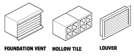
CRAWL SPACE VENTILATION MATERIALS
2.99
VENTILATED CRAWL SPACE
2.100
CONDITIONED CRAWL SPACE
2.101
WOOD FRAME OVER CRAWL SPACE (COLD CLIMATE)
2.102
Contributors:
Joe Lstriburek, Building Sciences Corporation, Richard J. Vitullo, AIA, Oak Leaf Studio, Crownsville, Maryland; Eric Gastier, Alexandria, Virginia.
WOOD FRAME OVER CRAWL SPACE (MIXED CLIMATE)
2.103
INSULATING UNDERSIDE OF STEEL AND CONCRETE FLOOR STRUCTURES
2.104
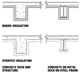
Two primary difficulties encountered with the insulation of floor assemblies are providing a continuous vapor retarder on the warm side, and keeping the floor warm, even with insulation. In cold climates, the floor will be uncomfortable for any long-term occupancy. If possible, it is best to avoid insulation applied directly to the bottom of floor assemblies; instead, use an insulated soffit. If direct application is unavoidable, consider the following two following methods:
• Board insulation is typically applied to the underside of the structure by impaling over adhesive-applied stickpins and crimped with large washers. Mineral wool insulation is a good choice because it is noncombustible and performs well even if it becomes slightly damp from condensation.
• Sprayed insulation can be cellulose-based, mineral-based, or foam. Closed-cell foam can eliminate the need for a separate vapor barrier.
ROOF CONSTRUCTION
This section examines common systems used in roof construction. Consult literature from manufacturers and trade associations for more details on the information presented in the accompanying tables.
Contributors:
Joe Lstriburek, Building Sciences Corporation, Richard J. Vitullo, AIA, Oak Leaf Studio, Crownsville, Maryland; Eric Gastier, Alexandria, Virginia.
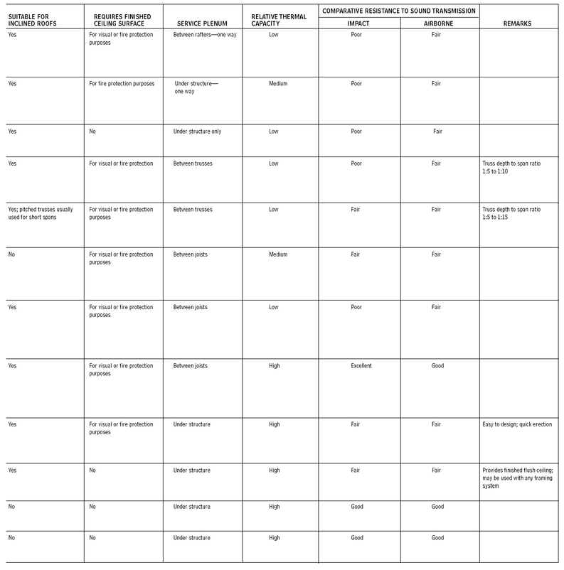
ROOF STRUCTURE ASSEMBLIES
2.105
Contributors:
Roger K. Lewis, FAIA, and Mehmet T. Ergene, architect, Roger K. Lewis and Associates, Washington, DC.
Contributors:
Roger K. Lewis, FAIA, and Mehmet T. Ergene, architect, Roger K. Lewis and Associates, Washington, DC.
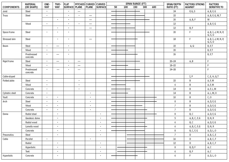
LONG-SPAN AND TENSILE STRUCTURES
DESIGN CONSIDERATION FACTORS
Examples of long-span structures shown in Table 2.126 are rated for their capability to address the following design factor conditions.
NATURAL CONDITIONS
A. Uneven or excessive snow and ice loads: Geometry, equipment, or surrounding structure may contribute to snow drifting or ice buildup.
B. Ponding: Provide positive drainage to remove water from the structure when roof drains clog.
C. Wind: Evaluate potential of wind-induced destructive vibration in members or connections.
D. Thermal: Daily and seasonal temperature cycles can cause significant changes in structural shape and member stresses, and may lead to fatigue failure.
E. Freeze/thaw cycles or corrosive atmosphere: Evaluate long-term effects on structural performance, particularly for exposed concrete structures.
PRIMARY STRESSES
F. Load paths: Two or more load paths for all loads should be provided wherever possible. The greater the area a single member supports, the greater should be its safety factor.
G. Compression failure: Resistance to lateral buckling of long members is crucial. Use members that ensure initial and verifiable alignment.
H. Tension failure: Dynamic stability under wind or other vibration loading should be carefully verified.
SECONDARY STRESSES
I. Deflection: Changes in orientation of members at joints can increase distructive stresses from loads.
J. Member interaction: Load flows through structures in such a way as to minimize strength. Check all possible load paths of complex geometric structures.
K. Nonstructural connections: Assemblies attached to a structure will influence structural load flow and even become part of the load flow if the attachment changes the deflected shape.
L. Scale: Most members have a span limit, beyond which weight of the member itself becomes a limiting factor.
M. Stress concentration: Check stresses at changes of cross sections, holes, and connections. High-strength materials are particularly sensitive.
TOLERANCES
N. Erection alignment: True member length and spatial position are crucial for proper alignment and load flow.
O. Creep: Length changes over time will influence both primary and secondary stresses.
P. Supports and foundations: Supports must accept movements due to deflections from primary and secondary stresses and differential foundation settlement.
QUALITY CONTROL
Q. Design: Engineering design must not be compromised by time, scheduling, design changes, or building codes.
R. Methods: Construction methods should be selected carefully to safely and accurately locate the structural components.
S. Site observation: Only when the structure is properly established in space should it be accepted. Changes in construction materials or methods should be carefully evaluated.
T. Structural building maintenance: Conditions and alignment of various members, especially crucial nonredundant members, should be verified on a regular schedule. Consider using equipment to detect excessive deflection.
U. Nonstructural building maintenance: The condition of building components should not adversely affect the structure (e.g., keep roof drains open, prevent excessive equipment vibration, and maintain expansion joints).
LONG-SPAN COMPONENTS
2.106
NOTES
2.106 a. Steel is A-36; wood is laminated, sometimes heavy timber; concrete is reinforced with steel; prestressed concrete is prestressed with steel.
b. Cable-stayed system can give auxiliary support to trusses, beams, or frames, greatly reducing span and member sizes, but providing additional tensional strength.
c. Lamella arches provide two-way arch structures and improve redundancy.
d. Domes may also be constructed of aluminum.
e. Pneumatics are fabric roofs, pressurized, and stabilized with steel cables.
f. For each system, the following notation applies: the bullet (•) indicates the typical configuration; the dash (—) indicates occasionally used.
Contributor:
William C. Bauman, Jr., University of Oklahoma, Norman, Oklahoma.
SPACE FRAMES
A space frame is a three-dimensional truss with linear members that form a series of triangulated polyhedrons. It can be seen as a plane of constant depth that can sustain fairly long spans and varied configurations of shape.
Space frames prime attributes include:
• Light weight
• Inherent rigidity
• Wide variety of form, size, and span
• Compatible interaction with services, primarily HVAC
Most space frames are designed for specific applications, and a structural engineer with specific experience should be consulted. Manufacturers can provide the full range of capabilities (loading, spans, shapes, specific details) for their products. Standardized structural assemblies in 4- and 5-ft modules are available.
Metal space frames are classified as noncombustible construction, and can usually be exposed when 20 ft above the floor. However, a fire suppression or a rated ceiling assembly may be required. Consult codes.
Common finishes include paint, thermoset polyester, galvanized, stainless steel, and metal plating.
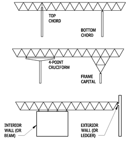
SUPPORT TYPES
2.107
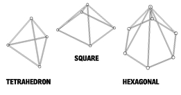
COMMON PATTERNS
2.108
MODULE SELECTION AND CHARACTERISTICS
2.109
Select a space frame module that is compatible with the structural module in shape (e.g., a square module with orthogonal plan) and size (a multiple of the structural module), is consistent with the limitations of the interfacing systems (e.g., the maximum span of the roof deck or mullion spacing of the glazing system), and satisfies the spatial and aesthetic effects in scale and form.
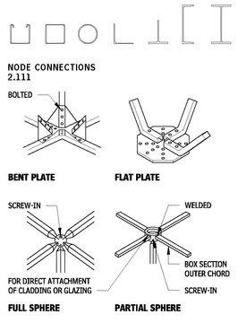
MEMBER SHAPES
2.110
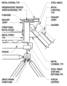
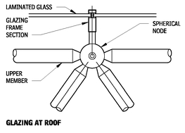
SLOPED GLAZING
2.112
NOTES
2.108 Many proprietary node systems are available for specific applications and budgets. Keep field connections to a minimum; welded connections often eliminate joint pieces.
2.110 Square tubes or angles within their span range are often the most economical.
2.111 Space frame supports are at joints only, not along members.
Contributor:
Severud Associates, New York City, New York.
GRID SHAPES
2.113
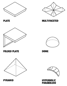
SPACE FRAME FORM TYPES
2.114
ROOF AND FLOOR CONNECTIONS
2.115
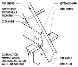
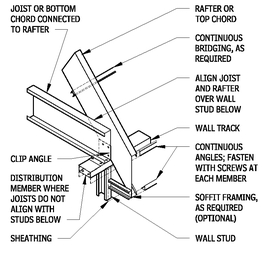
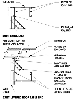
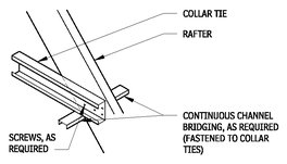
COLD-FORMED METAL ROOF FRAMING
Cold-formed steel (CFS) framing members can be used to frame roofs in essentially the same manner as wood rafters or trusses. Note that thermal bridging can be a problem in cold climates when CFS members are not covered by continuous insulation.
Similarly cold-formed metal floor joist framing, including the use of delegated design, the following considerations should be considered when utilizing CFS for roof framing:
• Cold-formed metal roof framing uses C-shaped members, in sizes approximating wood framing, with special details for sloped bearing conditions.
• CFS framing is laid out similar to traditional wood joist framing.
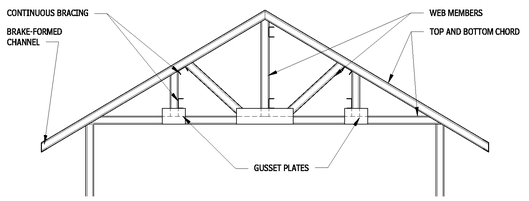
• CFS roof trusses are available in virtually all of the configurations available for wood trusses.
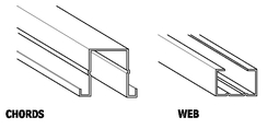
• Proprietary roof truss systems use various shapes for chords and webs designed to allow higher productivity in fabrication and optimization of structural performance. It is generally not advisable to design around any single system, but instead to provide a general shape that many fabricators can provide.
For more information, consult the reference “Product Technical Information,” Steel Stud Manufacturers Association,
www.ssma.com.
COLD-FORMED METAL ROOF FRAMING DETAILS
COLD-FORMED STEEL ROOF TRUSSES
2.116
WEB MEMBERS
2.117
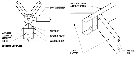
RIDGE BOARD
2.118
NOTES
2.116 a. Chords and webs can be typical CFS C-shapes or a variety of proprietary special shapes.
b. Bracing is typically channel or track.
c. Gusset plates from flat plate or section of large C-shape.
Contributors:
American Iron and Steel Institute, Washington, DC; Severud Associates, New York City, New York.
ROOF EAVE AT CATHEDRAL CEILING
2.119
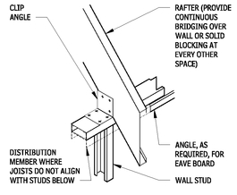
ROOF TRUSS EAVE DETAIL
2.120
ROOF EAVE DETAIL
2.121
ROOF END DETAILS
2.122
COLLAR TIE DETAIL
2.123
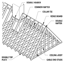
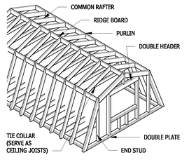
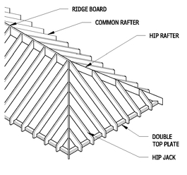
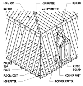
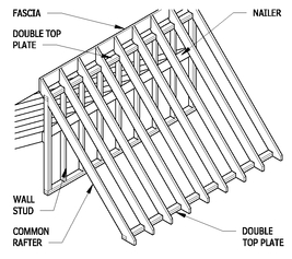
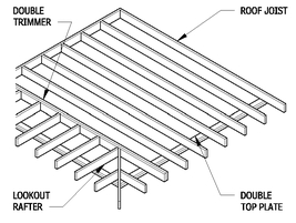
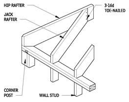
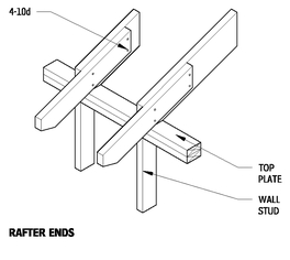
FRAMING DETAILS FOR WOODROOFS
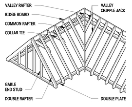
These figures illustrate details of common types of roof framing.
GABLE ROOF
2.124
GAMBREL ROOF
2.125
HIP ROOF
2.126
NOTE
2.122 Provide bridging at ceiling joists and roof rafters, and continuous bridging between rafters at the wall.
Contributors:
American Iron and Steel Institute, Washington, DC.; Timothy B. McDonald, Washington, DC.
MANSARD ROOF
2.127
SHED ROOF
2.128
FLAT ROOF
2.129
JACK RAFTERS
2.130
ROOF PEAK
2.131
RAFTER TAILS
2.132
INTERSECTING ROOF
2.133
RAFTERS AND CEILING JOISTS RESTING ON WALL PLATES
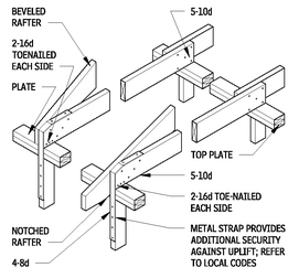
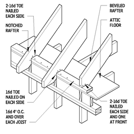
2.134
NOTCHED OR BEVELED RAFTERS RESTING ON PLATE
2.135
Contributors:
Timothy B. McDonald, Washington, DC.; Joseph A. Wilkes, FAIA, Wilkes and Associates, Washington, DC.
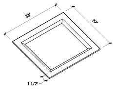
CURB FOR SKYLIGHT
2.136
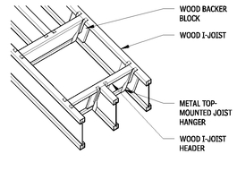
WOOD I-JOIST CONSTRUCTION DETAILS
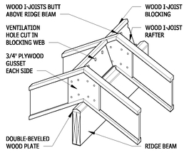
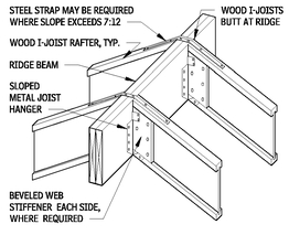
WOOD I-JOIST RAFTER AT RIDGE BEAM DETAIL
2.137
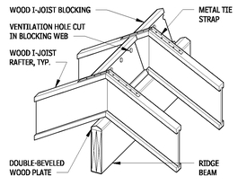
WOOD I-JOIST RAFTER AT RIDGE BEAM DETAIL
2.138
WOOD I-JOIST RAFTER AT RIDGE BEAM DETAIL
2.139
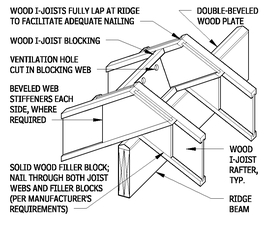
LAPPED WOOD I-JOIST RAFTER AT RIDGE BEAM
2.140
WOOD I-JOIST RAFTER AT OVERHANG
2.141
WOOD I-JOIST RAFTER AT OVERHANG
2.142
WOOD I-JOIST RAFTER AT OVERHANG
2.143
TYPICAL BIRD’S MOUTH I-JOIST CUT DETAIL
2.144
NOTES
2.137 Uplift connections may be required.
2.138 Uplift connections may be required.
2.139 Uplift connections may be required.
2.140 Uplift connections may be required.
2.141 Uplift connections may be required.
2.142 Uplift connections may be required.
2.143 a. Uplift connections may be required.
b. Special sloped seat-bearing metal connectors can be used in lieu of beveled wood plate in some sloped applications. See manufacturer’s recommendations.
2.144 Uplift connections may be required.
Contributor:
Richard J., Vitullo, AIA, Oak Leaf Studio, Crownsville, Maryland.
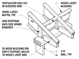
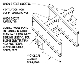
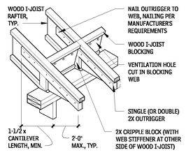
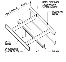
WOOD I-JOIST RAFTER WITH OUTRIGGER
2.145
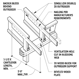
WOOD I-JOIST RAFTER AT OUTRIGGER
2.146
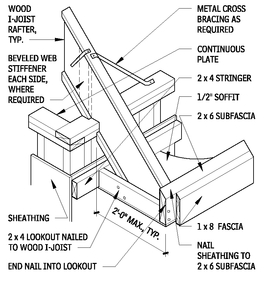
FLY RAFTER DETAIL
2.147
WOOD I-JOIST SKYLIGHT FRAMING DETAIL
2.148
SHOP-FABRICATED WOOD TRUSSES
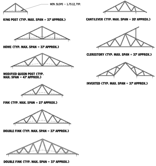
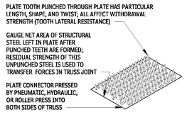
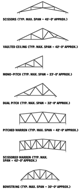
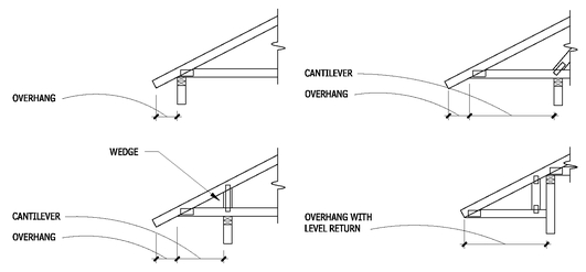
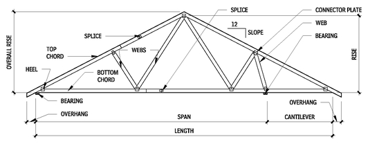
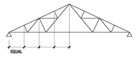
Shop-fabricated wood trusses have been used in building construction since 1953, when the metal connector plate was invented. Metal plates are available in a range of styles and tooth orientations. The metal plates are punched with barbs that grab onto the wood truss, thus reducing the hand-nailing required to fabricate a structure. Plate size for a given truss is based on a combination of the tooth withdrawal strength of the plate, the tensile and shear strength of the steel, and the net sectional area of the lumber.
PITCHED CHORD TRUSSES
2.149
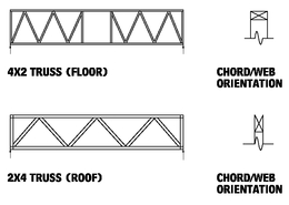
This system is primarily used for roofs with either pitched or parallel chord trusses. It is occasionally employed for floors with parallel chord trusses. Individual trusses are cut from 2-by-4-in. or 2-by-6-in. dimension lumber and can be spaced 24 in. or 48 in. o.c. For typical residential construction, 24 in. o.c. is used. Exceptionally long spans are possible with shop-fabricated wood trusses, allowing the large, unencumbered interior spaces often required in commercial, agricultural, and other nonresidential building types.
Camber is designed for dead load only: Camber (in.) = Length (ft)/60
BRACING
Providing adequate bracing for trusses is essential, both during installation and as a component of the overall roof design. Truss members must be held in place with supports that meet them at right angles. Truss chords and web members are placed in a vertical, plumb position, and maintain that position, resisting applied design loads throughout the life of the structure. Permanent bracing and anchorage are expected to be an integral part of construction, and strongbacks are often used for this purpose.
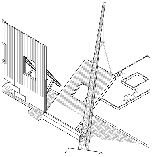
Movement by crane can damage trusses. Crane spreader bars are used to avoid this “out-of-plane” buckling. Special stiffening may be applied to trusses during erection.
NOTES
2.146 Uplift connections may be required.
2.148 Check code and manufacturer’s requirements for all ventilation hole sizes cut in blocking web.
2.149 a. The average spacing for light trusses (trussed rafters) is 2 ft o.c., but it varies, up to 4 ft. The average combined dead and live loads is 45 lb per sq ft. Spans are usually between 20 and 32 ft, but can be as much as 50 ft.
b. Early in the design process, consult an engineer or truss supplier for preengineered truss designs to establish the most economical and efficient truss proportions. The supplier may provide final truss engineering design.
c. Permanent and temporary erection bracing must be installed as specified to prevent failure of properly designed trusses.
d. Some locales require an engineer’s stamp when prefab trusses are used. Check local codes.
e. Member forces in a truss rise rapidly as the lower chord is raised above the horizontal.
Contributor:
Richard J. Vitullo, AIA, Oak Leaf Studio, Crownsville, Maryland.
TYPICAL METAL PLATE CONNECTOR
2.150
PITCHED TRUSSES
2.151
PARALLEL TRUSSES
2.152
SPLIT-RING WOOD TRUSSES
The first wood trusses were developed for bridge design, with the kingpost truss being the earliest form. It uses a primary engineering principle: a triangle will hold its shape under a load until its side members or its joints are crushed. Next came the queenpost truss, in which the peak of the kingpost was replaced by a horizontal crosspiece to allow a longer base.
Further amplifications permitted greater flexibility, to overcome different spanning challenges and to integrate various combinations of inclined wood braces, wood arches, steel tension rods, and other structural members.
When working with these trusses, keep the following in mind:
• A built-in camber of approximately 1 in. per 40-ft span will be introduced in the top and bottom chords during fabrication.
• When lumber is not adequately seasoned, the trusses should be inspected periodically, and adjusted, if necessary, until moisture equilibrium is reached.
Contributors:
Richard J. Vitullo, AIA, Oak Leaf Studio, Crownsville, Maryland; TECO Products, Collier, West Virginia.
OVERHANG DETAILS
2.153
TYPICAL PITCHED CHORD ROOF TRUSS
2.154
QUEENPOST AND KINGPOST
2.155
• Pitched trusses are very economical for spans up to 70 ft (with an average spacing of 15 ft), for three reasons: the member sizes are small, the joint details are relatively simple, and the trusses are easily fabricated. All pitched trusses require either knee braces to columns or some other provision for lateral restraint against wind or other forces.
• A typical span (l) to depth (d) ratio for the Pratt, Howe, or Belgian truss is 4 to 6, which gives a relatively normal slope of 4:12 to 6:12. Fink trusses are preferred where the slope is steep (over 7:12). Scissors trusses and other types of raised lower-chord pitched roof trusses are used for special conditions where clearance or appearance requires an arched bottom chord.
PITCHED TRUSSES
2.156
CONNECTORS
2.157
SPLIT-RING CONNECTOR
2.158
GLUED-LAMINATED CONSTRUCTION
STRUCTURAL GLUED-LAMINATED SHAPES
2.159
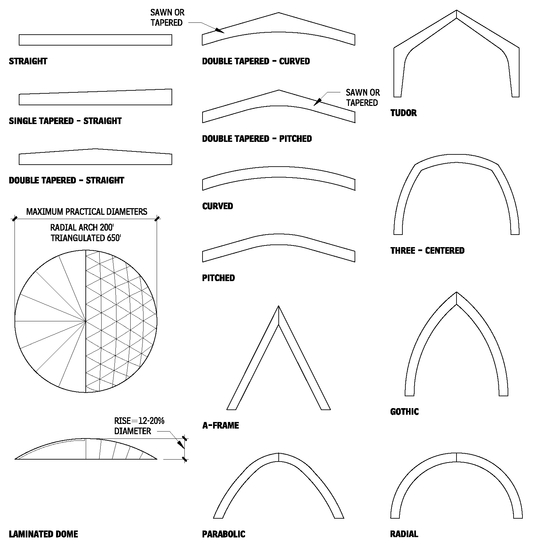
When examining the shapes of structural glued-laminated members, note the following:
• Beam names describe top and bottom surfaces of the beam. Sloped or pitched surfaces should be used on the tension side of the beam.
• The three-hinged arches and frames shown in Figure 2.175 produce horizontal reactions requiring horizontal ties or modified foundations.
• The triangulated and the radial arch are the two basic types of structural glued-laminated wood dome systems available. Both require a tension ring at the dome spring line to convert axial thrusts to vertical loads. Consideration must be given to the perimeter bond beam design, as wind forces will produce loads in this member. The lengths of the main members of the radial arch system, which must span a distance greater than half the dome diameter, limit the maximum practical dome diameter. The much smaller members of the triangulated dome result in the greater diameters. The triangulated system can be designed for five or more segments, with an equal number of peripheral supports at each segment.
• More complicated shapes may be fabricated. Contact the American Institute of Timber Construction (AITC) and APA - Engineered Wood Association.
NOTE
2.157 Shear plate connectors are commonly used to connect wood truss members to steel gusset plates, but they may be used to connect wood to wood, as well.
Contributors:
TECO Products, Collier, West Virginia; Richard J. Vitullo, AIA, Oak Leaf Studio, Crownsville, Maryland; Roger W. Kipp, AIA, Thomas Hodne Architects, Inc., Minneapolis, Minnesota.
GLUED-LAMINATED COLUMN WITH ROOF BEAM
2.160
GLUED-LAMINATED BEAM/CONCEALED DOUBLE COLUMN
2.161
GLUED-LAMINATED RIVET CONNECTION AND INSTALLATION DETAILS
2.162
GLUED-LAMINATED CONSTRUCTION: CONNECTIONS
FIXED-ARCH ANCHORAGE
2.163
TRUE HINGE ANCHORAGE FOR ARCHES
2.164
NOTES
2.162 a. Rivets must be installed with their long axis parallel to the grain of the wood.
b. Rivets must be driven so that the conical head is firmly seated in the hole, but not flush.
c. Side plates must be at least 1/4-in. thick and must be hot dipped galvanized for use in wet service conditions.
d. Steel plates must be drilled (not punched) with 17/64- to 9/32-in. holes to accommodate the rivets.
Contributors:
David Nairne-Associates Ltds., North Vancouver, British Columbia; Timothy B. McDonald, Washington, DC.
ARCH PEAK CONNECTION
2.165
RAFTER TO COLUMN CONDITION
2.166
RAFTER TO BEARING WALL
2.167
NOTCHED BEARING CONDITION
2.168
STEEL COMPRESSION BOX
2.169
SPECIAL CONNECTION
2.170
GLUED-LAMINATED COLUMNS
2.171
NOTES
2.168 a. An abrupt notch in the end of a wood member reduces the effective shear strength of the member and may permit a more rapid migration of moisture in the lower portion of the member, potentially causing splitting.
b. The shear strength of the end of the member is reduced, and the exposed end grain may also result in splitting because of drying. At inclined beams, the taper cut should be loaded in bearing.
2.170 One of a large variety of special connections and connection assemblies that are possible using structural glued-laminated timber. It is critical that connections be designed carefully in accordance with good engineering practice.
Contributors:
Roger W. Kipp, AIA, Thomas Hodne Architects, Inc., Minneapolis, Minnesota; Timothy B. McDonald, Washington, DC.
ROOF DECKING
This section examines common types of roof decking, including metal decking, grouted roof decking, and timber frame roof decking.
METAL ROOF DECKING
Some of the many types of available metal roof decking include:
• Roof decking
• Composite deck
• Permanent forms for self-supporting concrete slabs
• Raceway (composite or noncomposite)
• Acoustical metal decking
• Acoustical cellular deck (composite or noncomposite)
• Vented roof deck (used with lightweight insulating concrete fill)
INSTALLATION AND DESIGN
Metal roof decks must be secured to supports, generally by means of welds made through the decking to supporting steel. Steel sheet lighter than 22 gauge should be secured by use of welding washers.
Side laps between adjacent sheets of deck must be secured by button-punching standing seams, welding, or screws, in accordance with the manufacturer’s recommendations.
Decks used as lateral diaphragms must be welded to steel supports around their entire perimeter to ensure development of diaphragm action. More stringent requirements may govern the size and/or spacing of attachments to supports and side lap fasteners or welds.
Roof deck selection must consider construction and maintenance loads, as well as the capacity to support uniformly distributed live loads. Consult the Steel Deck Institute’s recommendations and Factory Mutual Global’s requirements.
Heavy roof-mounted mechanical equipment should not be placed directly on a metal roof deck. Equipment on curbs should be supported directly on main and supplementary structural members, and the deck must be supported along all free edges. Heavy items such as cooling towers that must be elevated should be supported directly onto structural members below the deck.
FIRE-RESISTANCE RATINGS
Fire-resistance ratings for roof assemblies are published by Code authorities, Underwriters Laboratories and Factory Mutual. Fire-Resistance ratings may be achieved by various methods including applied fireproofing, rated acoustical ceilings, and gypsum board enclosures.
ADVANTAGES OF METAL ROOF DECKS
There are a number of advantages to using metal roof decks:
• A high strength-to-weight ratio reduces roof dead load.
• They can be erected in most weather conditions.
• A variety of depths and rib patterns are available.
ROOF DECK ACCESSORIES
2.172
• Acoustical treatment is possible.
• They can serve as the base for insulation and roofing.
• Fire ratings can be obtained with standard assemblies.
• They can provide a lateral diaphragm.
• They can be erected quickly and economically.
• Using them makes it easy and economical to create roof slopes for drainage when mounted over sloped structural steel.
OPENINGS IN DECK
2.173
RECESSED SUMP PAN
2.174
METAL ROOF DECK TYPES
2.175
NOTES
2.173 a. Small openings (up to 6 by 6 in. or 6 in. in diameter) usually may be cut in a roof or floor deck without reinforcing the deck.
b. Openings up to 10 by 10 in. or 10 in. in diameter require reinforcing of the deck either by welding a reinforcing plate to the deck all around the openings or providing channel-shaped headers and/or supplementary reinforcing parallel to the deck span. Reinforcing plates should be 14-gauge sheets with a minimum projection of 6 in. beyond all sides of the opening, and they should be welded to each cell of the deck.
c. Larger openings should be framed with supplementary steel members so that all free edges of the deck are supported.
2.174 Preformed recessed sump pans are available from deck manufacturers for use at roof drains.
Contributors:
Donald Neubauer, PE, Neubauer Consulting Engineers, Potomac, Maryland; Walter D. Shapiro, PE, Tor, Shapiro & Associates, New York City, New York.
TIMBER FRAME ROOF DECKING
WOOD SLEEPERS AND TONGUE-AND-GROOVE CEILING ON ROOF PURLINS
2.176
WOOD NAILERS ON ROOF PURLINS
2.177
ROOF SHEATHING AND PANELS
OPEN SOFFIT
2.178
CLOSED SOFFIT
2.179
GABLE ROOF
2.180
FLAT LOW-PITCHED ROOF
2.181
CONNECTIONS TO STEEL JOIST
2.182
CAST ROOF DECKS
2.183
NOTE
2.178 Any appropriate exterior or exposure panel grade of adequate span rating to carry design roof loads, refer to Chapter 11.
Contributors:
APA-Engineered Wood Association, Tacoma, Washington; BSB Design, Des Moines, Iowa; Richard J. Vitullo, AIA, Oak Leaf Studio, Crownsville, Maryland; Tedd Benson and Ben Brungraber, PhD, PE, Benson Woodworking Co., Inc., Alstead, New Hampshire.
STRUCTURAL INSULATED PANELS (SIP)
2.184
ROOF FRAMING WITH RAFTERS AND TRUSSES
2.185
ROOF FRAMING WITH RIDGE BEAM
2.186
ROOF EAVE DETAIL WITH SLOPED CEILING
2.187
PANEL AT RIDGE CONNECTION
2.188
CONTINUOUS PANEL DETAIL AT ROOF
2.189
GABLE END OVERHANG AT ROOF PANEL DETAIL
2.190
Contributor:
Richard J. Vitullo, AIA, Oak Leaf Studio, Crownsville, Maryland.
GLASS CANOPIES
FABRICATED GLASS CANOPY
2.191
CUSTOM GLASS CANOPY WITH ARCHITECTURALLY EXPOSED STRUCTURAL STEEL (AESS)
2.192
VIEW OF CANOPY FROM ABOVE
2.193
NOTES
2.191 Laminated glass requires edge protection, or edge may discolor. Protect with clear silicone or adhere a structural silicone on a metal edge.
2.192 Carefully consider monolithic glass and structural steel supports for condensation.
2.193 Second floor and curtain wall not shown, for clarity.
Contributor:
Anthony Golebiewski AIA, Kling, Philadelphia, Pennsylvania.
PROTECTIVE COVERS
2.194
ROOF, EAVE, AND ATTIC VENTILATION
Ventilation of attics can cause as many problems as it solves, if not designed and constructed carefully. The best understanding of the interrelated issues surrounding control of heat, air, and moisture (HAM) inside attics, and the transfer of HAM to the building interior, suggests that, like crawl spaces, it may be preferable to treat the attic as part of the interior conditioned environment. This is especially true when HVAC equipment and ductwork are located in the attic.
The following are recommendations for insulated and conditioned attics.
• Codes require ventilation of “enclosed attics and enclosed rafter spaces where ceilings are applied directly to the underside of roof rafters,” but this does not specifically exclude installing insulation within rafter spaces exposed in a conditioned attic. Verify with local building codes in effect for all requirements.
• From a practical standpoint, it is much more difficult to install a vapor barrier on the inside face of batt or sprayed insulation between joists and especially roof trusses because of the many penetrations. Therefore, control of the temperature of the first condensing surface is crucial to the success of many of these systems.
• Attic ventilation has a much smaller impact on asphalt shingle temperatures than roof orientation and shingle color.
• Provide heating and cooling to attic.
CONTROL OF FIRST CONDENSATION SURFACE TEMPERATURE
The following assemblies control vapor by ensuring that the surface temperature of the first surface on which condensation would form is above the predicted dew point, with some margin of safety. These assemblies allow for some seasonal wetting and drying of interior materials.
• Blanket insulation between joists/trusses: Cover roof sheathing with board insulation to raise the inside temperature of sheathing above dew point. Determine the thickness of both insulations, based on external and internal environmental conditions. Provide an air barrier with building felts, or by offsetting joints in board insulation. Detail for continuity.
• Board and blanket insulation between joists/trusses: Fill space between joists with board insulation located tight against the underside of the sheathing. Carefully seal all joints and penetrations with sealant. Determine the thickness of board insulation based on external and internal environmental conditions to raise inside surface above dew point. Provide blanket insulation over joist space to thickness required for total R-value.
• Sprayed insulation: Closed-cell high-density sprayed insulation will act as an air barrier and does not require an applied vapor barrier. Open-cell, low-density sprayed insulation may require covering with latex paint or gypsum board to limit vapor transfer. Control of vapor flow.
The assemblies described here control vapor by installing a vapor retader on the warm side, except in mixed climates where no vapor barrier is installed and the system is allowed to dry to both the interior and exterior, depending on the season. Plywood is recommended over oriented-strand board (OSB) in mixed climates because of plywood’s greater capability to store moisture.
• Vented compact roof assemblies: Board insulation applied above roof sheathing with a vented space above the insulation allows for continuous installation of vapor retarders at the proper location for the climate zone. Venting ensures drying insulation from condensation. Venting can help moderate roof temperatures. The thickness of insulation is crucial for performance of a cold roof design to minimize ice dams, and may need to be R-40 in cold climates and R-48 in very cold climates.
• Unvented compact roof assemblies: When board insulation is applied above the roof sheathing with no venting either the sheathing must be sealed to form an air barrier or a separate layer should be installed between the insulation and sheathing. In cold climates, the air barrier should also be a vapor retarder. In mixed or hot climates, the air barrier should be permeable. The underlayment layer under shingles must be breathable in cold climates, and under metal roofing in mixed climates; it must be a vapor retarder in hot climates, and under asphalt shingles in mixed or hot climates.
These are common methods to properly ventilate an attic or rafter space:
• Separate the attic from the conditioned portion of the home with a continuous air barrier, with joints and penetrations sealed.
• Provide a weather barrier with joints and penetrations sealed airtight to the warm side of the insulation, unless analysis reveals it is not required in mixed climates. In hot or mixed climates, the underlayment for asphalt shingles must be vapor-impermeable.
• Do not install any HVAC equipment or ductwork in the attic.
• Do not install any water pipes within the attic.
• Ensure that all vents from clothes dryers, kitchen exhausts, bathroom exhausts, and similar sources of conditioned air do not discharge in the attic and that any ducts for such vents routed through the attic are carefully sealed.
• Use baffles to ensure that eave and cornice vents have a free airspace to the attic past insulation at narrow points.
NOTES
2.194 a. Frames welded from rolled or extruded tubes into rigid frames or bents.
b. Canopy formed from corrugated sheet or translucent plastic panels.
c. Fascia from formed sheet or extruded aluminum; square, bullnose, or profiled.
d. Drainage typically directed to tube columns.
e. Materials typically aluminum or galvanized steel with factory finishes.
VENT APPLICATIONS
2.195
RIDGE VENTS
2.196
INSULATED TONGUE-AND-GROOVE ROOF VENTILATION DETAIL
2.197
VENT FOR SHED ROOF AT WALL
2.198
ROOF LOUVER TYPES
2.199
NOTES
2.197 a. Provide ridge vent to complete cavity ventilation detail.
b. In hot, humid climates, vapor barrier should be on top of rigid insulation.
c. A vapor retarder is typically not desirable in mixed climates.
d. A properly detailed air barrier is important.
Contributors:
Richard J. Vitullo, AIA, Oak Leaf Studio, Crownsville, Maryland; Erik K. Beach, Rippeteau Architects, PC, Washington, DC.
INSULATION BLOCKING AND BAFFLE
2.200
EAVE VENTILATION TYPES
2.201
SEE ALSO
Acoustical Metal Decking
Air Barriers
Applied Fireproofing
Architecturally-Exposed Structural Steel Framing
Awnings
Board Insulation
Built-Up Bituminious Roofing
Canopies
Cast Roof Decks
Cast-in-Place Concrete
Cold-Formed Metal Joist Framing
Cold-Formed Metal Trusses
Dampproofing
Fabricated Fireproofed Steel Columns
Glued-Laminated Beams
Glued-Laminated Columns
Glued-Laminated Construction
Gypsum Board
Gypsum Concrete Roof Decks
Heavy Timber
Heavy Timber Construction
Joint Sealants
Laminated Veneer Lumber
Mineral-Fiber Cement Siding
Open-Web Steel Joist Framing
Parallel-Strand Lumber
Post-Tensioned Concrete
Precast Architectural Concrete
Precast Concrete
Precast Concrete Slab
Precast Structural Concrete
Reinforcing Steel
Sheathing
Sheet Waterproofing
Shop-Fabricated Structural Wood
Shop-Fabricated Wood Trusses
Siding
Space Frames
Sprayed Insulation
Steel Decking
Steel Joist Framing
Steel Reinforcing
Stressed Skin Panels
Structural Panels
Structural Steel Framing
Subflooring
Thermal Insulation
Vapor Retarders
Weather Barriers
Wood Decking
Wood Framing
Wood I-Joists
Wood Roof Decking
Contributors:
Richard J. Vitullo, AIA, Oak Leaf Studio, Crownsville, Maryland; Erik K. Beach, Rippeteau Architects, PC, Washington, DC.
EXTERIOR ENCLOSURE
EXTERIOR WALLS
This section discusses exterior wall and their construction. For additional information about the material presented in the tables and graphics in this section, consult literature from individual manufacturers and trade associations.
DESIGN CONSIDERATIONS
EXTERIOR WALL ASSEMBLIES
2.202
NOTE
2.202 a. The climate recommendations are dependent on the relative location of the vapor retarder as indicated in the three previous columns. Review recommendations for vapor retarder on pages 173 through 175 for a more complete discussion on placement of vapor retarder within a wall assembly and the effect on the performance of the wall assembly.
NOTE
2.202a. The climate recommendations are dependent on the relative location of the vapor retarder as indicated in the three previous columns. Review recommendations for vapor retarder on pages 122 through 125 for a more complete discussion on placement of vapor retarder within a wall assembly and the effect on the performance of the wall assembly.
BASIC EXTERIOR WALL ASSEMBLY TYPES
Exterior wall assemblies can be defined in three basic categories:
• Barrier walls
• Drainage walls
• Pressure-equalized walls
BARRIER WALLS
Mass barrier walls rely on thickness of water-resistant materials to absorb moisture and then dry when precipitation stops. Typical assemblies include:
• Cast-in-place concrete
• Precast concrete
• Concrete masonry units
Face-sealed barrier walls rely on a perfect continuous seal at the exterior face. Common assemblies include:
• Exterior insulation and finish systems (EIFS)
• Windows with a single sealant bead
BARRIER WALLS
2.203
DRAINAGE WALLS
Drainage walls resist air and moisture penetration with an outer layer, to block the bulk of precipitation, and an inner water barrier. At drainage cavity walls, a cavity of 3/4 in. or more is present in front of the drainage plane. If the water barrier is not also an air barrier, then another layer of the wall assembly must serve as an air barrier.
Common drainage cavity walls include:
• Brick veneer
• Some metal panels
Mineral-fiber cement siding can be detailed to function as a drainage cavity wall, usually by adding 1 by 3 vertical furring strips.
Typical internal drainage plane walls include:
• Portland cement stucco over lath and a weather barrier
• Wood or vinyl siding
• Water-drainage EIFS
DRAINAGE WALLS
2.204
PRESSURE-EQUALIZED WALL
Pressure-equalized (PE) rainscreen walls use a drainage cavity, with the air pressure in the cavity, similar to the exterior air pressure. Proper detailing of joints and the PE chamber eliminates the migration of water across the cavity. PE rainscreen walls must include an air barrier at the inner face of the cavity, venting, and compartmentalization of the cavity.
Typical pressure-equalized rainscreen walls include:
• Some unitized stone or metal panels
• Many curtain wall systems
Through careful detailing, brick veneer and many siding products can be made into PE rainscreen assemblies.
PRESSURE-EQUALIZED WALL
2.205
FORCES MOVING WATER ACROSS JOINTS
2.206
EXTERIOR WALL SKIN
TILT-UP CONCRETE
Tilt-up concrete construction is a fast, economical method of enclosing a building with durable, load-bearing walls. The wall panel units are formed and cast horizontally at the job site, on either the building slab floor or a temporary casting slab. The panels do not have to be transported, so there are fewer restrictions on panel size. Wood formwork is typically used to define the edges, reveals, details, and openings in the panel. Once the concrete has reached sufficient strength, the panels are lifted (or tilted up) by crane and placed on isolated or continuous foundations (usually grade beams). The panels are braced against the floor slab or a brace foundation until they are tied to the roof and floor system, and then become an integral part of the completed structure. Although tilt-up concrete construction is primarily restricted to buildings of one story, walls up to four stories tall have been cast and lifted into position.
DESIGN
Panel thickness varies from 5-1/2 to 11-1/4 in., depending on height, loads, span, depth of reveals, surface finish, local codes, and construction practices. Full-height panel widths of 20 ft and weights of 30,000 to 50,000 lbs are typical. Spans of 30 ft are common for spandrel panels, as are cantilevers of 10 to 15 ft. Panels are designed structurally to resist lifting stresses, which frequently exceed in-place loads. Floor slab design must accommodate panel and crane loads.
FINISH
Panels can be cast either face down or face up, depending on desired finish and formwork methods. The face-down method, however, is usually easier to erect. Casting method, desired finish, and available aggregates affect concrete mix design. Control of the concrete mix design and placement of the concrete in the forms are more difficult than with factory-cast units. Discoloration occurs if cracks and joints in the casting are not sealed.
HEAT, AIR, AND MOISTURE (HAM)
Tilt-up concrete controls HAM in the same way as precast concrete.
TILT-UP CONCRETE
2.207
TILT-UP CONCRETE PANEL TYPES
2.208
TILT-UP CONCRETE PANEL CONNECTIONS AT ROOF
2.209
TILT-UP CONCRETE PANEL DETAILS
2.210
PIER CONNECTION (SECTION)
2.211
PRECAST CONCRETE
It is important to carefully distinguish between the more specialized architectural wall panel and the structural wall panel that is a derivative of floor systems. Work with fabricators early in the design process, giving careful attention to manufacturing and joint tolerance. Thoroughly examine joint sealants for adhesion and expected joint movement between the panels.
FINISHES
Form liner molds provide a wide variety of smooth and textured finishes. Finishes after casting (but prior to hardening) include exposed aggregate, broom, trowel, screed, float, or stippled. After hardening, finishes include acid-etched, sandblasted, honed, polished, and hammered rib.
COLORS
Select a color range, as complete uniformity cannot be guaranteed. White cement offers the best color uniformity, as gray cement is subject to color variations even when supplied from one source. Pigments require high-quality manufacturing and curing standards. Fine aggregate color requires control of the mixture graduation; coarse aggregate color provides the best durability and appearance.
HEAT, AIR, AND MOISTURE
Control of heat flow through the panel is typically accomplished by adding insulation to the interior side (except insulated sandwich panels). The insulation is best installed immediately adjacent to the inside face of the panel, using board insulation installed with adhesive, stickpins, or Z-shaped furring channels. Because the insulation may be exposed to moisture penetrating the concrete, insulation should be selected that will withstand occasional moisture.
Blanket insulation may be used between stud walls erected inside of the precast panel, but thermal loss through the studs must be accounted for. Effectiveness of the insulation is dependent on close contact with the weather barrier, so the interior gypsum board should be sealed.
The precast concrete panels function as an air barrier. To complete the air barrier assembly, joints and penetrations should be doublesealed and allowance made for weepholes.
Precast concrete wall panels typically perform as mass barrier walls. The density and thickness of the concrete controls the penetration of water. In cold climates, a vapor retarder is typically applied over the interior face of the insulation. (Blanket insulation installed in a stud wall will probably need the vapor retarder to be sealed around electrical and other types of junction boxes.) However, even with the vapor retarder applied directly to the inside face of the insulation that is adhered to the inside panel, sealing joints is unlikely at the spandrel beams and columns, making the system less desirable in very cold climates. In hot climates, a vapor barrier can be applied to the interior face of the panel before adhering the insulation.
Access to the joints for sealing of the vapor retarder is difficult. In mixed climates, it is best to select an insulation that can tolerate wetting, provide no vapor retarder, and allow the assembly to dry to both the interior and exterior. Precast concrete may not perform well in areas of high precipitation or situations with an extreme vapor drive.
Joints between precast concrete panels are very susceptible to HAM problems. Therefore, joints should be designed as a two-stage sealant joints as indicated in Figure 2.214.
Contributors:
Haynes Whaley Associates, Structural Engineers, Houston, Texas; Robert P. Foley, PE, Con/Steel Tilt-up Systems, Dayton, Ohio.
PANEL VARIATIONS
2.212
SANDWICH PANEL CONSTRUCTION
2.213
TWO-STAGE SEALANT JOINTS
2.214
JOINT DETAILS
2.215
NOTE
2.213 Evaluate the capability of the structural wall to resist bowing caused by differential thermal expansion of inner and outer layers.
Contributor:
Sidney Freedman, Precast/Prestressed Concrete Institute, Chicago, Illinois.
SUSPENDED PRECAST PANEL ANCHORAGE
2.216
FULL STRUCTURAL PANELS
WINDOW IN PRECAST PANEL
2.217
PRECAST CONCRETE CONNECTIONS
DIRECT BEARING CONNECTION
2.218
BOLTED TIEBACK
2.219
BOLTED ALIGNMENT
2.220
SPANDREL CONDITION
2.221
NOTES
2.216 Each panel has only one three-way fixed gravity and lateral anchor. All other anchors must allow differential structural and thermal movement.
2.218 Shim stacks occur at two points per panel adjacent to connection. 2.219 This tieback accommodates a large tolerance with expansion bolts.
Contributors:
Precast/Prestressed Concrete Institute, Chicago, Illinois; Architectural Precast Association, Ft. Myers, Florida.
COLUMN COVER CONNECTION
2.222
DIRECT BEARING CONNECTION
2.223
BOLTED TIEBACK CONNECTION
2.224
SLAB-TO-WALL CONNECTION
2.225
ECCENTRIC BEARING CONNECTION
2.226
WELDED TIEBACK CONNECTION
2.227
WELDED ALIGNMENT
2.228
PRECAST PERMANENT FORMWORK
2.229
GLASS-FIBER-REINFORCED CONCRETE
Glass-fiber-reinforced concrete (GFRC) is a composite material manufactured under controlled conditions and consisting of portland cement, fine aggregate, water, alkali-resistant glass fibers, and additives. It can be used for cladding applications, especially where weight is a significant factor. GFRC is categorized into two primary applications:
• Architectural cladding panels are very similar in application, strength, and performance to architectural precast concrete panels, except for providing a significant reduction in weight.
• Decorative shapes are generally smaller elements not part of the building enclosure.
GFRC ARCHITECTURAL PANELS
GFRC panels consist of a GFRC skin supported by a structural support frame, usually constructed of cold-formed steel members or a small structural channel, angles, and tubes. The GFRC skin is typically sprayed into a mold approximately 1/2 to 3/4 in. thick. After spraying, the structural frame backup is suspended over the skin, and anchors are embedded in the wet mix, which must be applied while the skin is still green. The anchors are designed to allow for a relatively large amount of differential movement between the backup and the skin.
GFRC MIX
The GFRC mix is typically designed by the manufacturer’s engineers in a process called delegated design. The mix is designed to comply with the performance requirements indicated by the design team of record. The characteristics of GFRC differ from architectural concrete mixes often influencing the final design.
• The strength of GFRC is typically very high: 10,000 psi is not unusual, which is cost effective because a relatively small amount of material is required. The high strength results in a more dense material that is necessary to resist water penetration.
• Aggregates are generally small, 3/8 in. or less. Such small aggregate limits some of the surface textures available in architectural concrete.
• Because small amounts of aggregate are required, it is possible to carefully control the quality and moisture content. Oven-dried aggregate is available, which allows for very precise control of the moisture content of the finished mix and, therefore, better control over the finished color.
DESIGN AND FINISH
GFRC can be very similar to architectural precast panels, but the manufacturing process, assembly, and inherent qualities of GFRC allow for a slightly different design expression.
The fine aggregate, high cement ratio, and spray application allow for a fine level of finish, which is very effective at imitating the appearance of limestone and other tight-grained uniform stone. The finish and detailing can also produce a very precise and machinelike appearance. Other characteristics include the following:
• The low weight of the panels makes large overhangs, cornices, and other horizontal projections possible.
• Shipping of the panels is relatively inexpensive if the design allows for four to six panels to be shipped on each truckload.
• Relatively flat panels, articulated with joints, is the most cost-effective, but large three-dimensional configurations with reveals, returns, and setbacks can be economically produced because the lightweight material requires less structural support and limited backforming.
• The skin has relatively large amounts of thermal movement, so it is generally broken into multiple segments when more than 30 feet long, even when mounted on a longer steel backup frame.
HEAT, AIR, AND MOISTURE
GFRC panels typically perform as thin barrier walls. The density of the thin concrete layer controls the penetration of water. GFRC panels may not perform well in areas of high precipitation or situations with an extreme vapor drive.
NOTES
2.225 a. Avoid use of this detail at both ends of slab to prevent excessive restraint.
b. Consider rotation of wall elements and effects on bracing wall connections and volume changes.
2.228 Alignment plate is welded to one plate only to allow for possible volume change of panels.
2.229 One-piece spandrels may require support, and restrict placement of concrete.
Contributor:
Sidney Freedman, Precast/Prestressed Concrete Institute, Chicago, Illinois.
Joints between GFRC panels are very susceptible to HAM problems. As with precast, a double line of joint sealant is preferred, as indicated in Figure 2.262. Control of heat flow through the panel is typically accomplished by adding insulation between the studs of the backup frame. Reduction of effectiveness of the insulation because of conductive loss through the studs must be accounted for. In cold climates, a vapor retarder is typically applied over the interior face of the insulation. Fasteners joining the GFRC members may be in an environment that may get moist because of condensation. Therefore, stainless steel fasteners and careful touch-up of welds is very important.
The GFRC skin typically functions as an air barrier. To complete the air barrier assembly, joints and penetrations must also be sealed. Consult the following reference:
GFRC Handbook, published by the Architectural Precast Association (
www.archprecast.org/GFRC_handbook.htm).
TYPICAL GFRC ARCHITECTURAL PANEL
2.230
GFRC PROFILED PANEL
2.231
GFRC JOINT DETAILS
2.232
CONCRETE MASONRY UNITS
Single-wythe CMU walls may be either load-bearing or non-load-bearing supported by the building frame. CMU walls are subject to significant movement from shrinkage caused by initial drying and then ongoing movement caused by temperature and moisture content variations. Therefore, control joints within the masonry must be provided at approximately 30-ft centers, near corners, and at changes in the strength of the wall (e.g., chases, changes of thickness, door openings, and window openings).
Masonry units for the wall may be structural, though architectural units may provide more design options. Architectural units include split-faced, scored, integrally colored, ground-faced, and specially shaped/sized. Glazed CMU and structural clay tile also may be used and are advantageous because they are less absorptive.
NOTES
2.230 Panel size is limited by shipping availability—usually a over the road truck, 10 by 40 ft is common.
2.231 For clarity, insulation, vapor retarder, and interior finishes are not shown.
SINGLE-WYTHE MASONRY WALL DETAILS
2.233
HEAT, AIR, AND MOISTURE
Single-wythe masonry walls function as mass barrier walls. They absorb moisture during precipitation and then dry out. Control of heat flow is typically accomplished by adding insulation to the interior side or by inserting insulation into the cores of the CMU. Board insulation is best installed immediately adjacent to the inside face of the panel using stickpins, or Z-shaped furring channels. Because the insulation may be exposed to moisture, which penetrates the concrete; the insulation should be capable of withstanding occasional moisture. Blanket insulation may be used between stud walls erected inside of the CMU, but thermal loss through the studs must be accounted for, along with the use of a weather barrier. Insulation inside of the CMU cores can be factory-installed foam inserts, foamed-in-place insulation, or poured fill. Note, however, that insulation in the cores is less effective because it cannot cover the entire area. For both insulation applied to the interior face or in the cores, the advantage of the thermal mass of the masonry is largely lost because it is outside the thermal envelope.
CMU is generally too porous to function as an air barrier; therefore, a different layer of the assembly must provide that function. A membrane may be applied to the interior surface or plaster may be applied to the exterior, or an interior gypsum board layer may be detailed as components of the air barrier.
Single-wythe CMU assemblies are very susceptible to water penetration. The porous nature of the CMU itself, the large number of joints that are only as deep as the thickness of the outer face, cracks caused by thermal movement, control joints, and lack of a dependable drainage path once moisture penetrates make single-wythe walls a poor choice in relationship to heat, air, and moisture.
IMPROVED PERFORMANCE
A variety of proprietary water-repellant additives both for the concrete used to manufacture the CMU and in the mortar can help reduce water absorption. Flashing systems to provide internal drainage of the cores of the CMU at the base are also available, and may improve performance. The application of water-repellant coatings may help, but will need maintenance coatings over the life of the structure.
Applying a three-coat stucco system over the CMU may help minimize absorption. Exterior insulation and finish systems (EIFS) applied over the CMU will help with both minimizing absorption and continuity of the insulation layer. Providing a drainage mat and weather barrier to the inside face of the CMU can substantially improve performance.
Consult the following references:
• Boston Building Enclosure Council, a committee of the Boston Society of Architects for the Massachusetts Bureau of Building Regulations and Standards.
SINGLE-WYTHE MASONRY WALL SECTION
2.234
Contributors:
Grace S. Lee, Rippeteau Architects, PC, Washington, DC; Stephen S. Szoke, PE, National Concrete Masonry Association, Herndon, Virginia; Brian F. Trimble, Brick Industry Association, Reston, Virginia.
HORIZONTAL SUPPORT FOR NON-LOAD-BEARING WALLS—STEEL FRAME
2.235
HORIZONTAL SUPPORT FOR NON-LOAD-BEARING WALLS—METAL DECK
2.236
CONCEALED FLASHING
2.237
WALL ANCHORAGE DETAILS
2.238
Contributors:
Grace S. Lee, Rippeteau Architects, PC, Washington, DC; Stephen S. Szoke, PE, National Concrete Masonry Association, Herndon, Virginia; Brian F. Trimble, Brick Industry Association, Reston, Virginia.
METHODS OF REINFORCING
2.239
CLAY MASONRY
Clay masonry, including brick used in veneer walls can provide some of the most cost-effective, high-performance exterior wall assemblies available. The wall may function as a drainage cavity wall or, possibly, as a pressure-equalized wall, when properly detailed and constructed. The brick veneer must be supported by a structural backup, most typically CMU, wood studs, or cold-formed steel framing, but may also be placed over structural concrete or precast concrete.
Architectural concrete masonry units (e.g., split-faced, scored, integrally colored, ground-faced, and specially shaped/sized) stone, cast stone, or most other masonry units may be substituted for the brick, with little or no effect on total performance.
STRUCTURAL BACKUP
• CMU: CMU provides a nearly ideal backup to brick veneer. It matches structural stiffness, is resistant to minor wetting, and has similar movement characteristics. The veneer is typically anchored with loose pintels attached to eyes on crosspieces of the horizontal reinforcing.
• Cold-formed steel framing: CFS framing should be designed stiff enough to limit cracks caused by deflection: L/600 is minimum, but L/720 or L/900 might be appropriate for longer performance. Veneer ties not only must provide structural anchorage but must also be able to seal penetrations through the sheathing.
• Wood framing: Wood framing is typically limited to residential and very light commercial construction without the benefit of structural engineering. Stud framing should be limited to normal limits dictated by codes. Sheathing varies widely from plywood, OSB, board insulation, wood fiberboard, and gypsum sheathing. Ties are normally light-gauge, corrugated galvanized steel tabs nailed to the studs.
HEAT, AIR, AND MOISTURE
Brick veneer walls in commercial construction should always be detailed as drained cavity walls, and in high-rise situations or where very high performance is required, they may be upgraded to pressure-equalized walls. This wall assembly performs very well in all climates. The application of the weather barrier and insulation outside the backup allows for a continuous application with a minimum of breaks or gaps. If CMU backup is used, the mass stays within the insulation, providing a thermal reservoir.
Incorporate the following recommendations:
• 2 in. air space. If air space is reduced to 1 in., take extra care to keep air space clear of mortar droppings, or add proprietary products.
NOTE
2.240 C = 24 in., minimum, but not less than 40 bar diameters. In seismic performance category C, S = 10 ft maximum; in seismic performance categories D and E, S = 4 ft maximum.
Contributors:
Grace S. Lee, Rippeteau Architects, PC, Washington, DC; Stephen S. Szoke, PE, National Concrete Masonry Association, Herndon, Virginia; Brian F. Trimble, Brick Industry Association, Reston, Virginia.
REINFORCED LOAD-BEARING MASONRY WALLS
2.240
• Functional weeps above every line of through-wall flashing.
• Through-wall flashing to direct any moisture within the air space to the exterior.
• A continuous weather barrier applied to the air space face of the backup. Coordinate the membrane into through-wall flashing, window frames, and other penetrations.
• Board insulation installed in the air space.
• Movement capability of the veneer and of the structure, while maintaining continuity of the weather barrier.
In cold-formed steel studs, avoid insulation in the stud space, unless dictated by economics. If required, evaluate the assembly for the proper location of the vapor barrier, the loss of effectiveness of the insulation because of thermal bridges through the studs, and the location of the air barrier. A water-resistant membrane must be installed over the sheathing, and if it also performs as a weather barrier, it may have to be vapor-permeable.
In residential wood-framed brick veneer walls, blanket insulation is typically installed in the stud space. The sheathing, board insulation, weather barrier, and detailing must all be carefully considered and balanced in relationship to the local climate.
For pressure-equalized walls, divide the air space behind the brick veneer into zones approximately one story high by 15 or 20 ft wide. Divide the cavity at inside and outside corners approximately 5 ft wide, because these are areas of large pressure changes. Extra venting at the top of the cavity is required. Ensure cavity is divided from roof at parapets.
BRICK VENEER ON STUDS
STEEL STUD VENEER ANCHORS
2.241
Source: Courtesy Tom Van Dean, AIA ,Kling
STRUCTURAL STEEL STUD BACKUP
2.242
Source: Courtesy Tom Van Dean, AIA, Kling
MASONRY CMU BACKUP
2.243
Source: Courtesy Tom Van Dean, AIA, Kling
BRICK VENEER ON COLD-FORMED METAL FRAMING
2.244
BRICK VENEER ON WOOD FRAMING
2.245
Contributors:
Grace S. Lee, Rippeteau Architects, PC, Washington, DC; Brian F. Trimble, Brick Industry Association, Reston, Virginia.
BRICK VENEER ON CMU
2.246
SHELF ANGLE DETAIL
2.247
HORIZONTAL SOFT JOINT
2.248
ADHERED VENEERS
Thin brick veneer (also referred to as adhered veneer) is an application of thin brick veneer units (between 1/2 to 1-3/4 in. thick) on a backing system. Adhered veneer relies on the bonding agent between the thin brick units and the backup substrate. This construction may be classified as either thin-bed set or thick-bed set. The thin brick can be adhered to a stud backing, attached to a concrete masonry backing, cast into a concrete panel, or laid into a preformed modular panel. Thin brick panels can be prefabricated or laid in place, depending on the size or intricacies of the project.
These walls are barrier assemblies and should be limited to mild climates with little precipitation. See code for limitations on size and weight of veneer pieces.
THIN BRICK VENEER ON CMU
2.249
THIN BRICK VENEER ON WOOD OR COLD-FORMED METAL FRAMING
2.250
NOTES
2.247 A common mistake is to seal the flashing to the brick above, which blocks the drainage.
Contributors:
Grace S. Lee, Rippeteau Architects, PC, Washington, DC; Stephen S. Szoke, PE, National Concrete Masonry Association, Herndon, Virginia; Brian F. Trimble, Brick Industry Association, Reston, Virginia.
WALL-TO-FLOOR ANCHORAGE AT CAVITY WALLS
2.251
SPANDREL DETAIL
2.252
DOVETAIL ANCHORS AT CORNER
2.253
Contributors:
Grace S. Lee, Rippeteau Architects, PC, Washington, DC; Stephen S. Szoke, PE, National Concrete Masonry Association, Herndon, Virginia; Brian F. Trimble, Brick Industry Association, Reston, Virginia.
CAVITY WALL FLASHING
2.254
GLASS MASONRY UNITS
When specifying supports and shelf angles, the installed weight and deflection limitation of the glass block should be taken into account, and local building codes checked for any limits on panel sizes or installation details.
INSTALLED WEIGHT OF GLASS BLOCK
2.255
| TYPE OF UNIT | INSTALLED WEIGHT (LB/SQ FT) |
|---|
| Regular | 20 |
| Thin | 16 |
| Thick | 26 |
| Solid | 38 |
DEFLECTION LIMITATIONS
Maximum deflection of structural members supporting glass block panels must not exceed:
L/600
where L = distance between vertical supports.
ELEVATION
2.256
SECTIONS AT SUPPORTS
2.257
NOTES
2.257 Panels with an expansion joint stiffener incorporating a concealed vertical plate should be limited to 10 ft maximum height.
Contributors:
Grace S. Lee, Rippeteau Architects, PC, Washington, DC; Brian F. Trimble, Brick Industry Association, Reston, Virginia; Theodore D. Sherman, AIA, Lev Zetlin Associates, Engineers and Designers, New York City, New York.
EXTERIOR CONNECTION DETAILS
2.258
INSULATING CONCRETE FORMING
ICFs are basically forms for poured concrete walls that stay in place as a permanent part of the wall assembly.
The forms, made of foam insulation, are either formed interlocking blocks or separate panels connected with plastic ties. The left-in-place forms not only provide a continuous insulation and sound barrier, but also provide a backing for gypsum board on the inside and stucco cements, plaster, lap siding, or brick on the outside.
Although all ICF are identical in principle, the various brands differ widely in the details of their shapes, cavities, and component parts.
Block assemblies have the smallest individual units, ranging from 8in. x 1 ft -4 in. (height x length) to 1 ft 4 in. x 41 in. A typical ICF block is 10 in. in overall width, with a 6 in. cavity for the concrete. The units are factory-molded with special interlocking edges that allow them to fit together much like plastic children’s blocks.
Panel systems have the largest units, ranging from roughly 1 ft x 8 ft to 4 ft x 12 ft. Their foam edges are flat, and interconnection requires attachment of a separate connector or “tie.” Panels are assembled into units before setting in place—either on-site or prior to delivery.
Plank systems are similar to panel systems, but generally use smaller faces of foam, ranging in height from 8 in. to 12 in. and in width from 4 ft to 8 ft. The major difference between planks and panels is assembly. The foam planks are outfitted with ties as part of the setting sequence, rather than being assembled into units.
Within these broad categories of ICF, individual brands vary in their cavity design. “Flat wall” systems yield a continuous thickness of concrete, like a conventional poured wall. “Grid wall” systems have a waffle pattern where the concrete is thicker at some points than others. “Post and beam” systems have widely spaced horizontal and vertical columns of concrete that are completely encapsulated in the foam form. Whatever the differences among ICF brands, all major ICF systems are engineer designed, code accepted, and field proven.
INSULATING CONCRETE FORMING
2.259
CUTAWAY OF A TYPICAL ICF GRID WALL
2.260
CUTAWAY OF A TYPICAL ICF POST-AND-BEAM WALL
2.261
RAINSCREEN PANELS
Panels are used in a drained cavity exterior wall system by mounting over a suspension system with air space, a weather barrier, and a structural backup (usually sheathing over studs). The panels come in a wide variety of base materials, sizes, and colors. Most manufacturers sell the tiles together with the suspension system as a proprietary system.
PANELS
Panels are available in a large variety of types. Some are homogeneous through the thickness, while others have the decorative finish applied to one or both faces. Common panel types include:
• Solid phenolic resin panels with wood-fiber binder: These have a decorative face on one or both sides, with a black core.
• Engineered wood panels, with veneers and/or cores in clear resin: In these, the exposed face is available in a variety of high-quality wood veneers.
• Resin panels with mineral filler: These panels are generally integrally colored through the entire thickness.
SIZES
Panels range from 4 by 8 ft to 5 by 12 ft. Thickness ranges from 5/16 to 1/2 in.
FINISHES
Not all panel types are available in all finishes.
•
Solid colors with smooth surfaces and satin gloss: Standard color ranges are wide, and custom colors are available for larger runs.
Contributor:
Grace S. Lee, Rippeteau Architects, PC, Washington, DC.
• Wood grain: Real wood or printed wood veneer.
• Speckled: Stone look or decorative speckled patterns.
WALL ASSEMBLY COMPONENTS
• Panel: Panel should be mounted to allow for relatively large amounts of thermal movement. Exposed fastener systems must provide oversized holes. Concealed clip systems should allow sliding of connections.
• Structural backup: CMU or gypsum sheathing over cold-formed metal framing.
• Weather barrier: Continuous barrier applied over sheathing or CMU.
• Insulation: Board or blanket insulation installed in the air space between suspension system members.
• Suspension system: Commonly extruded aluminum or formed galvanized steel furring with mounting clips, that may be propriety to the panel manufacturer. Wood battens can be used in residential or light commercial construction.
• Through-wall flashing: Stainless steel or aluminum sheet incorporated with the weather barrier. Flashing must incorporate openings to allow ventilation and weeping of cavity.
HEAT, AIR, AND MOISTURE
In commercial construction, high-rise situations, or where very high performance is required, rainscreen panel walls should be detailed as drained cavity walls, though they can also be pressure-equalized walls. This wall system performs very well in all climates. The application of the air barrier or vapor retarder and insulation outside the backup wall allows for a continuous application with a minimum of breaks or gaps. If CMU backup is used, the mass stays within the insulation, providing thermal dampening.
Avoid insulation in the stud space, unless dictated by economics. If required, evaluate the assembly for the proper location of the vapor retarder and the loss of effectiveness of the insulation because of thermal bridges through the studs. An air barrier should be installed over the sheathing; dependent on climatic conditions the air barrier may need to be vapor-permeable.
PHENOLIC PANEL HORIZONTAL JOINTS
2.262
PHENOLOC PANEL VERICAL JOINTS
2.263
CONCEALED CLIPS ON ALUMINUM GRID
2.264
EXPOSED SCREWS INTO WOOD
2.265
NOTE
2.263 It is preferable to use open joints in a rainscreen assembly that has been engineered by the manufacturer.
EXPOSED RIVETS INTO ALUMINUM SUPPORTS
2.266
STRUCTURAL PANELS
Structural building panels are factory-assembled composite panels ready for installation as a complete structural and/or insulating wall section. The material of each component of the panel system is very important when selecting a panel manufacturer. Components include the skin, foam core, adhesive, and optional exterior or interior finish. The application for which the panel is intended determines the materials used. Consult manufacturers for specifications.
Sizes vary from 4-by-8-ft panels weighing about 100 lbs, to 8-by-28-ft panels that must be installed using a crane.
PANEL TYPES
There are two main types of structural building panels:
• Stressed skin panels: These are manufactured by gluing and nailing plywood skins to both sides of a wood frame, resulting in a unit that performs like an I-beam. Stress ed skin panels are not necessarily insulated.
• Structural foam core panels: These fall into two groups: sandwich panels and unfaced panels. Sandwich panels are rigid-foam panels faced with two structural-grade skins, usually made of oriented-strand board (OSB) or plywood. Depending on the application and the manufacturer, these foam-core panels may or may not include framing members within the core. Unfaced structural foam core panels look like panels of stick-framing with thermal insulation between the members, instead of blanket insulation. Interior and exterior finishes are applied to these panels in the field.
The skins of structural building panels (such as I-beam flanges) resist tension and compression, while the wood frame or core (such as an I-beam web) resists shear and prevents buckling of the skins.
All structural foam-core panels are insulated with a core of expanded polystyrene (EPS), extruded polystyrene, or urethane foam, from 3-1/2 to 11-1/4 in. thick. Urethane panels are either glue-laminated like polystyrene or foamed in place, either in the factory or in the field. Urethane has an R-value of 6 or 7 per inch, versus R-5 for extruded polystyrene and R-4 for EPS foam. Urethane is about twice as strong in compression as polystyrene, and has a perm rating of less than 1, which technically qualifies it as a vapor retarder. EPS has a perm rating of from 1 to 3 and may require an additional vapor retarder. EPS, however, is inert, nontoxic (if ingested), and resilient; it doesn’t feed microorganisms and is generally cheaper than urethane.
Consult manufacturers on CFC and formaldehyde content in the foam core and skin material because it varies among manufacturers. Regarding flammability of both foam-core types, consult with the manufacturer about the individual product.
CHARACTERISTICS
Using structural panels generally speeds construction because the panels replace three standard steps: framing, sheathing, and insulation. Panel assemblies offer superior energy performance compared to a conventional framing. This is largely because the thermal insulation has higher R-values, there are fewer seams to seal, and conductive heat is not lost through air infiltration around the framing. Structural building panels also offer good resistance to lateral loads.
These panels can, however, be susceptible to infestation by insects such as carpenter ants and termites, which eat through wood and tunnel through the insulation material, reducing insulation value and even compromising structural integrity. Use of termite shields, foam cores treated with insect repellant, and other strategies should be considered.
Structural building panels are components of a relatively new building system, therefore it is important to consult code officials early to prevent any misunderstandings or delays in the code approval process. Also, check with manufacturers to determine whether their products have received compliance approval from authorities having jurisdiction.
The seams between the panels are the part of of the assembly most prone to infiltration and weakness, hence most likely to show the results of expansion and contraction. Tight spline connections with sealant at all edges (top, bottom, and sides) can greatly increase thermal efficiency.
In very cold climates, the seams of the panels should be taped and sealed against air infiltration and to prevent condensation and rotting inside joints.
TYPICAL INTERMEDIATE PANEL SPLINE DETAILS
2.267
TYPICAL WIRE CHASE LOCATIONS IN PANELS
2.268
NOTES
2.266 Revise base detail for termite control where protection is required.
2.267 Studs and splines are screwed, and usually glued, to panels from both sides. Consult manufacturer’s literature. Joints are typically sealed with expanding foam.
2.268 Consult local codes for all electrical installations.
Contributor:
Richard J. Vitullo, AIA, Oak Leaf Studio, Crownsville, Maryland.
WINDOW DETAILS
2.269
REINFORCED DOOR OPENING DETAIL
2.270
CONNECTION WITH FLOOR JOIST BETWEEN PANELS
2.271
CONNECTION WITH FLOOR JOIST ADJACENT TO PANEL
2.272
PANEL AT SILL, WITH FLOOR JOIST BELOW CONNECTION
2.273
PANEL AT SILL CONNECTION, WITH FLOOR JOIST ADJACENT
2.274
PORTLAND CEMENT STUCCO
Stucco is a traditional exterior finish material, typically three coats of portland cement plaster, applied over weather barrier to create a drainage plane wall system. It is impact and fire resistant, and because it is applied in a plastic state, it can be made to conform to virtually any shape. Durable stucco is, however, highly dependent on knowledgeable and skilled application, as many of the problems attributed to stucco (e.g., cracking, delamination, water leakage) are not inherent to the product but are the result of improper installation.
Stucco is applied in three coats: scratch, brown, and finish.
• The scratch and brown coats are portland cement plaster, typically each approximately 3/8-in. thick; together they are called the base coat. The base coat must be moist-cured for two days, then further cured for five days before application of the finish coat. In very hot or windy conditions, it may be necessary to protect the base coat with tarps or sheeting.
• The scratch coat is so called because, after application, the surface is roughened with a rake or other device to promote a mechanical bonding of the brown coat.
• The brown coat is applied after the scratch coat has set up. IBC requires a minimum or 24 hours between coats if damp-curing is used, or 48 hours without. In the recent past, one week was common for curing. It is important that the scratch coat be properly cured before the application of the brown coat, to minimize the cracking. The brown coat may be reinforced with a variety of fibers, and it must be trowel-floated while still moist but after taking an initial set, to densify the surface and further reduce cracking. Application of the brown coat before the scratch coat has properly cured, and failure to make the additional trowelfloat pass, are common causes of cracking in the finished stucco.
• The finish coat may be either portland cement plaster or acrylic, typically 1/8-in. thick. Portland cement-based finish coats are likely to be more durable, but acrylic finish coats generally have better color consistency. Factory mixed finish coat mixes improve the color consistency of cement-based finish coats.
NOTES
2.273 a. Check perm rating of insulation to determine whether additional vapor retarder is required.
b. Assembly where the panel sits on top of the floor joist is easier to construct but is less energy efficient than the method indicated in Figure 2.274.
2.274 Assembly where the panel adjacent to joist is more energy efficient, but more difficult to construct than method indicated in Figure 2.273.
Contributor:
Richard J. Vitullo, AIA, Oak Leaf Studio, Crownsville, Maryland.
LATH/ACCESSORIES:
Lath is typically expanded metal or welded wire mesh of galvanized steel. Self-furring lath has crimps or dimples to space it off the substrate, allowing proper embedment of the stucco. Lath is available with a paper backing, but this should be avoided, because it is extremely difficult to create laps in the paper to properly control the flow of water.
Accessories should be formed from rust-resistant materials. Zinc is preferred, but depending on the application and conditions, galvanized steel may be acceptable. Plastic accessories are also available. All accessories that are used at the base of the system (such as edge screeds, control joints, and expansion joints) must be perforated to allow drainage of water from within the stucco.
WEATHER BARRIER
Stucco requires a weather barrier behind the lath to control the penetration of water. The paper must be continuous and properly shingled over each sheet and accessories, to direct the flow of water. The weather barrier gets wet during application of the stucco and, after drying, pulls away from stucco, creating the drainage plane.
HEAT, AIR, AND MOISTURE
Stucco should be applied over a weather barrier to create a drainage plane wall assembly. Stucco applied directly to CMU or concrete, which functions as a barrier system, should be limited to very dry climates. The performance of stucco assemblies can be upgraded by detailing the wall as a drainage cavity with insulation.
WALL ASSEMBLIES
Wall assemblies fall into five categories:
• Stucco on CMU: Limit the use of this assembly to very dry climates. Insulation needs to be added within the CMU cores or applied to the inside surface. (Refer to the analysis for single wythe masonry.)
• Stucco on studs: Application of stucco over open studs is possible, but not recommended, as proper installation of the weather barrier is very difficult. Without a backup, it is difficult to maintain a consistent thickness of the stucco, resulting in increased cracking. A reasonable amount of moisture will be introduced into insulation in the stud space, so drying of the entire assembly must be analyzed. The location or need of a vapor retarder must be analyzed to allow for drying. The interior gypsum board will need to be detailed as a continuous weather barrier.
• Stucco on sheathing: In this assembly, the sheathing provides for a better substrate for both the weather barrier and the stucco, resulting in improved performance of the drainage plane; moreover, the sheathing can be appropriately detailed as the weather barrier. Insulation in the stud space is susceptible to wetting and must be analyzed for moisture accumulation. The location or need of a vapor retarder must be analyzed to also allow for drying. In hot climates, the weather barrier can be changed to a weather barrier for improved performance.
• Stucco on board insulation: Moving the insulation to the outside of the sheathing allows for the installation of a continuous weather barrier, and improves performance of the drainage plane. Wetting of insulation within the stud space is eliminated, so this assembly is more appropriate for colder and wetter climates.
• Stucco on furring: Spacing the stucco away from the insulation creates a drainage cavity and improves the performance of the system. However, because a solid layer does not continuously back the lath, it is difficult to maintain consistent thickness of the stucco. Paper-faced lath is helpful.
STUCCO ON CMU
2.275
STUCCO ON STUDS
2.276
PORTLAND CEMENT STUCCO ON SHEATHING
2.277
PORTLAND CEMENT STUCCO ON BOARD INSULATION
2.278
PORTLAND CEMENT STUCCO ON FURRING
2.279
NOTES
2.275 Not recommended for use in wet climates.
2.276 Not recommended for use in wet climates.
SIDING
PLYWOOD SIDING PRODUCTS
The types of plywood recommended for exterior siding are APA grade trademarked, medium-density overlay (MDO), Type 303 siding; or Texture 1-11 (T1-11 special 303 siding). T1-11 plywood siding is manufactured with 3/8-in.-wide parallel grooves and shiplapped edges. MDO, which is recommended for paint finishes, is available in a variety of surfaces. The 303 plywood panels are also available in a wide variety of surfaces. The most common APA plywood siding panel dimensions are 4 by 8 ft, but the panels are also available in 9- and 10-ft lengths, with lap siding to 16 ft.
MINERAL-FIBER-REINFORCED CEMENTITIOUS PANELS
These panels, typically 5/16-in. thick, are available smooth or with a texture and factory finished or primed. Cement panels are extremely resistant to damage from moisture and come with warranties up to 50 years.
WOOD-FIBER PANELS
Hardboard, fiberboard, and other engineered cellulose-based products are available.
PLYWOOD SIDING—TYPES AND PROFILES
2.280
PANEL SIDING - VERTICAL APPLICATION
2.281
LAP SIDING APPLICATION
2.282
PANEL SIDING - HORIZONTAL
2.283
NOTE
2.282 Nailable panel or lumber sheathing is required.
Contributors:
BSB Design, Des Moines, Iowa; APA-Engineered Wood Association, Tacoma, Washington.
VERTICAL JOINTS
2.284
HORIZONTAL JOINTS
2.285
STARTER STRIP
2.286
CORNER BOARD JOINTS
2.287
BEVEL BUTT JOINT
2.288
BELT LINE JOINTS
2.289
NOTE
2.288 A similar detail with square cuts would apply to vertical joints in bevel lap siding.
2.284-2.289 Typically preferred to detail either the sheathing or the weather barrier to function as the air barrier. Alternatively, or additionally, the interior gypsum board may be detailed as an air barrier.
Contributors:
Reshema Holla, University of Pennsylvania; BSB Design, Des Moines, Iowa; APA-Engineered Wood Association, Tacoma, Washington; Gerald D. Graham, CTA Architects Engineers, Billings, Montana.
PLAIN BEVEL
2.290
TONGUE-AND-GROOVE (VERTICAL OR HORIZONTAL)
2.291
RABBETED BEVEL
2.292
CHANNEL (VERTICAL)
2.293
SHIPLAP (VERTICAL OR HORIZONTAL)
2.294
BOARD AND BATTEN (VERTICAL)
2.295
STONE PANELS
STONE PANELS ON STEEL FRAMING
Detailing stone panels wall assemblies is important; consider the following recommendations:
• Because of the cost and weight of stone, a highly reliable backup and support system is recommended.
• Provide a continuous weather barrier over face of the sheathing.
• Insulation is located in the cavity, not in the stud space.
• CMU may be used for backup, instead of studs and sheathing.
• Bolt anchors to steel studs.
• Design considerations for bearing and retaining anchors include: width of cavity, adjustability of slotted connections, shim systems, avoidance of down-turned slots, and minimum thickness between anchor slot and face of stone
NOTES
2.290-2.295 Typically preferred to detail either the sheathing or the weather barrier to function as the air barrier. Alternatively, or additionally, the interior gypsum board may be detailed as an air barrier.
Contributors:
Reshema Holla, University of Pennsylvania; Gerald D. Graham, CTA Architects Engineers, Billings, Montana.
STONE PANEL SECTIONS AT ROOF PARAPET
2.296
STONE SPANDREL AT WINDOW HEAD AND SILL
2.297
STONE SPANDREL AT FOUNDATION
2.298
FABRICATED STONE PANELS
Fabricated stone panel technology offers savings in on-site labor and accuracy of component stone unit joining.
Shipping and erection stresses on the stone panels and stone anchorage system of the fabricated units should be evaluated.
Design of sealant joints between fabricated units should include at least the following:
• Thermal movement
• Fabrication and erection tolerances
• Irreversible material growth or shrinkage
• Sealant movement potential
STONE ON STEEL FRAME WITH EPOXY JOINTS
Stone panels are mounted in a steel frame, with expansion anchors and dowel pins (as recommended by the fabricator). Joints between the panels are sealed with epoxy, maintaining a gap of approximately 1/8 in. Stone panels in the assembly are anchored as a unit to the building structure. Fabricated stone panel installation reduces individual leveling, plumbing, and aligning, and on-site joint sealing is not as extensive as with individual stone panels.
FABRICATED STONE PANELS
2.299
Contributors:
The Spector Group, North Hills, Neww York; George M. Whiteside, III, AIA, and James D. Lloyd, Kennett Square, Pennsylvania; Building Stone Institute, New York City, New York; Alexander Keyes, Rippeteau Architects, PC, Washington, DC.
UNITIZED RAINSCREEN PANELS
2.300
HEAT, AIR, AND MOISTURE
The perimeter flashing required for the shipping and field-joining of the panels results in a pressure-equalized rainscreen system that performs well in all climates and extreme precipitation. A potential weakness for panelized systems is at the panel joints; therefore, a double line of joint sealant with weepholes is required at panel-to-panel joints.
PLAN DETAIL AT MASONRY APNEL JOINT
2.301
UNITIZED RAINSCREEN PANEL ASSEMBLY DETAILS
2.302
Contributors:
Rich Cianfrini, AIA, and Dan Swiegart, Kling, Philadelphia, Pennsylvania.
INSULATED METAL PANEL WALL ASSEMBLIES
Metal wall panels fall into two primary categories: field-assembled and factory-formed. Metal wall panels span between 4 and 15 ft, depending on gauge of metal, panel thickness, and wind load. Finish on metal panels can be raw galvanized sheet or any number of various factory-applied finishes. ranging from baked-on enamel to high-performance polyvinyldene flouride (PVDF) coatings.
FIELD-ASSEMBLED PANELS
The order of assembly for these panels is as follows:
1. Metal liner panels are secured to structural girts with selfdrilling, self-tapping screws. Liner panels are typically 24 in. wide. The depth of the liner panel is determined by required insulation (2 to 4 in.) .
2. Semirigid mineral wool insulation located on the inside liner panel.
3. Subgirts are screwed to liner panel flanges.
4. Outer metal panels are screwed to subgirts. Outer panels can be corrugated, standing seam, batten, or formed into box shapes. Fasteners that are typically exposed, but concealed fasteners are available.
METAL PANEL WALL SECTIONS
2.303
FIELD-ASSEMBLED WALL PANELS
2.304
FACTORY-FORMED METAL PANELS
Panels are typically between 24 and 36 in wide, up to 40 ft long, and between 2 and 4 in. thick. Panels are fabricated either by laminating inner and outer sheet metal skins to rigid insulation or by injecting expanding foam between the two skins. Panels can be oriented horizontally or vertically and are available in a large number of profiles. Horizontally oriented panels provide rainscreen design joints.
FACTORY-ASSEMBLED WALL PANEL
2.305
FACTORY-FORMED INSULATED METAL PANELS
2.306
Contributor:
Eric K. Beach, Rippeteau Architects, PC, Washington, DC.
HEAT, AIR, AND MOISTURE
Field-assembled insulated metal panels are drainage-cavity-type walls. Water that may penetrate the outer skin is weeped to the outside by through-wall flashing. Factory-foamed panels are available with pressure-equalized rainscreen-type joints or shingled overlap joints. For both types of systems, the inner sheet metal skin functions as the air barrier and must be sealed to make the system perform. Most panels accomplish this with a factory-installed gasket or bead of noncuring sealant inside of the receiving groove that is then compressed by the tongue during installation. Relatively slight misalignment of panels will not provide the proper compression of this inside seal, resulting in a large air leak and loss of function of the rainscreen joint. Joints across the short direction of the panel cannot be fabricated with the tongue and groove. Typically, the joints are backed up with girts or flashing, and the panels are bedded in sealant and an outer wet seal or dry gasket is added.
METAL WALL PANELS
Metal wall panels are made in a wide variety of shapes, sizes, etc.. However, if properly designed as part of a drained cavity wall or drainage plane wall, all of them can perform well. Most of the panels, except interlocking tiles, can span several feet over a spaced support system.
Following is a list of cladding panel types:
• Formed sheet metal: Made up of aluminum, galvanized steel, and, less commonly, stainless steel, zinc, or copper, these panels are formed into corrugated, standing seam, batten, or box shapes with exposed or concealed fasteners.
• Aluminum composite material (ACM): These types of panels consist of two gauge metal layers of aluminum bonded to a rigid plastic core. These panels are very flat and easily fabricated into a variety of configurations and mounting methods.
• Plate: Typically made up of 1/8 in. thick solid aluminum or stainless steel, this panel is stretcher leveled and fabricated with folded back perimeter frames.
• Interlocking flat lock seam tiles: These panels are made from light-gauge copper, zinc, lead-coated copper, titanium, and stainless steel; they are shop formed into small interlocking tiles for installation over a continuous substrate.
• ACM and plate systems: A wide variety of proprietary mounting methods for large-scale architectural panels are available, with associated pros and cons.
• Staggered clip mounting: Clips around the perimeter of the panels are spaced so that clips of adjacent panels do not overlap. ACM and plate systems can be formed for this mounting system, with wet sealant joints or dry gaskets. The primary advantage of this system is that it allows for nonsequential erection and repair of isolated panels without disturbing the remainder of the field.
• Tongue-and-groove clip mounting: Perimeter panel extrusions are supported by spaced tongue-and-groove type clips. Each clip supports the gravity load of only one panel while restraining the other panel against wind and allowing movement. Joints can be wet sealed or dry gasketed but are more commonly dry-splined with the same material as the panel fitting into the perimeter extrusion, though the spline can be the same or a contrasting finish. While requiring sequential erection, this system provides for less oil-canning of the panel and better joint alignment.
• Hook-and pin mounting: This is the most common plate system; each panel has hooks in the vertical edge that engage pins in vertical channels mounted to the support grid. The horizontal joints include a shingled overlapping joint that directs water to the vertical channel. Fabrication costs tend to make this system more expensive, but the free movement for flatness and nonsequential erection are positives.
• Route and return: Route and return is a method to fold ACM, and sometimes plates, to a very tight corner. A V-groove is routed out of the back of the panel, leaving only the thin outer skin intact, and then the edges are folded (or returned). Perimeter frames may or may not be added.
• Continuous edge grip: ACM panels have an extremely small groove routed in the plastic interlayer around the full perimeter of the panels. Aluminum extrusions with a small tongue are glued into this groove to hold the panel. A very small edge of the perimeter extrusion is visible.
• Wet seals: Joint sealant and backer rod in the joints may be the least expensive option to finish joints, but typically, they are not required for weather-tightness and can result in a loss of crisp shadow lines. The joint sealant may attract dirt and cause staining of the panels.
• Dry gasketed joints: Soft silicone, EPDM, or neoprene extruded gaskets provide a neater joint, easier future access to fasteners under the joint, and good weather performance.
• Dry splined joints: Joints splined with ACM or plates may provide the sharpest corners and cleanest edges.
• Open joint systems: These panel systems consist of baffles and shingled flashing for pressure-equalized rainscreen systems.
• Finishes: Some metals have inherent finishes such as zinc, copper, and galvanized steel. Most metals require applied finishes that include anodized, color anodized, polyvinylidene fluoride (PVDF), baked-on enamels, powder coatings, and many others. PVDF coatings have become very common because of their wide range of colors and metallic finishes, extreme durability, and color consistency.
FLATLOCK METAL PANEL WALL ASSEMBLIES
2.307
NOTE
2.307 Exterior air barriers can help reduce wind-driven rain penetration. Interior air barriers can help reduce convection air currents in insulation in stud spaces. Consider utilizing multiple air barriers to maximize performance. Typically preferred to detail either the sheathing or the weather barrier to function as the air barrier. Alternatively or additionally, the interior gypsum may be detailed as an air barrier.
METAL WALL PANEL - DRY SPLINE JOINT
2.308
METAL WALL PANEL - WET SEAL
2.309
METAL WALL PANEL - HOOK-AND-PIN
2.310
METAL WALL PANEL - DRY GASKET
2.311
DRAINAGE CAVITY WALL
2.312
HEAT, AIR, AND MOISTURE
None of the metal cladding panels may provide a waterproof system by themselves. In fact, many of the ACM and plate systems require an air barrier to function fully. Note that a common standard for testing performance of the panels does not exist yet. The panels should always be installed over a water-resistant substrate that allows drainage and weeping of any water that may penetrate the joints. The most dependable method is to install the panels as a drainage cavity assembly by mounting the panels on a support grid spaced away from the sheathing line with an applied air barrier/vapor retarder and insulation between the supports. Alternative systems may place some or all of the insulation inside stud cavities if proper evaluation of heat loss, vapor flow, and wetting and drying are considered. Interlocking flat lock seam tiles require a continuous nailable substrate, and, therefore, the provision of a proper drainage cavity can require multiple layers.
For high-rise or high-wind applications, the systems can be stepped up to a true pressure-equalized system by partitioning the drainage cavity behind the metal panels. Either the joint system should admit air (such as dry splines or hook and pin) or vents will be required in addition to the weeps. Joints must be designed to resist kinetic energy with sloped or vertical dams, break surface tension with drips, and eliminate capillary draw with joints at least 3/8 in. wide.
EXTERIOR INSULATION AND FINISH SYSTEMS (EIFS)
EXTERIOR INSULATION AND FINISH SYSTEM (POLYMER-BASED DRAINAGE PLANE WALL)
2.313
NOTE
2.313 Substrate and weather barrier typically are designed as air barrier.
Contributors:
HGA Architects & Engineers, Minneapolis, Minnesota; Richard J. Vitullo, AIA, Oak Leaf Studio, Crownsville, Maryland.
EIFS OVER WOOD FRAME DETAILS
2.314
EIFS OVER MASONRY DETAILS
2.315
Exterior insulation and finish systems (EIFS) provide an uninterrupted layer of board insulation, mechanically fastened but more typically adhered over a water-resistive membrane to the exterior walls of the building and then covered with a very thin layer of reinforced polymer-modified cement membrane (lamina).
LAMINA
The lamina consists of a base coat, reinforcing, and a finish coat. An EIFS is categorized by the lamina, either polymer-modified (PM) or polymer-based (PB). PM systems are thicker (3/16 in. or more) and have a higher cement content resulting in a harder finish. PB systems have a much higher proportion of polymer to cement and have a total thickness less than 1/8 in.
• Reinforcing: Reinforcing is typically fiberglass mesh and is available in several weights. Heavier weights are used where impact resistance is required but puncture is still likely at sidewalks or other high traffic zones. It may be better to use a more durable material for the first floor or provide a wainscot.
• Finishes: Many colors are available in textures ranging from very smooth to medium rough. The smoothest finishes tend to telegraph more imperfections of the base coats. Some base coats now have silicone or other additives to help keep the surface clean.
INSULATION
Typically expanded polystyrene is used but extruded polystyrene or other noncombustible types may be incorporated dependent on construction classification. Insulation thickness ranges from 1 to 6 in. The insulation should be grooved or spaced away from the substrate to create a drainage plane. Mechanical fasteners are generally limited to polymer-modified (PM) systems. Polymer-based (PB) systems, especially with a weather barrier, are typically applied with adhesive. Note that while mechanical fasteners may seem to be a good safeguard, they can limit the flexibility of the PB lamina or cause ghosting.
WATER-RESISTIVE BARRIER
The substrate should be prepared with sealants, tapes, and primer to receive a water-resistive barrier membrane. The substrate and membrane together will provide an air barrier.
JOINTS
Joints in EIFS must be carefully located and detailed for their intended purpose. Aesthetic reveal joints provide for movement of the lamina and should be trapezoid or half-round shapes. V-shaped or square joints may flex and crack the lamina. Control joints should be detailed to extend completely through the system and be wide enough to allow for anticipated movement. Note that the bond of the sealant may be stronger than the bond of the finish to the base coats, so carefully select low-modulus sealant paired with proper joint width and detail joints for adhesion to base coat, not finish coat. Also, note that it is nearly impossible to properly reseal EIFS because it is very difficult to remove joint sealant from the lamina. Therefore, it is imperative to select the joint sealant and detail the joint.
HEAT, AIR, AND MOISTURE
EIFS are based on a face-sealed, thin-barrier system to resist moisture. Except for EIFS applied over CMU or concrete in structures where interior moisture control is not necessary, systems that utilize an internal drainage plane to add moisture protection are highly recommended. The location of the insulation layer fully outside the structure and supporting walls provides continuous and dependable barrier to heat loss/gain. EIFS does not breathe well; consequently, it is very important not to trap vapor within a wall assembly. Most EIFS manufacturers provide analysis of the complete wall assembly to decide whether a separate vapor barrier is necessary and if so, it’s proper location. The sheathing of the typical backup wall system needs to provide the air barrier, so it must be designed continuous and detailed to meet windows, doors, penetrations and transitions to other systems. The water barrier membrane supplied with drainage plane EIFS will typically require that the joints in the sheathing be taped or sealed.
RECOMMENDATIONS FOR SUCCESSFUL EIFS
Properly installed EIFS does not allow water to penetrate the system. However, many buildings clad with EIFS have suffered from problems. From the design professional’s (and, more importantly, the owner’s) point of view, it is meaningless whether the problems are caused by the EIFS itself or are the result of poor construction at penetrations and transitions. Therefore, the following recommendations should be followed to increase the likelihood of a successful installation:
• Use a reputable manufacturer.
• Enlist the assistance of the manufacturer during design and detailing process
• Do not allow the installation of “accidental” vapor retarders such as vinyl wall covering.
• Ensure that all products within the system are from one manufacturer and that the manufacturer confirms compatibility and recommends use of the products in the exact configuration intended for the project.
• Ensure that the manufacturer has adequately trained and certified the installer.
• Arrange to have a manufacturer’s technical representative visit the site periodically during installation.
• Use an internal drainage plane, and avoid face-sealed barrier walls. Detail the drainage indicating flashing and weepholes.
• Utilize a moisture-resistant substrate. Do not use paper-faced gypsum sheathing or OSB.
• Provide a continuous weather barrier behind the EIFS.
• Do not expose any portions of the EIFS at horizontal areas. Flash windowsills, copings, and projections with sheet metal.
• For joints:
• Understand the limitations and best profiles of aesthetic joints within the system.
• Honor movement joints in the substrate through the EIFS.
• Joints between EIFS should use a double line of low-modulus silicone joint sealant with closed-cell backer rods.
• Performance of EIFS depends strictly on adherence to the manufacturer’s instructions. Quality measures beyond the requirements of other systems are reasonable.
• Require a large-scale mockup, including typical joints, plus a window and other typical penetrations.
• Require inspection of the weather barrier prior to covering with insulation.
• Require periodic or continuous third-party inspections appropriate to the complexity of the project.
WATER REPELLANTS
A variety of thin membranes are available, which, under laboratory conditions, may be waterproof, but actually only slow water absorption because of their inability to bridge large cracks, accelerated weathering, and thin application. Because of this inevitable leakage, water repellants cannot replace proper detailing and construction of truly waterproof wall assemblies. Water repellants may provide passable performance on existing structures where retrofit of flashings, drainage plane, and weather barriers are not feasible.
CLEAR REPELLANTS
Clear repellants are typically used for concrete, CMU, brick, stone, and sometimes wood. Clear repellants come in two basic types: penetrating and film-forming sealers.
• Penetrating sealers typically include siloxanes, silanes, or combinations of the two. Advantages include resistance to UV degradation, vapor permeability, low color change, and usability on walkable surfaces.
• Film-forming surfaces include acrylics and urethanes. There is a relatively high risk of unsightly failure if vapor pressure is present under the film. However, they can fill larger cracks and work over rougher concrete and wood.
• Clear repellants are typically applied by sprayed-on flood coating in one or two coats.
Comparisons of manufacturers marketing claims of the many varieties and concentrations of clear water repellants can be difficult. Review generic evaluations relative to the specific product type and check for proven performance on similar substrates in similar situations. Test an inconspicuous sample panel for performance and appearance before finalizing materials selection.
Contributor:
Richard J. Vitullo, AIA, Oak Leaf Studio, Crownsville, Maryland.
CEMENTITIOUS COATINGS
Cementitious coatings are typically portland cement-based with fine aggregate and additives to enhance bond, water and freezethaw resistance, and color. Cementitious coatings are generally brittle and will not bridge cracks. They are breathable, and have excellent bonding strengths and weathering capabilities, but may cause a substantial change in the appearance of the building. Crystalline waterproofing is also available, which fills the microscopic pores of concrete and CMU.
Cementitious coatings are usually applied by spray, but may also be brushed or troweled. For mortar between brick, the brick must be either masked individually or wiped clean after spraying (so-called bagged because of the burlap bags used).
ELASTOMERIC COATINGS
Elastomeric coatings are essentially high-build elastomeric paint, either water- or solvent-based. Some products are breathable. Elastomeric coatings have the highest crack-bridging capabilities, and can be applied over most substrates, but they have a drastic effect on the appearance of the building, may fade, and may require relatively frequent reapplication.
JOINT SEALANTS
Joint sealants are essential to the watertightness of buildings. Joints between the various enclosure assemblies, as well as joints to accommodate movement, penetrations, and transitions, require joint sealant.
SEALANT TYPES
Together, polyurethane and silicone joint sealants account for the largest percentage of exterior joint sealants in commercial construction. Butyls, epoxies, and polysulfides are used less frequently. Acrylic or latex sealants are generally not used on the exterior of commercial construction, but may be suitable for small-scope residential projects.
• Polyurethane: Available as either single or multicomponent types in many colors, polyurethane sealants have very good movement capabilities and excellent adhesion. Polyurethanes, while still requiring priming on surfaces, tolerate less-than-perfect surface prep better than silicone. Polyurethane is well-suited for horizontal, traffic-bearing surfaces, and below grade.
• Silicone: Available as either single or multicomponent types in many colors, silicone joint sealants have excellent movement capabilities and excellent adhesion. Ultralow-modulus silicone has the highest movement capacity. Medium- and high-modulus silicones have progressively less movement capacity, but higher hardness and compressive strength. Silicone joint sealant requires fastidious surface cleaning, and, frequently, they also require priming. Silicone can be used on horizontal surfaces, but not below grade.
• Extruded precured silicone strips: Silicone is extruded in a factory into various widths, approximately 1/8-in. thick. The strips are adhered in the field with silicone sealant. Precured strips are frequently used for repairing failed joints.
• Butyl: Butyl sealants have relatively low movement capabilities, but have excellent adhesion, and require minimal surface prep and no priming. Butyl works in relatively thin layers and stays flexible, making it a good choice for lap joints in metal such as sheet metal flashing and curtain wall. Butyl cannot be exposed to daylight in the finished work.
• Epoxies: Epoxy sealants are used for very specialized applications such as where sealant must not be “pickable,” as in a detention facility or zoo. However, epoxy sealants generally have limited movement capacity, UV resistance, and weathering ability, and, therefore, must be carefully selected for exterior work.
• Acrylic/latex: Acrylic, latex, and siliconized latex sealants have very low movement capabilities and limited weathering capability, hence should be used only in areas of limited movement that require painting.
• Polysulfide: Polysulfide sealants have limited movement capabilities and are, therefore, not selected as often as silicone or polyurethane. However, they are excellent for immersion and below-grade situations. Primers are required.
• Foamed-in-place sealant (FIP): Available in single-component or multicomponent, open-cell and closed-cell, high and low expansion rates, and with flame spread and smoke development ratings, FIP sealant is useful to fill complicated large voids that will not be exposed in the finished work. Priming and backers are not required. FIP sealants also can be used as secondary air seals around windows, and as the inner line in double sealant systems; but they are difficult to inspect for a continuous seal.
• Precompressed foam: Flexible foam is impregnated with sealant and adhesive on one side. The foam is held in a compressed state, either in rolls or long straight lengths, and is quickly installed in the joint before the slowly expanding foam swells and bonds to the substrates. Splices between lengths are usually made with beveled butt joints. Precompressed foam is usually covered by other sealants or waterproofing, or comes factory-faced with a layer of precured silicone. Joints widths up to 6 in. are common.
JOINT DESIGN
• Shape of joint: The cross-sectional profile of the joint is crucial to proper functioning of the joint sealant. The classic joint profile is an hourglass shape, with a depth one-half its width. Fillet and banded profiles are also possible with proper bond breakers.
• Backer: Backer rod and bond-breaker tapes prevent improper three-sided adhesion. Backer rod is available in closed- and open-cell materials, and the sealant manufacturer recommends the use of each. Generally, open-cell is not used in horizontal or submerged joints, and closed-cell is not used with moisturecured sealants. Bond-breaker tapes are used where there is insufficient depth for a rod.
• Size of joint: Conservatively, the width of joints should be four times the anticipated movement, based on a minimum 150°F temperature change (up to 200 for dark materials), plus anticipated structural movement. If the joint width becomes aesthetically objectionable, the distance between joints can be decreased, as can the structural movement; and, possibly, a higher-performing sealant can be selected; or a combination of the three.
Horizontal joints in traffic surfaces present special issues, particularly if the joint is wide. The selected joint sealant should have high shore hardness, and the joint backup should structurally support the joint sealant and have a bond-breaker tape to more firmly support the sealant. Avoid foam backer rods, which are too soft to provide structural support to the joint.
APPLICATION
Proper application of joint sealant is extremely dependent on a wide number of skills and decisions of the installer. Dimensional tolerances are very tight, often within 1/8 in. of ideal location, and seemingly minor mistakes can result in systemic failure. Factors to consider include:
• Environmental conditions: Application should take place between 50°F and 80°F, without rain before, during, and after installation, until curing is complete, as recommended by the manufacturer.
• Joint preparation: Joints may need to be mechanically ground to remove loose materials, contaminants such as form release oils, and old joint sealants. After mechanical grinding, all dust must be removed, and then the bonding surfaces must be carefully wiped clean with solvents.
• Priming: Primers improve adhesion, and should be used unless proven not necessary by project testing. Note that two different sides of the joint may require different primers.
• Backer: The width of the backer, either backer rod or bond-breaker tape, must be carefully selected to suit the width of the joint, and then carefully placed to the proper depth. A roller tool is recommended to control depth of rod.
• Joint sealant: While the joint is still clean, and while the primer is within the recoat period, sufficient sealant must be forced into the joint and then tooled to form the proper profile, push the joint sealant against the substrates, and eliminate bubbles. Multicomponent sealants will need to be mixed in carefully controlled quantities.
DOUBLE LINE JOINT SEALANTS
Considering the high level of quality and attention to detail required at every step of the process to select and install joint sealants, it is not prudent to conclude that the joint sealant will be installed perfectly on the job site. Therefore, it is desirable to provide a double line of sealant at joints that extend completely through the exterior enclosure, to provide redundancy and long-term performance. Note that joints in the outer layer of a drained cavity wall or pressure-equalized rainscreen assembly do not require a double line—assuming the inner weather barrier is properly sealed.
Requirements are as follows:
• The backer rods selected for double lines of joint sealant must accommodate the gasses emitted during curing.
• The space between the inner and outer line of sealant must be weeped periodically.
• Precompressed foam joint sealant or foamed-in-place joint sealants can be used for an inner secondary seal, but because the main sealant is in direct contact with the inner seal, no cavity results without provision for drainage. Precompressed foam generally is for joints 1 in. and larger.
PROJECT TESTING
Modern joint sealants are the result of sophisticated chemical engineering. Unfortunately, many other uncontrolled and difficultto-predict chemicals exist on any construction project, and chemical interactions are possible and difficult to predict, the manufacturer should test all possible combinations of joint sealant and project specific substrates to eliminate potential incompatibility and to select the best primer. It is crucial that the substrates be exact replicas of those intended for use on the project.
For example, if precast concrete will have a curing sealer applied in the finished work, then the sample must have the same sealer. Likewise, exact copies of aluminum extrusions, complete with the exact finish applied in the identical fashion, should be tested, not samples of sheets of aluminum.
After project specific testing has been completed, periodic testing in the field should be completed to verify proper installation. Simple pull tests can help ensure diligent quality control
JOINT SEALANT REPLACEMENT AND REPAIR
The key to successful repair or replacement of joint sealant is highly dependent on rigorous preparation of the existing conditions and selection of the correct replacement joint sealant. Most sealants will not adhere to another sealant, so it is best that the replacement sealant match the existing one, as it is nearly impossible to remove all traces from the substrate. Cleaning of the substrate usually requires abrasive removal of the old joint sealant and a thin layer of the substrate. For soft substrates such as EIFS, proper removal of the existing joint sealant is nearly impossible. For these systems, a “band-aid” repair is typically required.
EXTERIOR WALL CONSTRUCTION
This section examines common types of framing used for exterior wall systems.
COLD-FORMED METAL FRAMING AND BRACING
Lightweight steel framing is cold-formed, which means the components are manufactured by brake forming and punching galvanized coil and sheet stock. Cold-formed framing members consist of two basic types of components that are C-shaped in section: one type has 1/4-in. flanges folded inward; the other has no flanges. Studs, joists, and rafters are made with flanges to stiffen them so they will more readily stand vertically. Components without flanges (called tracks) have unpunched solid webs. For added strength, tracks are sized slightly larger than the flanged members so the tracks will fit snugly inside them as sill or top plates or as part of posts or headers.
Cold-Formed metal framing is strong and versatile. The strength and load-carrying capacity of a member can be increased simply by increasing the thickness, or gauge, of the metal; the dimensions of the member, or the spacing, do not necessarily have to be increased. There is little limitation on the length of steel framing members; joists or studs may be fabricated in lengths up to 40 ft. If handled with care, steel framing is straight and consistent; also, it is not affected by moisture content.
Disadvantages of cold-formed metal framing include lack of insulating qualities; difficulty in cutting, compared to wood; and dangerously sharp edges. Consult the American Iron and Steel Institute (AISI) for further information.
BRACING
Buildings must be properly braced to resist racking under wind and seismic loads. Diagonal strap bracing is sloped to resist forces in tension, and fastened by screws or welds to studs and plates. Properly spaced lateral steel bracing resists stud rotation and minor axis bending under wind, seismic, and axial loads; this is especially critical during construction, before sheathing or finishes are installed.
DIAGONAL STABILITY BRACING ANCHORAGE DETAILS
2.316
LATERAL BRACING ATTACHMENTS
2.317
WALL BRIDGING
2.318
DIAGONAL STABILITY BRACING ANCHORAGE
2.319
DIAGONAL STABILITY BRACING AT INTERMEDIATE FLOOR
2.320
COLD-FORMED METAL FRAMING - OPENING DETAILS
WINDOW OPENING
2.321
DOOR OPENING
2.322
NOTES
2.316 The top detail is for one-to-two story buildings; the bottom detail is for buildings more than two stories. Steel channel, plate, and anchor size depend on applied uplift and horizontal shear forces. 2.317 Channels to be spaced as required by design.
2.318 Number of required rows of bridging is dependent on structural design.
2.319 Strap forces may require additional stiffening of the bottom track or structural angle.
2.320 Strap forces may require additional stiffening of top and bottom track or structural angle.
Contributor:
American Iron and Steel Institute, Washington, DC.
DOOR JAMB BASE AT FLOOR FRAMING
2.323
HEAD AT OPENING LESS THAN 4 FT WIDE IN LOAD-BEARING WALL CONDITION
2.324
HEAD AT OPENING 4 FT WIDE OR WIDER IN LOAD-BEARING WALL CONDITION
2.325
DETAILS FOR COLD-FORMED METAL FRAMING
HEAVY FIXTURE ATTACHMENT
2.326
TRACK SPLICE
2.327
BACKING FOR CABINETS
2.328
NAILABLE BASEPLATE
2.329
TOP PLATE INTERSECTION
2.330
STUD-TO-TRACK CONNECTION
2.331
WALL INTERSECTION FRAMING
2.332
CORNER FRAMING
2.333
NOTES
2.324 Detail may be applicable to larger openings in partitions with nonaxial loads.
2.328 Dimension lumber may also be used for backing.
Contributor:
American Iron and Steel Institute, Washington, DC.
CORNER POST
2.334
TOP PLATE AND BRACING
2.335
PARTITION-TO-WALL CONNECTION
2.336
JOISTS BEARING ON RIBBON
2.337
BALLOON FRAMING
2.338
NOTE
2.337 Two nails on each joist are sufficient if a full story exists above ribbon.
Contributor:
Joseph A. Wilkes, FAIA, Wilkes and Faulkner, Washington, DC.
FRAMING DETAILS FOR OPENINGS
Steel lintels are selected from steel beam design tables on the basis of floor, wall, and roof openings. Wood lintels over openings in bearing walls may be engineered as beams. Composite beams, such as glued-laminated beams, also are appropriate in some applications. Plywood box beams are used for garage doors. Steel flitch plates can add strength without adding extra width to a composite beam.
Check with local codes and standards for fire-resistance requirements.
DOOR OPENING
2.339
LINTELS FOR WIDE OPENINGS
2.340
WINDOW OPENING
2.341
Contributor:
Joseph A. Wilkes, FAIA, Wilkes and Faulkner, Washington, DC.
INTERSECTING WALL DETAILS
2.342
REDUCED WOOD FRAMING DETAILS
2.343
NOTES
2.343 a. Some framing details rely on techniques that reduce the amount of lumber in wood construction. Among these are in-line framing details and corner details with metal framing clips for gypsum board. These types of details were developed to conserve wood resources, reduce material cost and job-site waste, and enhance energy efficiency by reducing thermal bridging across wall systems and increasing insulation cavities. When wood levels are to be reduced, a structural engineer should first be consulted. b. Gypsum board installed at inside corners with metal clips or wood backers does not get fastened to either. The sheet resting against the backer or clips is installed first so the second sheet (which is nailed to the stud) will lock the first sheet in place. The “floating joint” that results is recommended, to reduce cracks in the corner.
Contributor:
Richard J. Vitullo, AIA, Oak Leaf Studio, Crownsville, Maryland.
WIND AND SEISMIC CONNECTOR FRAMING
2.344
WIND AND SEISMIC CONNECTIONS
It is essential to provide a continuous path of resistance from roof to foundation to dissipate both lateral and uplift forces. Connections along this load path will guarantee uninterrupted resistance. Seismic and wind forces are transferred from the roof diaphragm to shear walls and through the walls into the ground at the foundation. Shear walls resist horizontal forces in the roof and floor diaphragms and so must be connected to them. It is important to apply wall sheathing to the full wall height, nailing it to the top plate, blocking, or rim joist, as well as to the mud sill or bottom plate. Shear wall height/width ratios are an important consideration; consult a structural engineer for their design. The details illustrated show several connection paths; for each specific design, a structural engineer familiar with seismic and wind-resistant construction should be consulted. Many of the requirements for high-wind situations apply to seismic loading as well, except in shear wall design.
HEAVY TIMBER WALL CONSTRUCTION
INFILL WOOD STUD ASSEMBLY
2.345
FOAM CORE PANEL WALL SYSTEM
2.346
EXTERIOR WOOD STUD SYSTEM
2.347
HEAVY TIMBER SILL AND JOIST ASSEMBLY
2.348
HORIZONTAL NAILER WALL ASSEMBLY
2.349
NOTES
2.344 Ties between floors: Wood members (studs) must be sized for the load-carrying capacity at the critical net section.
2.345 This assembly reduces the exposure of the heavy timber frame by partially concealing the frame in the wall system. It allows air infiltration due to shrinkage and movement, and requires an exterior board insulation layer to minimize the potential for air movement and condensation.
2.346 Structural foam-core panels (with wood sheathing on both sides of the foam core) may be needed at areas that may have excess stress or loading, with interior finish attached to the frame before the panels are attached.
Contributors:
Richard J. Vitullo, AIA, Oak Leaf Studio, Crownsville, Maryland; Tedd Benson and Ben Brungraber, PhD, Benson Woodworking company, Inc., Alstead, New Hampshire.
STANDARD 2X LUMBER SILL
2.350
EXTERIOR LIGHTWEIGHT WOOD TRUSS WALL ASSEMBLY
2.351
STICK FRAME SILL AND FLOOR DECK
2.352
HEAVY TIMBER POST OR RAFTER AT FOAM-CORE PANEL—WIRE CHASE DETAIL
2.353
HEAVY TIMBER SILL—WIRE CHASE DETAIL
2.354
BOX BEAM SILL—WIRE CHASE DETAIL
2.355
SURFACE-MOUNTED WIRE CHASES AT FOAM-CORE PANEL
2.356
WALL SHEATHING
SHEATHING
2.357
