6
ELEMENT F: SPECIAL CONSTRUCTION
INTRODUCTION
The planning, design, and construction of a building requires many unique considerations, ranging from site planning to design and, ultimately, to the unique technical considerations required to implement the design through well thought-out construction details that will allow the design to be built in the most efficient, time-effective, and cost-effective manner. Technical documentation of a project involves the incorporation of special detailing of materials, whereby multiple materials are put together in a way to provide for ease of construction while achieving performance criteria to allow for such aspects as structural loading, waterproofing, thermal insulation, sustainability, and other technical criteria.
The assembly of these various materials can be based on standard, time-proven details modified for a particular condition required for a unique building, site, or performance criteria that must be achieved. However, there is another process that can be used to put a building together. That process makes use of the careful selection of fabricated, engineered, and manufactured building components to achieve a building design or programmatic requirement.
To that end, this chapter addresses various manufactured assemblies to achieve a building design. These assemblies are differentiated from fabricated furniture or equipment items, such as hospital equipment, that have a different intent and are usually installed near completion of a project space. The fabricated and manufactured components discussed in this chapter are integrated early in the construction process, with the significant difference being that they comprise a complete assembled component and are not assembled as a series of pieces, as is, for example, roof flashing.
The topic “Special Structures” describes portable buildings that can arrive at the project site already assembled, as well as a greenhouse glazed structure where a number of manufacturer engineered pieces arrive on a site to be field-assembled from a particular model.
This chapter does not make specific references to available products by manufacturers; rather, the information presented here is non-proprietary. You are encouraged to use Web-based resources and specific manufacturers’ product catalogs. Availability, product selection, and details may vary. Likewise, planning information is presented as generically as possible to encourage you to explore alternatives.
Contributor:
William Sarama, AIA, Skidmore Owings & Merrill, New York City, New York.
SPECIAL CONSTRUCTION
SPECIAL STRUCTURES
AIR - SUPPORTED STRUCTURES
Air-supported structures are lightweight, totally free-span structures that maintain stability in space and resist loads with a pressure differential between the interior and exterior. This method of support leaves the interior free of support devices that could interfere with the efficient use of space. The roof and sidewalls can be a single structural element in pure tension, a fabric envelope. The only compression members are the slightly pressurized air inside and the rigid base of the membrane.
Most air-supported structures are primarily designed to resist wind loads. Mechanical blowers must maintain 3 to 5 psf pressure inside the structure at all times. Architectural elements of the building must be detailed to avoid loss of air pressure.
Consult building codes to determine requirements for all air-supported structures.
STRUCTURAL MEMBRANE
The structural membrane is usually a nylon, fiberglass, or polyester fabric coated with polyvinyl chloride (PVC). Such membranes have a life span from 7 to 10 years and offer fire-resistance-ratings that pass NFPA 701 requirements. A urethane topcoat will reduce dirt adhesion and improve service life. Fluorocarbon top finishes further enhance characteristics and can double service life. Tefloncoated fiberglass membranes have a life expectancy of more than 25 years. This material is not combustible, passing ASTM E84, with a flame spread rating of 10, smoke developed <50, and fuel contributed, 10. An acoustical liner (NRC = 0.65) is also available.
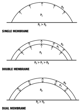
Figure 6.1 illustrates three common membrane configurations:
• Single membrane: This is the most common type of air-supported structure. The internal pressure (P1) is kept approximately 0.03 psi above the external atmospheric pressure (P0). It is this pressure difference that keeps the dome inflated.
•
Double membrane: The air space between the two membranes is used for insulation and security. If the outer skin is punctured, the inner skin will remain supported. Both single- and doublemembrane air-supported structures require the constant use of blowers to keep them inflated.
AIR-SUPPORTED FABRIC STRUCTURES
6.1
TYPICAL GROUND-MOUNTED AIR-SUPPORTED FABRIC STRUCTURE
6.2
• Dual membrane: The internal and external pressures are the same in a dual-membrane structure. Only the area between the skins is pressurized. This inflated area can be sealed, eliminating the need for constant use of blowers, although blowers are recommended to make up losses from leakage.
GROUND-MOUNTED AIR STRUCTURES
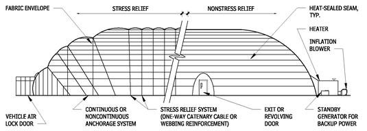
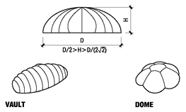
The shape of ground-mounted air structures permits the structure to meet the ground vertically, allowing gravity loads to resist the membrane tension. The semicircular cross section of the membrane structure has a curvature radius large enough to allow the fabric alone to carry wind forces that may affect the structure. If lightweight fabrics are used, catenary cables or webbing may be required for stabilization as well. Webbing is typically sewn into the fabric seams, forming a one-way system; cables are incorporated into pockets in a one-way system or formed into a cable net harness that is placed over the fabric in a two-way system.
BASIC CONFIGURATIONS OF GROUND-MOUNTED AIR-SUPPORTED FABRIC STRUCTURES
6.3
| SPAN LIMITATIONS | VAULT | DOME |
|---|
| Without cables | D = 120’ | D = 150’ |
| With cables | D = 400’ t | D = 600’ |
CONTINUOUS ANCHORAGE DETAILS
6.4
NOTES
6.2 For temporary structures, anchorage system may be water tanks, sandbags, earth screw anchors, and so on, depending on conditions. 6.4 Beam design is based on actual uplift of air structure at the design inflation pressure and wind load.
Contributor:
Paul Gossen, Geiger Engineers, PC, Suffern, New York.
LONG-SPAN DOME STRUCTURE
6.5
The membrane in a long-span dome structure must be patterned to carry loads without wrinkling. Structural behavior is nonlinear with large displacements. The roof shape must be established so that under maximum load the horizontal components of the cable forces result in minimum bending moment in the compression ring. Consult an air-supported structure specialist to integrate structural and architectural requirements.
LONG-SPAN STRUCTURE SUPPORT DETAIL
6.6
The perimeter compression ring in a long-span structure must be independent of the support structure to prevent radial restraint.
PRE - ENGINEERED STRUCTURES
METAL BUILDING SYSTEMS
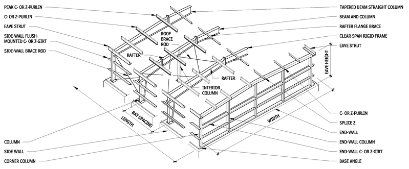
Metal building systems are available in standard framing sizes and types from various manufacturers. Commonly used terms in the metal building industry:
• Bay: The dimension along a wall between the centerlines of wall columns and the dimension from the outside of an end wall corner column to the centerline of the first adjacent wall column. Spacings range from 18 to 30 ft, with 20 to 25 ft most common.
• Width: Measured from the surface of the outside wall girts. Inside clearance varies.
• Eave height: Measured from the bottom of a wall column to the top of an eave strut. Nominal 2-ft increments vary from 10 to 30 ft.
• Diagonal bracing: Normally required in the plane of the columns and beams in one or more bays to prevent racking and to resist lateral loading perpendicular to the span of the frames.
• Girts: Horizontal structural members that transmit lateral loads (pressure and suction) from the exterior walls to the columns. Sag rods may be needed to support the girts about the weak axis and to achieve design economy.
• Anchor bolts: Necessary to resist reactions at column bases. Foundations must be designed for reactions transmitted by the column bases and anchor bolts.
Designers should verify that individual manufacturer’s standard practice and any special design considerations meet or exceed established engineering principles, local practice, and applicable building codes.
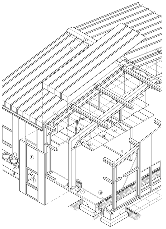
The letters enclosed in parentheses identify the respective components in Figure 6.7.
METAL BUILDING SYSTEM
6.7
STRUCTURAL COMPONENTS
Rigid steel frame (A)
Cast-in-place concrete foundation and slab (B)
ENVELOPE COMPONENTS
Roof: Standing seam metal roof (C); blanket insulation (D) Walls: Window assembly (E); insulated metal wall panels (F)
Floor: Dampproofing (G) and vapor barrier (H) MECHANICAL COMPONENTS
HVAC: Ducts and diffusers (I); heat pump (J); ridge vent (K)
INTERIOR COMPONENTS
Ceilings: Suspended acoustical tile ceiling (L)
Floors: Carpet (M)
Lighting: Fluorescent light fixtures (N) and natural light
Contributor:
Richard D. Rush, AIA, The Building Systems Integration Handbook (John Wiley & Sons, 1986).
Metal building systems are predominantly used for single-story warehouse, agricultural, and light industrial facilities, though there is increasing demand of there use for office and retail facilities, and even expansion into the multistory market. This construction approach is particularly advantageous for applications requiring large interior clear spans, the support of heavy overhead cranes, or substantial expanses of roof, the metal buildings systems industry is able to respond to highly specialized needs, while still employing standardized structural components and factory fabrication.
Metal building systems take advantage of factory assembly techniques and quality control. The structural integration of frame components with the building skin, for strength and rigidity, permits economy in the size and number of steel framing components. Primary and secondary framing members, fasteners, and panels interact to produce a light, stable building envelope. Framing and cladding components are designed, engineered, and fabricated in a plant, then shipped to the project site for erection. Often, the same company designs, engineers, and builds the system.
The metal building system integrates lightweight structural and envelope components, each of which add strength and rigidity to the overall form. The light weight of the envelope system, which is an asset for shipping, is, however, especially vulnerable to wind uplift requiring care in design. Building corners and edges are particularly subject to wind-induced uplifting and suction. Additionally, the thin sheet steel wall panels may present acoustical issues when privacy or sound isolation are an issue.
The standing seam metal roof system requires less maintenance than other alternatives, and its long-term performance record is excellent. Most standing seam metal roofs provide a free-floating monolithic membrane, connected by a series of slotted clips that allow movement. This method freely accommodates expansion /contraction cycles caused by thermal changes. In addition, a variety of details, colors, and finishes are available. The standing seam metal roof may present several areas of concern to architects: the modularity of roof panels and seams, important for locating plumbing stacks, skylights, and other roof equipment.
Although the structural and envelope systems of metal buildings are usually highly integrated, metal building system manufacturers rarely consider the mechanical and interior components in any detail.
When using a metal building system a variety of exterior cladding alternatives are available, including lightweight corrugated metal, insulated sandwich panels that provide both interior and exterior finishes, masonry, and stucco. Metal building system manufacturers also offer door, window, and skylight components as integral parts of the envelope and interior. Designating responsibility for engineering, fabrication, and construction may allow better cost control. Architects working with metal building systems can rely on technical support from the manufacturer, including the preparation of fabrication and subsystem engineering documents.
The typical rectilinear nature of metal building systems frequently results in buildings that are more easily expanded. Mechanical and interior components are integrated in the ceilings or in the structure, but the mechanical equipment is normally kept on the exterior, sometimes presenting difficulty with visual integration.
BUILDING TYPES AND WIDTHS
6.8
Contributors:
Based on Richard D. Rush, AIA, The Building Systems Integration Handbook, (John Wiley & Sons, Inc., 1986); Robert P. Burns, AIA, Burns and Burns, Architects, Iowa City, Iowa.
FRAMING SYSTEM COMPONENTS
6.9
MASONRY AND BRICK VENEER WALL SECTION
6.10
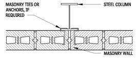
MASONRY TO COLUMN CONNECTION
6.11
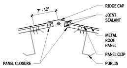
RIDGE DETAIL
6.12
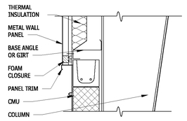
MASONRY WALL AND METAL PANEL CONNECTION
6.13
METAL WALL PANEL SECTION
6.14
NOTE
6.14 A sidewall girt may be inset between columns, attached by clip angles to the steel frame.
Contributors:
Based on Richard D. Rush, AIA, The Building Systems Integration Handbook, (John Wiley & Sons, Inc., 1986); Robert P. Burns, AIA, Burns and Burns, Architects, Iowa City, Iowa.
EXTERIOR ALUMINUM SPHERE DOMES
There are a number of manufacturers of planetarium interior projection domes that also manufacture, design, engineer, and install exterior modular dome assemblies. Components are modular and can be delivered to the site ready for assembly in conjunction with modular structural framing. Detailing is unique to each project and must be developed with the manufacturer.
The exterior skin is usually lightweight aluminum or stainless steel with a custom aluminum frame. The aluminum rib-frame consisting of hubs plates, ribs, and headers made from aluminum tubes and plates supports the exterior aluminum panels and seams. Major seam may be as wide as 1 in. and minor seams 1/4 in., when a seamless appearance is desired, the joints can narrower. The rib-frame is attached with threaded rod anchors and washers to a second spherical dome made of fire-resistance-rated, curved plywood panels attached to a curved aluminum structural tube-framing system. A sheet waterproofing and sprayed foam roofing is applied to the curved wood panels. A “zenith hub” on top of the dome connects the aluminum panel units. The aluminum exterior surface has concealed fasteners attaching the panels to the tube supports, and the connections form a watertight dome roof.
SPACE FRAME DOMES
A space frame is a three-dimensional truss with linear members that form a series of triangulated polyhedrons. It can be seen as a plane in constant depth that can sustain fairly long spans and varied configurations of shape, including dome shapes.
Space frames usually are engineered, fabricated modules, assembled on-site.
Dome roof modules can be a single-layer lattice membrane, a double layer with deep diagonals, or a double layer with vertical posts in Vierendeel truss configuration. Each manufacturer has many geometry patterns, such as geodesic, lamella, and others with unique names to the manufacturer; consult vendors for available dome structural patterns. Domes can be circular, parabolic, elliptical, compound parabolic, and inverted parabolic. Because of the inherent strength of double-curved surfaces, domes can span as far as 1000 ft. Space frame domes are made of galvanized or plated steel, stainless steel, or lightweight aluminum, and can be painted. Structural sections can be tubes, I-beams, or even angle or channel shapes. Node connections can be bolted bent plate, bolted flat gusset plate, and full sphere or partial sphere with screw-in or welded connections and cylindrical hubs.
ALUMINUM EXTERIOR SPHERE DOME
6.15
Systems are offered with glass or thermally insulated aluminum panels connected directly to the structural members, using extruded shapes and materials to receive the panels. Glass panels can have flush-glazed or batten-cap glazing connections. Numerous exterior cladding surfacing options are available, including insulated glass, metal panel decks, and thermal insulate sandwich panels.
The benefits of space frame domes are their light weight, inherent rigidity; variety of form, sizes, and spans; and compatible interaction with building mechanical infrastructure support systems.
SPACE FRAME DOMES
6.16
Contributor:
William Sarama, AIA, Skidmore, Owings & Merrill LLP, New York City, New York.
CABLE - SUPPORTED STRUCTURES
Cables and chains are structural elements unique in their load-carrying characteristics; they are capable only of resisting loads in tension, not compression or flexure. Steel is a material that is most efficient at resisting loads in tension, so very efficient structures can be formed if structural elements can be arranged such that many or all of the structural elements are in tension. The delicate, lightweight structures that can be created from cable-supported systems are a natural choice for the structural support of glazed façades and roofs, surfaces where the resulting potential for transparency is most advantageous.
LOADING AND VIBRATION PERCEPTION
Wind loads are often the controlling conditions for lightweight facade and roof systems, and are often of a similar magnitude in an inward and outward direction. Lightweight structural systems typically require a similar stiffness in both directions. For lightweight roof systems, the uplift wind load often exceeds the weight of the roof. Façade and roof systems can also accommodate more flexible supporting structures than floor framing due to the reduced ability of occupants to perceive movements through sight alone.
VERTICAL WALL SYSTEMS—CABLE TRUSSES
Cable truss systems are often used for wind bracing of tall, glass façades, and less conventionally, for the support of roof skylights. Trusses can be formed using a structural steel compression chord and a cable as the tension chord (Figure 6.17). This form of truss is lightweight and visually unobtrusive, but is capable only of resisting load in one direction. This truss type is, therefore, only appropriate for specific applications where it is known that the total load on the surface will be applied from only one direction.
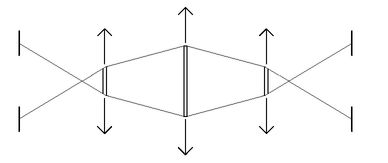
When two of the trusses described above are connected back-to-back, to form a lightweight truss assembly it can support loads in both directions as shown in Figure 6.18. The figure shows a configuration with two compression chords forming a frame containing the two curved cables. An alternate but structurally similar configuration can be achieved with two curved cables outboard of a single compression chord. If the support points are immovable, the compression chords can be eliminated and the cable truss can support loads by each chord acting as hanging cable (Figure 6.54), similar to the main cable of a suspension bridge.
CABLE TRUSSES
6.17
LIGHTWEIGHT TRUSS SYSTEM
6.18
CABLE TRUSS SUPPORTING LOADS BY EACH CHORD
6.19
The cable-truss-supported glass walls at the Tokyo International Forum, designed by Rafael Viñoly are dramatic examples of the transparent walls that can result from the use of this type of cable support assembly.
CABLE SUPPORTED VERTICAL WALL ASSEMBLIES
When arranged in a rectilinear grid and tensioned to approximately one-quarter to one-third of their breaking strengths, a planar “cable-net” has significant resistance to being deformed out of plane. This characteristic makes for an ideal structural solution for highly transparent glass walls.
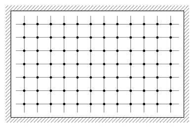
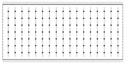
Cable-nets can be arranged as two-way systems consisting of horizontal and vertical systems (Figure 6.20) or as one-way systems consisting only of vertical cables (Figure 6.21). Two-way systems allow for longer spans to be constructed (100 by 100 ft can be achieved; larger spans are possible, but may require specialized solutions). Two-way systems also allow for simple detailing at boundary conditions, as the deflection of the cable-net is always zero at the perimeter. One-way systems are efficient for relatively short (less that 50 ft), wide walls, where the addition of horizontal cables does not add significantly to the stiffness of the wall.
Rectangular glass panels approximately 5 by 5 ft are attached to the cable-net, typically by being clamped at the glass corners by node castings, which also connect to the cable intersections (Figure 6.22). The only visible structural elements are the cables that align with the joints between the glass panels. The assembly is flexible, with maximum deflections in a 50-year return period wind event typically limited to L/45 to L/50, where L is this shortest span of the cable-net wall. The node castings are typically detailed in a manner that allows some rotation of the glass at the clamp point, allowing the cable-net to deform without breaking the glass panels. The vertical cables are typically located close to the glass, to minimize eccentric gravity loading on the cables, which otherwise causes each course of glass panels to lean outward from the vertical plane. Joints are typically sealed to maintain weatherproofing.
HORIZONTAL AND VERTICAL CABLE-NET
6.20
ONE-WAY CABLE-NET WITH VERTICAL CABLES
6.21
The most notable early application of this system is the 70-ft-tall, 150-ft-wide cable-net wall at the Kempinski Hotel in Munich, Germany, completed in 1993 More recently, a significant development in the achievable size of cable-net walls is the 300-ft-tall, 200-ft-wide cable-net wall at the New Beijing Poly Plaza in Beijing, China, completed in 2005.
NODE CASTINGS USED TO CLAMP CABLE-NET
6.22
CABLE SUPPORTED ROOF ASSEMBLIES
Cable-supported roof assemblies have been utilized in a variety of configurations and scales, varying from the enclosure of courtyards to the roof assembly of sport stadiums. Roof assemblies supported by cable trusses are often utilized using a conventional beam-and-joist concept, but with heavier structural steel beams or trusses being replaced with cable trusses.
Cable-nets can also be used to support roof assemblies, although a planar cable-net is generally not the used. A planar cable-net will sag under the weight of the roof glazing; and when in this permanent deformed position, it has very little resistance to upward movement due to wind uplift. A cable-net can be stiffened for use as a roof assembly by deforming the net into a hyperbolic paraboloid or saddle shape. In this configuration, the cables in one direction curve upward, and in the other downward, therefore providing stiffness in both directions.
Additional structural systems employed in stadium roofs include tension or inverted domes (where the cladding may form a convex dome, but the structure is effectively a concave dome of cable elements in tension), and suspended roofs hung from support points on pylons above the roof level. All roof forms possible using fabric roofs can also be formed with a mesh of cables replacing the structural fabric, then clad with fabric, wood, or other materials.
CABLE MATERIALS
The cables are typically architecturally exposed and difficult to apply coatings to, therefore cable elements are generally manufactured from corrosion-resistive materials. Stainless steel cables are the most common material used in cable-supported structures, though galvanized steel cables can also be used. Stainless steel cables from 1/8 to 1-1/2 in. in diameter are commonly available, and galvanized steel cables can be manufactured in diameters exceeding 6 in. Stainless steel cables are typically connected to other elements through swaged end fittings, a technology that allows for relatively small end fittings (fitting diameter is approximately twice the cable diameter) but that is difficult to employ on cables larger than 1-1/2 in. diameter. Larger-diameter galvanized cables are typically connected to other elements using zinc-poured end fittings.
CABLE FIREPROOFING
It is possible but difficult to fireproof cable elements. Cable-supported structures are generally most suitable for use in conditions where fireproofing of the cables is not required by code or can be shown to be unnecessary through the use of engineering analysis. Typically, the principal attraction of the use of cables in structures, being the minimal dimensions of structural elements, is lost when cables are required to be fireproofed.
ENGINEERING
Due to the unconventional nature of these structural systems, an engineer familiar with the design of cable structures or a specialty manufacturer is typically consulted when designing cable-supported façade and roof assemblies of this type.
INSTALLATION
The construction tolerances required, both in terms of geometrical tolerances and tolerances on the installed cable tensions required in the final configuration, make it important that the installation of cable-supported façade and roof assemblies are performed by a qualified installer contractor.
FABRIC STRUCTURES
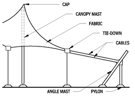
There are two types of nonpneumatic fabric structures. One supports the fabric membrane with a rigid frame, usually constructed of metal, the other is a self-supporting fabric membrane kept in tension with a supporting structure of steel or concrete. The rigid frame structures typically form pyramidal or long, continuous geometric shapes like sheds or barrel vaults. The self-supporting structures rely on opposing curves to distribute the necessary tension and typically form saddle, conical, or hyperboloid (anticlastic) shapes.
The structure that creates and maintains tension on the fabric can consist of cables and masts, a compression ring, trussed gridwork, or tied edges. These mechanisms create tension in the fabric sufficient to keep it taut. Any compressive loads imposed on the fabric will be balanced or, at most, reduced by the prestress created by the structure.
FABRIC STRUCTURE MATERIALS
The intended life span of the structure is an important factor in design decisions, fabrication details, and the cost of architectural fabric structures. The life span is most affected by the fabric material or membrane selected. Fabric is a directional material and does not have the same strength or elongation in all directions under a load. Materials with little creep are preferable for tensioned structures, as original prestress can be lost if the fabric stretches or deforms. Details allowing for retensioning must be incorporated if materials with moderate to high creep are used. Generally, the materials used in a membrane are composites consisting of a woven substrate protected with an applied coating.
The membrane is the principal structural component of a self-supporting or tensioned fabric structure. Two materials are generally used for membranes: polyvinyl chloride (PVC)-coated materials and fluorocarbon- (Teflon-) coated glass fiber fabric.
• PVC-coated polyester is a composite material composed of vinyl coating over both faces of a woven polyester fabric. The material is inexpensive, strong, translucent, and easy to fabricate, but has a limited life span and is only fire-resistant. For these reasons, it is used only in temporary or semipermanent structures.
• Fluorocarbon-coated glass fiber fabric is classified as a noncombustible material. Besides its advantages in fire safety, this fabric is extremely long-lasting, self-cleaning, and translucent, and is the accepted material for most permanent installations.
Development continues in fabric technology, and new products such as silicon-coated glass fiber may offer an improvement in the range of material characteristics.
FABRIC STRUCTURE DESIGN
In recent years, the structural design of fabric structures has improved due to the increased use of the computer in the engineering process. The first step in the design process aided by computer modeling is the definition of an acceptable surface geometry, such as the hyperboloid. A membrane mesh or network is then developed, representing the surface as a grid of lines. This graphic model is “prestressed,” and the reactions are analyzed in an iterative, or repetition-based, process. Live loads such as wind, rain, or snow are applied to the model, and the stresses calculated n order to select the fabric and design the supporting structure or foundation.
The design, fabrication, and construction of fabric structures require close coordination among the architect, engineer, fabricator, and installer throughout the process, to ensure the strict quality control this technology requires. However, because most of the work is completed in the factory, minimizing on-site construction time, it is not unreasonable to maintain tight specifications.
FABRIC STRUCTURE DESIGNS
6.23
TYPICAL CONE-SHAPED TENSILE FABRIC STRUCTURE
6.24
Contributor:
Aaron Mazeika PE, Skidmore, Owings & Merrill LLP, San Francisco, California; Industrial Fabrics Association, Roseville, Minnesota; Adapted with permission from Architectural Fabric Structures: The Use of Tension Fabric Structures by Federal Agencies (Washington National Academy Press, 1985); Kathleen O’Meara, OM Architecture, Baltimore, Maryland; David Campbell, Geiger Engineers, Suffern, New York.
FABRIC STRUCTURE ANCHORAGE DETAILS
6.25
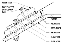
FABRIC EDGE CLAMP—ATTACHMENT DETAIL
6.26
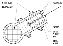
EDGE OR CATENARY CABLE—ATTACHMENT DETAIL
6.27
The two primary ways of attaching fabric to anchorages are with edge catenary cables or clamps. Catenaries allow free-form design. When a tighter connection between fabric and building structure is required (e.g., on roofs, skylights, and air structures), a clamp system is used, in which the fabric is sandwiched between clamping bars or plates, which are bolted to the structure. Some membrane structures use both kinds of attachment. Air structures sometimes have sleeves and cables, plus a fabric closure panel that extends beyond the cable.
Tensile structures usually are custom-designed; anchoring and connection details also are customized. However, basics, such as clamping systems, have become more standardized. Some frame and connection materials have been adapted from other industries, such as space frames and marine rigging. To determine the appropriate design aesthetic for a project, consider the following aspects:
• Tensile structures are flexible, and the details must be designed to move under loads.
• Tensile structures weigh a fraction of the amount of other buildings, and many of the materials are translucent.
• Lateral forces play a much greater role in tensile structures than in conventional structures.
• It is essential that the physical resolution of each element’s force vector (the angle of direction and magnitude) be accurate.
• Details, material specifications, and reaction forces affecting interfacing structures should be developed with an engineer or fabricator with the expertise in the design of fabric structures.
LOG STRUCTURES
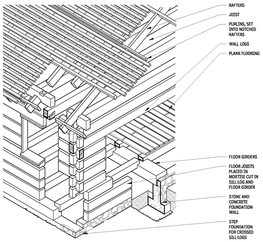
Residential log buildings have become a significant part of the home construction industry. The log house industry comprises two main segments: kit build, which are manufactured, or milled, and custom-built log houses.
• Houses built from kits use logs that have been machined or milled to a uniform shape in a variety of profiles. Although kitbuilt houses can be put together quickly and with few construction skills, the finished product tends to look artificial.
• Custom-built log houses are produced from hand-peeled, handnotched logs in their natural profile. These structures more closely resemble a traditional log construction. Kits for handhewn houses are also available, but their reconstruction on-site is often complicated because of longer log lengths and the heavier weight of the logs. A hydraulic crane is usually required. Many building officials require a structural engineer’s approval to accompany the plans, whether the log house an architect hired by the owner generates the construction documents
DESIGN CONSIDERATIONS
A number of design issues are important to consider when building log structures:
• Hewing logs into square members removes most of the sapwood, which reduces the weight of the log and its susceptibility to insect damage and rot. The flat surfaces of square logs are also easy to work with.
• Damage from rot (fungal decay) can be prevented or controlled in three ways: remove sapwood, which is high in cellulose and lignum on which fungi feed; reduce the log’s moisture content to 20 percent or less by air or kiln dying; or provide proper air circulation under floors and around foundations. Generous roof overhangs and properly maintained gutters help keep water off the sides of the building.
• Insect damage from termites, beetles, and carpenter ants can be prevented by properly seasoning the wood (kiln or air drying) and by providing continuous vapor retarders at grade. Also, good air circulation can help prevent infestations.
• Exposed interior logs must be coordinated carefully with placement of plumbing, electrical wiring, and mechanical equipment.
• Good drainage around the building is important, as log buildings are susceptible to rot.
• Manufacturers of fabricated log structures offer milled log details to reduce air leakage and improve weatherability of the wall. Such details include tongue-and-groove joints, dovetailing, use of steep splines, and butyl gaskets.
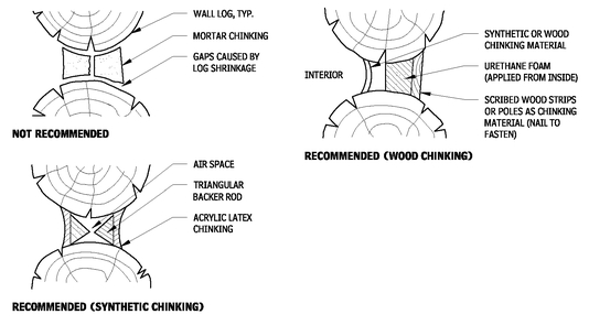
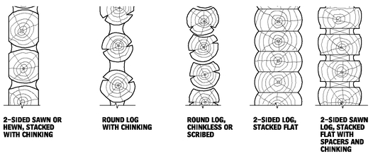
• Spaces between individual logs (chink area) are filled with chinking, which can vary in width.
Contributor:
David Campbell, Geiger Engineers, Suffern, New York.
LOG FRAMING
6.28
CHINKING DETAILS
6.29
WOOD PRESERVATION—DETAIL
6.30
SCRIBED OR CHINKLESS LOG JOINERY
6.31
Contributor:
Arthur Theide, Log Homes Connect, Hailey, Idaho.
TYPICAL LOG WALL PROFILES
6.32
TYPICAL CORNERS
6.33
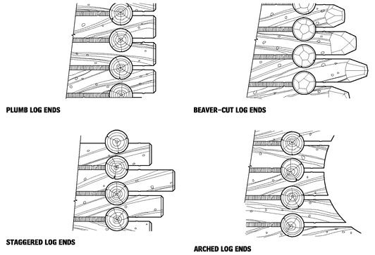
LOG END PROFILES
6.34
Contributor:
Arthur Theide, Log Homes Connect, Hailey, Idaho.
